
Enabling Data Flows in UML Interactions
Marc-Florian Wendland, Ramon Barakat and Martin Schneider
Fraunhofer Institut FOKUS, Kasierin-Augusta-Allee 31, 10589 Berlin, Germany
Keywords: UML Interactions, Data Flow, Object Flow, Data Sink, Data Source, UML Sequence Diagram, Message
Arguments.
Abstract: UML Interactions represent one of the three UML behaviors. They describe the interwork of parts of a system
based on message exchange. UML Interactions can reside on any level of abstraction and they seem
sufficiently elaborated for high-level specifications used for sketching the communication among parts of a
system. The UML Interactions metamodel, however, reveals some deficiencies for precise specifications of
data values and data flows. Even UML 2.5 still does not provide concepts for data flows in UML Interactions.
In this paper, we suggest a profile-based extension that integrates data flow concepts with UML Interactions.
The extension supports accessing (usage of) values located in data sources and assignment (definition) of
values to data sinks in the context of message exchange and invocation of Interactions. The proposed
extension improves the expressiveness of UML Interactions in a minimal invasive manner and makes it
similar to the capabilities of UML Activities regarding the specification of data flows.
1 INTRODUCTION
The UML Interactions metamodel is agnostic of
concepts to describe data flows. This fact is already
known and was way back submitted as issue, when
UML 2.0 was finalized (see the issues in the OMG
issue #8761 and #8786 in the OMG UML database
http://www.omg.org/issues/uml2-rtf.open.html). In
short, data flow enables accessing values from data
sources (usage) and assigning values (definition) to
data sinks. As a modeling language that follows
object-oriented paradigm in the first place, UML
(UML, 2015) supports data flow concepts in the
realm of UML Activities by means of ObjectFlow and
ObjectNode and dedicated Actions to manage usage
and definition of data values from data sources and
data sinks. Wendland et al., (2013) have already
highlighted that UML Interactions and UML
Activities are not sufficiently harmonized with each
other. As a matter of fact UML Interactions is lacking
an important concept of modern
programming/modeling language and paradigms: the
ability to use values located in data sources as
arguments of Message as well as the assignment of
values contained in Message arguments to data sinks
accessible by the receiving part.
The genuine motivation for this work stems from
both the model simulation and model-based testing
domain. In both domains data flow concepts are
highly required. Although UML Activities and
Interactions seem adequately integrated with each
other in order to describe data flows in UML
Interactions, it is not the case (see Wendland et al.,
2013). Of course, the UML provides the ability to
specify methods for BehavioralFeatures that could
deal with data flows eventually. However, in our
experiences (in particular in model simulation and
testing) the so called fragmented method design
pattern (name is recommended by Bran Selic) is often
applied. The fragmented method pattern is based on
the idea that the reaction to a BehavioralFeature
invocation is not handled in its respective method, but
rather by the behaviour where the invocation is
described (e.g. the UML Interactions). Instead of
foreseeing the semantics of a BehavioralFeature from
the very beginning, the semantics is fragmented into
pieces, each describing a certain reaction of the callee
at a certain point in time. The fragmented method
pattern in in particular applied on higher level of
abstraction including testing and model simulation. A
more fundamental motivation of our work is that we
believe that engineers should be able to select their
appropriate UML behavior kind. For example, if an
engineer decides to describe the method of a
BehavioralFeature as UML Interaction (as opposed to
UML Activity), he/she ends up having the same
250
Wendland, M-F., Barakat, R. and Schneider, M.
Enabling Data Flows in UML Interactions.
DOI: 10.5220/0005689002500257
In Proceedings of the 4th International Conference on Model-Driven Engineering and Software Development (MODELSWARD 2016), pages 250-257
ISBN: 978-989-758-168-7
Copyright
c
2016 by SCITEPRESS – Science and Technology Publications, Lda. All rights reserved

problems regarding data flows as mentioned before.
Therefore, it is required to incorporate the notation of
data flows directly into UML Interactions.
The scientific contributions of this paper are:
Raising awareness of UML Interactions
deficiencies for expressing data flows
Identification of data sources and data sinks in
UML Interactions
Specification of a UML profile to enable data
flows in UML Interactions
The remainder of this paper is structured as follows:
In Section 2 the work related to our work will be
summarized. Section 3 discusses the deficiencies of
the UML Interactions metamodel with respect to
precise data handling and data flow. In section 4 a
possible solution is analysed. Section 5 elaborates the
Interactions Data flow extension. This profile is
finally applied to a concise case study in section 6.
Section 7 eventually concludes this paper and
sketches potential future work.
2 RELATED WORK
Haugen compares UML Interactions and Message
Sequence Charts (Haugen, 2004) showing that
Interactions and MSCs are similar down to small
details. Haugen, Stolen, Husa, and Runde have
written a series of paper on the compositional
development of UML Interactions supporting the
specification of mandatory and potential behavior,
called STAIRS approach (Haugen and Stølen, 2003;
Haugen et al., 2005). Although the compositional
idea is reflected throughout the series, a special
interest is dedicated to a fine-grained differentiation
of event reception, consumption and timing (Haugen
et al., 2005) and the refinement of Interactions with
regard to underspecification and nondeterminism
(Runde et al., 2005; Lund and Stølen, 2003).
Formal semantics of UML Interactions and
sequence diagrams were several times discussed.
Störrle presented a formal specification of UML
Interactions and a comparison of UML 2.0 and UML
1.4 Interactions (Störrle, 2003; Störrle, 2004). A
similar work was done by Knapp and Cengarle
(Knapp, 1999; Cengarle and Knapp, 2004), Li and
Ruan (Li and Ruan, 2011) and Shen et al., (2008).
Special attention was set to the semantics of assert
and negative CombinedFragments (Störrle, 2003;
Harel and Maoz, 2006), though.
Model checking on formal semantics of
Interactions was done by Knapp and Wuttke (Knapp
and Wutke, 2006).
Wendland et al., (2013) focused the precise
definition of Message arguments of UML
Interactions. Their work is different to the previously
mentioned papers that mostly dedicated to the trace
semantics of Message reception and consumption
within UML Interaction. The work described in this
paper continues parts of the work of Wendland,
Haugen, and Schneider, but concentrates solely on the
integration of data flows concepts into the UML
Interactions metamodel as a UML profile.
3 PROBLEM STATEMENT
In this section, we emphasize the deficiencies of the
UML Interactions metamodel with respect to express
data flows. Therefore, we firstly discuss the relevant
metamodel and semantics of UML Interactions
required to understand both the problem statement
and the solution. Afterwards, we identify the
deficiencies of the UML Interactions metamodel
regarding the data flow concepts in the context of
UML Interactions.
The terms data sinks and data sources always
refer to instances of the UML metaclass
ConnectableElement since it constitute the lowest
common denominator of Property and Parameter,
and, as such, the sinks and sources for accessing or
assigning values used in or obtained from message
exchange. Table 1 summarizes the data flow
scenarios we considered relevant when working with
data and invocations in a more precise way. Our work
addresses each scenario. Moreover, the table
identifies which UML metaclass assumes which role
(data source or data sink) per scenario.
3.1 Relevant Foundations of UML
Interactions
UML Interactions describe the communication
between (potentially loosely coupled) parts of a
system. The most important building blocks of UML
Interactions are Messages that constitute information
exchange between different parts, and Lifelines that
represent those communicating parts. A condensed
view on the UML Interactions metamodel sufficient
to comprehend our work is shown in Figure 1. A
Message represents either the invocation of an
Operation or the sending and reception of a Signal.
The first kind represents either an asynchronous
or synchronous call, or a reply in case of a preceding
synchronous call. The second kind (i.e., the sending
of a Signal) is by definition always asynchronous.
UML classifies Messages either as request Messages
Enabling Data Flows in UML Interactions
251
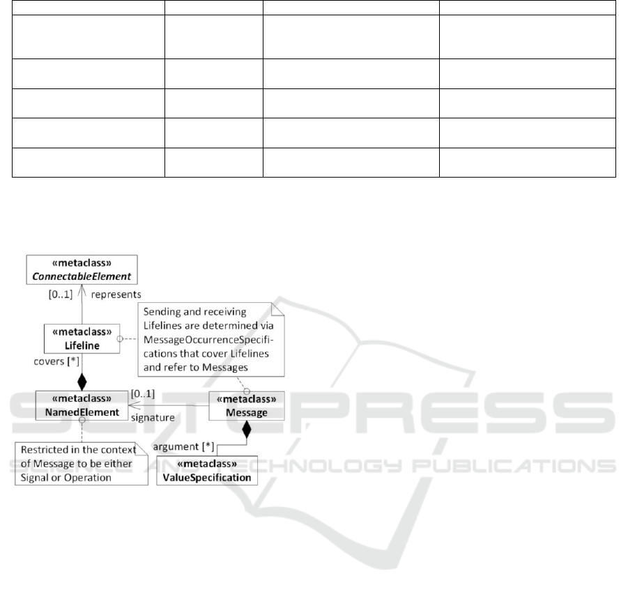
Table 1: Data flow scenarios for UML Interactions.
Scenario Context Data source Data sink
Using data sources as
actual parameters of an
invocation
request Message
ConnectableElements
accessible by sending Lifeline
in-kind signature elements
(Parameter or Property)
Assigning actual
parameters to data sinks
request Message
in-kind signature elements
(Parameter or Property)
ConnectableElements
accessible by receiving Lifeline
Using data sinks as return
values
reply Message
ConnectableElements
accessible by sending Lifeline
out-kind signature elements
(Parameter or Property)
Assigning return values to
to data sinks
reply Message
out-kind signature elements
(Parameter or Property)
ConnectableElements
accessible by sending Lifeline
Direct flow of value among
messages
Request/reply
Message
Signature elements of a
previous Message
Signature elements of the
context Message
(i.e., in terms of OCL Message.messageSort <>
MessageSort::reply
) or reply Messages (i.e.,
Message.messageSort=MessageSort::reply).
Figure 1: Parts of the UML Interactions metamodel.
Messages commonly convey data in terms of its
arguments to the receiver. The arguments of a
Message have to correspond to the
ConnectableElements determined by its signature
which manifest either in an instance of the metaclass
Parameter (in case of an Operation signature), or
Property (in case of a Signal signature). We
henceforth call the constituent of a Message’s
signature signature element (which always refers to
an instance of ConnectableElement as superclass of
both Parameter and Property). A signature element
has always a direction, represented by the UML
metaclass enumeration ParameterDirectionKind that
indicates whether the corresponding argument is
passed into, out of, or both, into and out of the
invoked Message signature. These directions have the
following semantics:
- in: Parameter values are provided by the caller
- inout: Parameter values are passed in by the
caller and (possibly) different values are passed out to
the caller
- out: Parameter values are returned to the caller
- return: Parameter values are passed as return
values back to the caller.
For the sake of simplicity, we henceforth use the term
in-kind parameters to summarize signature elements
with direction in and inout, and out-kind parameters
to summarize signature elements with direction out,
inout and return. Signature elements for Signal
sending (i.e., the Properties of the Signal that is send)
always have the direction in, even though they are not
Parameters. Message arguments refer to instances of
the metaclass ValueSpecifications. As defined by
UML, a “ValueSpecification is the specification of a
(possibly empty) set of values.”
3.2 Deficiency 1: Access to Data
Sources (Usage)
The UML specification (see clause 17.12, sub-clause
Message, sub-sub-clause Constraints, bullet point
arguments in UML 2.5) constrains the possible
arguments for Message to: “i) attributes of the
sending lifeline, ii) constants, iii) symbolic values
(which are wildcard values representing any legal
value), iv) explicit parameters of the enclosing
Interaction, v) attributes of the class owning the
Interaction.”
As said before, arguments of Messages have to be
instances of ValueSpecifications. As such are not
capable of referring ConnectableElements per se,
neither Properties nor Parameters can be utilized as
data sources for arguments of Messages. This
deficiency, however, is not new or unknown. Right
from the beginning of the UML 2.0 finalization work,
two issues have been submitted to the official OMG
UML issue list that highlight exactly this flaw (see
#8786 in the UML issue database). As the submitter
of the issue correctly indicated, ValueSpecification is
MODELSWARD 2016 - 4th International Conference on Model-Driven Engineering and Software Development
252

not able to access ConnectableElements.
3.3 Deficiency 2: Assignment to Data
Sinks (Definition)
Assignment of parameters or attributes of an invoked
Operation or received Signal to accessible data sinks
of the receiving context is again a major concept to
describe data flows. At least, the UML specification
specifies a textual concrete syntax for expressing
assignment of out-kind parameters in the context of
reply Messages (see clause 17.4.4). This concrete
syntax, however, has no effective counterpart in the
UML Interactions metamodel and no definition, how
the assignment target manifests in models. There is
no mapping from the concrete to abstract syntax, thus,
it is not clear how assignments shall be expressed by
means of UML metaclasses.
This deficiency was also reported at beginning of
the UML 2.0 finalization work (see issue #8899 in the
UML issue database). As a side note, the UML
specification merely speaks about the assignment of
out-kind parameters in the context of reply Messages.
UML does not even consider the assignment of in-
kind parameters of request Messages (Operation calls
or Signal sending) to accessible data sinks of the
invoked Lifeline. This, in turn, means that the
invoked Lifeline does not have the ability to store
received data for later use at all.
4 SOLUTION ANALYSIS
The before mentioned two deficiencies lead to a
situation where UML Interactions are not applicable
for precise and convenient specifications of data
exchange using Messages based on UML
Interactions. The main challenge in improving the
UML metamodel officially (i.e., as part of the UML
standardization working group at OMG) is to keep
backward compatibility, which makes it hard to really
evolve the metamodel. This is also the reason, why
the improvement suggestions of Wendland, Haugen
and Schneider have not been incorporated.
A feasible solution would be the definition of a
dedicated UML profile that introduces the required
concepts as a non-invasive extension to the UML
Interactions metamodel. This would be similar to the
normative but optional UML standard profile.
We deliberately spared data modifications,
because the UML Action semantics is capable of
doing that. The proposed extension solely mitigates
the necessity to let values flow among
ConnectableElements, Message and Lifelines. Once a
Message argument is assigned to an
ConnectableElement UML Actions can be utilized to
modify those values.
5 SPECIFICATION OF THE UML
INTERACTIONS DATA FLOW
EXTENSION
Following a general recommendation for developing
UML profiles (Selic, 2007), the implementation of
the UML Interactions Data Flow extension was based
on a conceptual, i.e., standalone, MOF model before
integrated into UML. This MOF model was already
presented in previous work (Wendland et al., 2013),
so we spare it in this paper. From a technical point of
view, the UML Interactions Data Flow extension is
realized as hybrid profile. The term hybrid profile is
not an established term to the best of our knowledge.
We define it as follows: A hybrid profile is a profile-
based extension of the UML metamodel that
integrates stereotypes with MOF metaclasses. It
represents a UML standard-compliant combination of
Stereotypes and MOF classes (henceforth called
profile classes) in order to technically simplify
expressive UML profiles. Every UML standard-
compliant tool is able to process these hybrid profiles.
For further information on that technical feature of
UML, see UML 2.5, clause 12.3, Profiles.
5.1 Integration with the UML
Interactions Metamodel
Figure 2 depicts the Stereotypes of the Interactions
Data Flow extension that are responsible for the
integration. The abstract stereotype IDFConstituent is
responsible to describe the flow of data between data
sinks and data sources. It contains an ordered set of
AssignmentSpecifications (see section 5.2). The
Stereotype ArgumentAssignmentSpecification copes
with the assignment of Message arguments to data
sinks. Besides Message, the metamodel shows also
the metaclass InteractionUse, which is spared in this
work. It resembles the handling of Messages, though.
The access to data sources defined by the abstract
Stereotype ReferencedValueSpecification. A
ReferencedValueSpecification refers to data sources
for their usage as Message (or InteractionUse)
arguments. The metaclass Expression is a subclass of
ValueSpecification. Whenever a data source shall be
used as input for an argument, it is necessary to create
an Expression as argument for the corresponding
signature element and to apply one of the concretes
Enabling Data Flows in UML Interactions
253

subclasses of ReferencedElementExpression:
- ReferencedConnectableElement: enables the
access to ConnectableElements (Property or
Parameter).
- ReferencedMessageArgument: allows reusing
arguments of a previously exchanged Message
from a later context Message. The previously
exchanged Message is identified by the
association argumentSource.
- ReferencedInteractionUseArgument: similar to
ReferencedMessageArgument.
To sum up, the abstract Stereotype IDFConstituent
either represents the assignment of an argument to a
data source (by the concrete Stereotype
ArgumentAssignmentSpecification) or the usage of
data sources as Message arguments (by the concrete
Stereotype ReferencedValueSpecification). Both
assignment and usage is based on the specification
ArgumentAssignment profile class.
Figure 2: Foundations of the extension.
5.2 Specification of Assignments
After the integration with the UML metamodel was
described, the precise specification of data sources
and data sinks in a data flow needs closer
examination. In general, an assignment is usually
decomposed into a left-hand side (data sink) and a
sequence of right-hand sides (data source). In this
article we use the symbol
’:=’ as concrete syntax for
the profile class AssignmentSpecification. Thus, an
instance of AssignmentSpecification can textually be
abbreviated as
leftHandSide := rightHandSide (,
rightHandSide)*
. The left-hand side of an
assignment is usually fix, that means, it represents an
unchangeable reference to the data sink. The right-
hand side, in contrast, can be decomposed into further
expressions, however, it is a common best practice
that right-hand side expressions are side-effect free.
This best practice holds also true for the Interactions
Data Flow extension. The notation of left-hand side
and right-hand side is also reflected in the Interactions
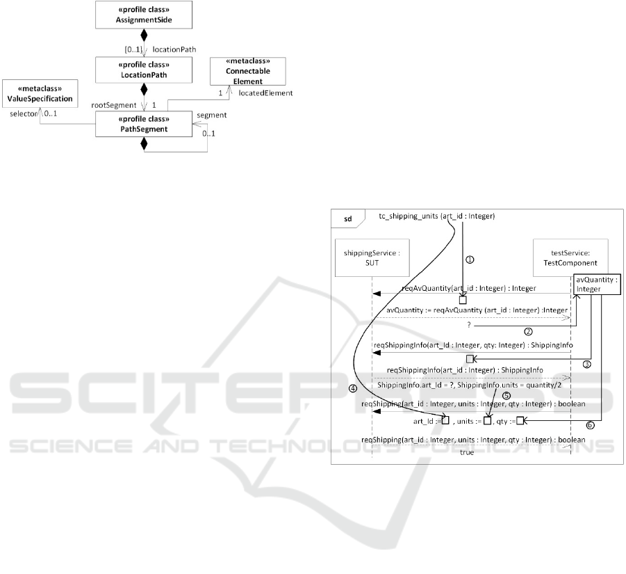
Data Flow metamodel as shown in Figure 3. The
profile class AssignmentSide allows defining either
side of an AssignmentSpecification. Both sides refer
to ConnectableElements to determine the data sink
and the data source. The respective allowed
ConnectableElement for either side depends on the
scenario in which they are participating (see Table 1).
In the context of an
ArgumentAssignmentSpecification, the right-hand
side always has to refer to a signature element of the
Message on which the stereotype is applied. The left-
hand sidehas to be an accessible ConnectableElement
of the receiving Lifeline. Type compatibility between
the Type of a right-hand side and left-hand side
ConnectableElement is required. That means that a
Type of a right-hand side ConnectableElement shall
be the same or a subtype of the Type of the left-hand
side ConnectableElement.
Figure 3: Specification of assignment sides.
5.3 Navigation and Selection
If all the values of a right-hand side shall be entirely
assigned to the left-hand side, the given metamodel is
sufficient. If, however, further refinement is required
to either navigate any of both sides by navigating
complex data types or selecting a subset of right-hand
side collections, the extension does not suffice. As
such scenarios occur often, we need additional
capability in the metamodel. These capabilities are
shown in Figure 4.
Navigation refers to the fundamental capability to
locate either of the side’s ConnectableElement by
traversing associations among complex types.
Complex nested and associated types are rather usual
MODELSWARD 2016 - 4th International Conference on Model-Driven Engineering and Software Development
254
in real scenarios, so it is required to provide a facility
to express such location expressions.
Figure 4: Navigation and selection capabilities.
Selection (in our case) refers to the ability to select
a subset of values for either side’s
ConnectableElement, if the ConnectableElement
represents a collections (i.e., a Parameter or Property
with upper bound ≥ 1). In particular if the left-hand
side multiplicity is lower than the right-hand side, it
is required to define the data subset of the right-hand
side that shall flow into the left-hand side.
In order to navigate along nested complex types,
the profile class LocationPath was integrated with
AssignmentSide. Since locating expression are solely
used for complex types, the metaproperty
AssignmentSide.locationPath has an optional
multiplicity. Each LocationPath refers to exactly one
PathSegment as its rootSegment, indicating the
starting point of the navigation expression (similar to
self in OCL (OCL, 2015)). A PathSegment refers to a
ConnectableElement and is able to recursively
contain other PathSegments. This enables a sequence
of chained PathSegment objects that navigate through
a complex object network. Let as again use a simple
textual example for better comprehension. We
assume the following specification of an assignment:
lifeline.prop1 := msg1.param2.prop2.prop3
Let us assume that the Type of the Parameter
param2 is a complex type that owns a Property prop2.
The Type of prop2 is again a complex type that owns
a Property prop3, which eventually is assignment
compatible with lifeline.prop1.
6 EVALUATION
In order to evaluate the applicability of the UML
Interactions Data Flow extension, one of the case
studies of the EU MIDAS project is taken. The
example in Figure 5 represents a functional test case
from the Supply Chain Management case study where
the proper calculation of shipping units for a given
article is verified. It is, in fact, a condensed
representation of the genuine test case due to page
restriction, shrunk down to demonstrate the data flow
capabilities of the work proposed.
The graphical notation (which is not standard
UML) has the following semantics: Similar to data
flow diagrams, arrows indicate flow of values from a
data source into a data sink. Data sinks are visualized
as black hollow rectangle. Arguments of Messages
are shown underneath their corresponding Message.
The different data flow examples are labelled with a
number. The rectangle that overlaps the Lifeline
testService:TestComponent represents a local
attribute of the Type, the Lifeline is an instance of
(i.e., TestComponent).
Figure 5: Evaluation example.
The semantics of both usage of data sources as
Message arguments and assignment of Message
arguments to data sinks were described in section 5.1.
For a better evaluation of the underlying model we
utilize UML object diagrams. For simplicity, we treat
instances of Stereotypes similar to instances of
metaclasses of the UML metamodel (which they are
not). However, the technical details of the UML
profile mechanism are no added value in the context
of the examples, and are, thus, omitted. The data
flows 1, 3, 4 and 6 do all represent a flow from a
ConnectableElement into a sending Message’s
argument. Thus, we visualize only the object diagram
for data flow 1. Since Parameters and Properties are
treated similar in our solution (by using their common
abstract superclass ConnectableElement), the object
diagrams would not vary very much, though.
Data flow 1 describes the access of Lifeline
testService to the Parameter art_id of the surrounding
Interaction tc_shipping_units. It is, thus, a
Enabling Data Flows in UML Interactions
255
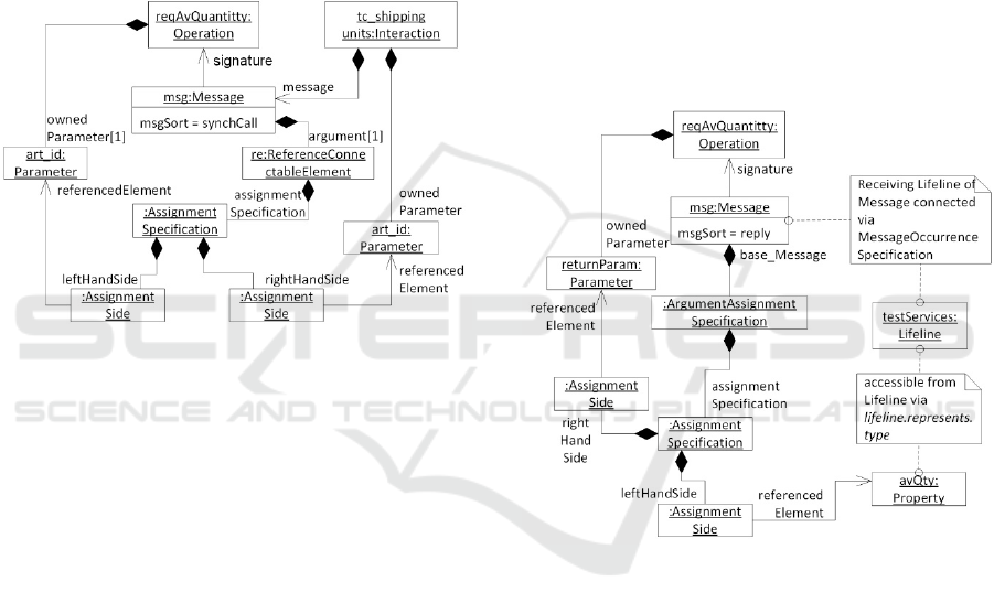
ConnectableElement accessible by the sending
Lifeline. Technically, the access is achieved with an
instance of ReferencedConncetableElement, whose
right-hand side ConnectableElement refers to the
Parameter art_id. The left-hand side of the
assignment is determined by the corresponding
context Message’s signature element of the
ReferencedConnectableElement. Correspondence is
defined by the UML 2.5 specification as index-based
relation among the argument (see link
msg.argument[1]) and the signature element (see link
reqAvQuantity.ownedParameter[1]). In the pseudo-
code notation, the object diagram would read
msg.art_id := tc_shipping_units.art_id
Figure 6: Object diagram of data usage flow.
Data flow 2 describes the assignment of a
Message argument (i.e., the symbolic value ? which
represents the wildcard any value in UTP) by the
services received by a Lifeline to an accessible
ConnectableElement of the one. The semantics of
data flow 2 together with 3 is that we store the actual
value of ? at runtime locally and use the value later
on for sending another message. In this example, the
ConnectableElement represents a Property of the
Type the Lifeline represents an instance of (i.e.,
self.represents.type.ownedAttribute in OCL).
This is depicted by the object diagram in Figure 7.
The right-hand side ConnectableElement refers to the
Parameter of the Message that serves as the base
metaclass for the Stereotype
ArgumentAssignmentSpecification. The left-hand
side, in turn, refers to the Property avQty accessible
by the Lifeline testService. In the pseudo-code
notation, the object diagram of Figure 7 would read
testService.avQty := msg.returnParameter
Since ShippingInfo is a complex type out of which
only the data located in the Property unit shall be used
as argument of request Message reqShipping, it is
necessary to utilize the navigation capabilities of the
Interactions Data Flow extension as described in
section 5.3. Therefore, the right-hand side of the
assignment (see instance of AssignmentSide in
Figure 8) contains a LocationPath whose root
segment refers to the return Parameter of the
reqShippingInfo invoked by Message
reqShippingInfo (see Figure 8). The root
PathSegment contains another PathSegment that
locates a Property of the Type (i.e., ShippingInfo) of
the return Parameter.
Even though the navigation path is rather short in
our example, it effectively demonstrates how to
establish more complex navigation paths by simply
concatenatimg PathSegments. The chain of
PathSegments can be of arbitrary length, similar to
the arbitrary length of object networks, as long as the
type of the located element of a PathSegment is not a
PrimitiveType. Once a PrimitiveType is reached, the
navigation expression has ended.
Figure 7: Object diagram of data definition flow.
7 CONCLUSIONS
In this paper, we have argued for and specified an
extension to the UML Interactions metamodel to
overcome deficiencies with respect to express data
flows in the context of Message and InteractionUse
arguments. The work continues the work of
Wendland, Haugen and Schneider in that area. The
main and motivating problem is that UML
Interactions are not able to express data flows. This,
in fact, renders it impossible to access values
contained in data sources and to assign values to data
sources. In order to overcome these crucial flaws of
the UML Interactions metamodel and improve their
expressiveness without braking backwards
MODELSWARD 2016 - 4th International Conference on Model-Driven Engineering and Software Development
256

compatibility or making the UML Interactions
metamodel overly overcomplicated, we have
developed an extension to the UML Interactions
metamodel that is based on a hybrid profile. We have
described the semantics and constraints of the
extension and have shown their applicability and
suitability on a concise example.
We intend to present the UML Interactions Data
Flow extension to the UML working group at OMG.
Extensions to the UML metamodel as minimal
invasive solutions to compensate missing features of
UML have been published by other standardization
groups before. MARTE, for example, introduces a
textual language to precisely describe
ValueSpecifications, called Value Specification
Language (VSL). A mid-term goal of our work is to
motivate the UML working group to incorporate the
UML Interactions Data Flow extension as part of the
UML standard profile.
Future technical work will address a precise
specification of the semantics of the UML
Interactions Data Flow extension by means of fUML
(fUML, 2013). With the extension proposed by our
work, UML Interactions become similar expressive
as UML Activities. The long-term goal is to define
executable UML Interactions based on fUML. The
work on data flows represents an important step.
Figure 8: Object diagram of right-hand side navigation.
ACKNOWLEDGEMENTS
This work has been partially funded by the EU FP7
project MIDAS (no. 318786) and the EU H2020
project U-TEST (Grant Agreement 645463).
REFERENCES
Haugen, Ø. and Stølen, K.: STAIRS — Steps to analyze
interactions with refinement semantics. In Proc.
International Conference on UML, 2003.
Runde, R. K., Haugen, Ø., Stølen, K.: Refining UML
interactions with underspecification and
nondeterminism. In: Nordic Journal of Computing, 2005.
Störrle, H.: Semantics of interactions in UML 2.0. In:
Proceedings of IEEE Symposium on Human Centric
Computing Languages and Environments, 2003.
Störrle, H.: Trace Semantics of UML 2.0 Interactions.
Technical report, University of Munich, 2004.
Knapp, A.: A Formal Semantics for UML Interactions. In:
R. France and B. Rumpe (eds.): Proc. 2nd Int. Conf.
Unified Modeling Language (UML’99), 1999.
Cengarle, M., Knapp, A.: UML 2.0 Interactions: Semantics
and Refinement. In: J. Jürjens, E. B. Fernàndez, R.
France, B. Rumpe (eds.): 3rd Int. Workshop on Critical
Systems Development with UML (CSDUML’04), 2004.
Li, M., and Ruan Y.: Approach to Formalizing UML
Sequence Diagrams. In: Proc. 3rd International
Workshop on Intelligent Systems and Applications
(ISA), 2011.
Shen, H., Virani, A.; Niu, J.: Formalize UML 2 Sequence
Diagrams. In: Proc. 11th IEEE High Assurance
Systems Engineering Symposium (HASE), 2008.
Störrle, H.: Assert, Negate and Refinement in UML-22
Interactions. In: J. Jürjens, B. Rumpe, R. France, and E.
B. Fernandez, Proc. Wsh. Critical Systems
Development with UML (CSDUML’03), 2003.
Harel, D., and Maoz, S.: Assert and negate revisited: modal
semantics for UML sequence diagrams. In: Proc.
International workshop on Scenarios and state machines:
models, algorithms, and tools (SCESM '06), 2006.
Knapp, A., and Wuttke, J.: Model Checking of UML 2.0
Interactions. In; Proc. of the 2006 International
conference on Models in Software Engineering
(MoDELS'06), Springer, Heidelberg 2006.
Lund, M. S., and Stølen, K.: A fully general operational
semantics for UML 2.0 sequence diagrams with potential
and mandatory choice. In: Proceedings of the 14th
international conference on Formal Methods, 2006.
Wendland, M.-F., Haugen, O., and Schneider, M.:
Evolutions of UML Interactions metamodel. In; Proc.
of the 2013 International conference on Models in
Software Engineering (MoDELS'13), Springer, 2013.
Selic, B.: A Systematic Approach to Domain-Specific
Language Design Using UML. In; Proc. of the 10th
IEEE International Symposium on Object and
Component-Oriented Real-Time Distributed
Computing, 2007.
UML, Object Management Group: Unified Modeling
Language 2.5, http://www.omg.org/spec/UML/2.5/,
2015.
fUML, Object Management Group: Semantics of a
Foundational Subset for Executable 1.1,
http://www.omg.org/spec/FUML/1.1, 2013.
OCL, Object Management Group: Object Constraint
Language, http://www.omg.org/spec/OCL, 2015.
Enabling Data Flows in UML Interactions
257
