
GPU-accelerated Multi-sensor 3D Mapping for Remote Control of
Mobile Robots using Virtual Reality
Sebastian P. Kleinschmidt and Bernardo Wagner
Institute of Systems Engineering - Real Time Systems Group, Leibniz Universit
¨
at Hannover,
Appelstr. 9A, D-30167, Hannover, Germany
Keywords:
Virtual Environments, Augumented Reality, Sensorfusion, GPU-acceleration.
Abstract:
In this paper, a new virtual reality (VR) control concept for operating robots in search and rescue (SAR) sce-
narios is introduced. The presented approach intuitively provides different sensor signals as RGB, thermal and
active infrared images by projecting them onto 3D structures generated by a Time of Flight (ToF)-based depth
camera. The multichannel 3D data are displayed using an Oculus Rift head-up-display providing additional
head tracking information. The usage of 3D structures can improve the perception of scale and depth by pro-
viding stereoscopic images which cannot be generated for stand-alone 2D images.
Besides the described operating concept, the main contributions of this paper are the introduction of an hy-
brid calibration pattern for multi-sensor calibration and a high performance 2D-to-3D mapping procedure. To
ensure low latencies, all steps of the algorithm are performed parallelly on a graphics processing unit (GPU)
which reduces the traditional processing time on a central processing unit (CPU) by 80.03%. Furthermore,
different input images are merged according to their importance for the operator to create a multi-sensor point
cloud.
1 INTRODUCTION
Mobile robots are increasingly used in situations,
where humans cannot operate without placing them-
selves in danger. In typical search and rescue (SAR)
scenarios, time is mission critical and can make the
difference between a victim’s life or death. There-
fore, it is important to work as time-efficient as possi-
ble. At disaster sites, the immediate availability of
trained rescue forces cannot be guaranteed. Often,
skilled manpower arrives only hours or days after the
incident. In most cases, nearby but untrained or less
qualified people arrive at the disaster site first.
This paper presents a robot operating concept,
which significantly reduces the qualification needed
to operate a robot at disaster sites by providing an in-
tuitive, three-dimensional virtual reality (VR)-based
interface. This interface merges two-dimensional sen-
sor data such as RGB, thermal and active infrared
images with three-dimensional information gener-
ated by a Time of Flight (ToF)-based depth sen-
sor. The merged information is used to generate a
three-dimensional, multichannel point cloud which is
then visualized via a head-mounted display includ-
ing head-tracking to ease the perception of depth and
scale. Thus, it is possible to get a better overview of
the disaster site. The operator can switch between the
different channels of the generated point cloud to dis-
play the information needed in the current situation
(e.g. thermal imaging for buried victims identifica-
tion or active infrared based night vision for operat-
ing in darkness). By combining the different informa-
tion of RGB, IR and thermal imaging, it is possible to
get the necessary information according to the priority
task defined (such as finding covert persons) without
manually switching between the channels. Figure 1
shows a victim highlighted based on the thermal im-
age which is mapped on a depth image.
High latency is the main reason for simulator sick-
ness (LaValle et al., 2014). Therefore, one major con-
tribution of this paper is the reduction of latency by
performing the whole mapping procedure on a graph-
ics processing unit (GPU). As a result, the approach
may help to reduce fatigue during operation thus ex-
tending the possible operation time a single operator
may achieve.
The rest of this paper is organized as follows: Sec-
tion 2 gives an overview of related scientific work
in the area of remote controlled robots and image-
to-depth projection. Then, the approach for multi-
sensor depth mapping is presented, including intrin-
sic and extrinsic calibration, filtering techniques and
Kleinschmidt, S. and Wagner, B.
GPU-accelerated Multi-sensor 3D Mapping for Remote Control of Mobile Robots using Virtual Reality.
DOI: 10.5220/0005692200190029
In Proceedings of the 13th International Conference on Informatics in Control, Automation and Robotics (ICINCO 2016) - Volume 2, pages 19-29
ISBN: 978-989-758-198-4
Copyright
c
2016 by SCITEPRESS – Science and Technology Publications, Lda. All rights reserved
19
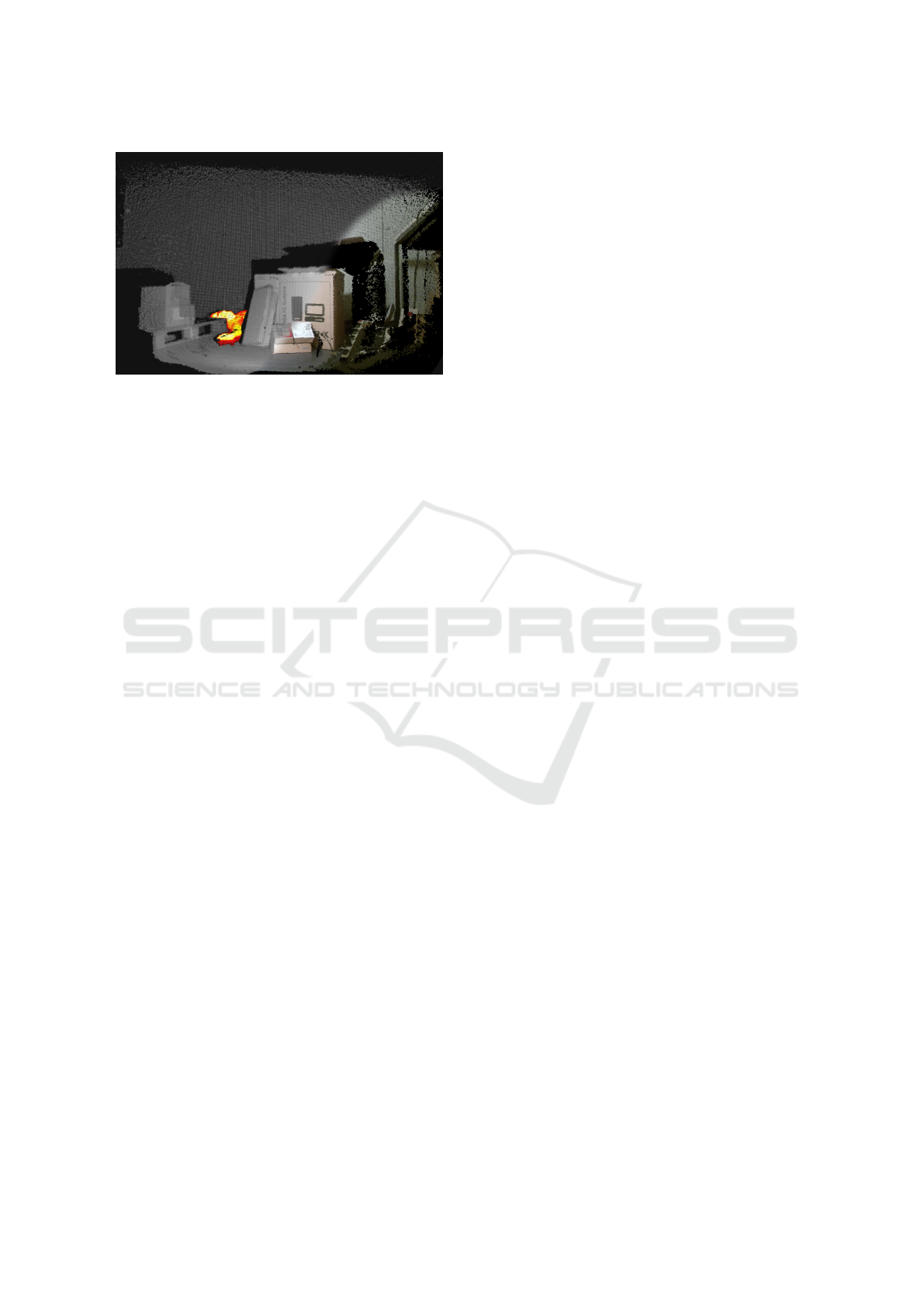
Figure 1: Multi-sensor 3D mapping can help rescue forces
to get a better awareness of the situation.
the mathematical background for 2D-to-3D projec-
tion. Following, the full parallel implementation of
the algorithm is described. Section 4 provides a prac-
tical implementation of the described approach and
presents results of the mapping process. The paper
ends with an evaluation of the shown method fol-
lowed by a final conclusion and an outlook on further
work.
2 RELATED WORK
Besides operating robots in SAR scenarios, teleoper-
ation is used in varying applications (Cui et al., 2003)
such as space (Stoll et al., 2009), undersea (Ridao
et al., 2007) or medical robotics. Simple teleoperat-
ing systems are based on monocular RGB cameras
displayed on two-dimensional screens (Hainsworth,
2001). The operated robot is usually equipped with
either a single camera or multiple ones (Hainsworth,
2001)(Okura et al., 2013) in order to increase the op-
erator’s field of view. For this reason, omnidirec-
tional cameras are often used to enable the operator
to change the view without causing a delay because
the camera position has to be changed by actuators
(Saitoh et al., 2006). In most applications, additional
information such as sensor data are visualized in a
graphical user interface (GUI) as an overlay or on ad-
ditional displays (Hainsworth, 2001)(Nguyen et al.,
2001).
For humans, moving the head is the natural way
to explore the environment. The first teleopera-
tion approaches using tracked head-mounted displays
(HMD) were based on omnidirectional cameras to
visualize 360
◦
images. Looking at an omnidirec-
tional camera image, the operator still gets only a
two-dimensional impression of the robot environment
with limited perception of depth and scale. Using
monocular cameras, this disadvantage can be com-
pensated by using structure from motion (SFM) tech-
niques as done in (Saitoh et al., 2006). Besides
the application of SFM, multi-camera systems (Yong
et al., 1998) or depth cameras (Okura et al., 2013) are
needed to provide full three-dimensional information
to allow the perception of scale and depth.
The work presented in (Okura et al., 2013) de-
scribes a teleoperation interface enabling an operator
to control a robot from freely configured viewpoints
visualized by a head-mounted display and a head-
tracker. For environmental perception, the robot is
equipped with four structured light (SL)-based depth
cameras. To avoid simulator sickness and to enable
the operator to react fast enough on occurring events,
all delays have to be kept as small as possible.
In contrast to the approach presented in this paper,
the existing virtual reality concepts only use RGB-
D information. Projecting two-dimensional infor-
mation onto three-dimensional structures is useful in
many areas such as entertainment, medical applica-
tions or the building sector. RGB-D mapping us-
ing depth cameras is state-of-the-art in robot appli-
cations as presented in (Henry et al., 2010), (Endres
et al., 2013) and (Izadi et al., 2011). The works pre-
sented in (Vidas et al., 2013), (Vidas and Moghadam,
2013) and (Moghadam and Vidas, 2014) describe a
hand-held device built out of a RGB-D and a ther-
mal camera. The device is used for thermal-to-3D
mapping which is helpful to monitor the energy ef-
ficiency of building structures. From the authors’ per-
spective, the device has neither been implemented on
a mobile robot, nor makes use of GPU-acceleration.
Besides, a GPU suited implementation of the map-
ping procedure is necessary to provide mapped, three-
dimensional structures to ensure low latency for vir-
tual reality applications as presented in this paper. In
contrast to existing approaches, the work presented in
this paper uses multi-sensor data to create a merged
point cloud, which selectively maps different image
sources according to their importance to one output
point cloud.
3 APPROACH
The following section describes the approach used in
this paper to project two-dimensional images from
different cameras onto three-dimensional structures
which are finally visualized by a head-mounted dis-
play. This procedure includes the following steps:
1. Preprocessing and Filtering: The quality of the
final multi-channel point cloud depends on the
ICINCO 2016 - 13th International Conference on Informatics in Control, Automation and Robotics
20

quality of the depth image. Therefore, measure-
ment noise and errors have to be filtered before
mapping and thus appropriate filters have to be
applied.
2. Hybrid Calibration: To perform mapping, it is
necessary to determine the camera parameters to
remove lens distortion. For the mapping pro-
cess, the homogeneous transformation between
the used sensor coordinate systems need to be
known. Consequently, corresponding points have
to be identified in the sensor images. As a result
of varying working principles of the sensors (e.g.
RGB and thermal), a special calibration pattern is
necessary to identify corresponding points.
3. Time Synchronization: To reduce the mapping
error based on time differences due to varying
measurement rates, messages are filtered accord-
ing to their time stamp.
4. Parallel Mapping: The pixels of the filtered and
intrinsic calibrated depth image are used to gen-
erate a set of three-dimensional points, the two-
dimensional images can be mapped on. Based
on the performed extrinsic calibration, the point
cloud is transformed into the coordinate system
of the two-dimensional camera as preparation for
the mapping. Then the image is projected onto
the point cloud. Parallely, the mapping procedure
is performed on the GPU.
5. Selective Mapping: The mapped point clouds are
then merged to a single one, in which the most
relevant information of all mapped input images
are visualized. This step includes the highlighting
of hidden persons by the thermal image and illu-
minating dark regions in the RGB image by the
active infrared image.
Sections 3.1 to 3.6 are structured according to the pre-
sented order of steps.
3.1 Preprocessing
To increase the quality of the mapped three-
dimensional model and to avoid mapping errors, it is
important to preprocess the depth image which is typ-
ically affected by measurement noise and errors.
To prevent an error prone projection caused by im-
age noise in the depth image, the depth image is fil-
tered using a bilateral filter as described in (Tomasi
and Manduchi, 1998). In contrast of a box, bilinear
or Gaussian filter, by using a bilateral filter, the sur-
faces of the object are smoothed preserving edges at
the same time due to an additional range component.
To remove single measuring errors appearing as
outliers in the free space (therefore often referenced to
as flying pixels), a threshold filter is applied based on
the average distance of the surrounding pixels which
are unequal to zero. The mean distance can be deter-
mined according to:
p(i, j) =
1
u
∑
l,m
|| f (i, j) − k(l, m)||
2
(1)
and
k(l, m) =
f (l, m), for f (l, m) 6= 0
f (i, j), else
, (2)
Where u is the number of surrounding pixels for that
k(l, m) is unequal to zero. With the threshold θ, the
final value of the filtered depth image depth(i, j) is
given through:
g(i, j) =
f (i, j), for p(i, j) < θ
0, else
. (3)
3.2 Hybrid Calibration
Like any other camera, depth, thermal or RGB cam-
eras are affected by lens distortion and inaccuracies
during production and therefore need to be intrinsi-
cally calibrated. Before sensor data can be projected,
the cameras need to be extrinsically calibrated also.
State-of-the-art calibration techniques for traditional
two-dimensional cameras are presented in (Brown,
1971), (Zhang, 1999) and (Zhang, 2000). Consider-
ing that typical two-dimensional calibration patterns
are unsuited for thermal and depth calibration, a hy-
brid calibration pattern is presented in this section,
which enables multi-sensor to depth calibration for a
variety of imaging techniques.
Regarding the different working principles of the
used sensors, the calibration pattern used for the cal-
ibration of a specific camera varies. For the intrinsic
calibration of a RGB camera, a typical printed black
and white chessboard provides points in the pattern
coordinate system which can be identified in the cam-
era image. By using a strong infrared light source,
the same pattern can be used to calibrate the active
infrared camera. Since the temperature of a printed
pattern is equally distributed over the pattern after all
balancing processes are completed, it is not possible
to identify the necessary amount of calibration points
in the thermal image using a printed pattern. To solve
this issue, heaters can be applied at dedicated po-
sitions in the calibration pattern coordinate systems
to identify corresponding points for calibration pur-
poses. In case of ToF cameras, the amplitude image
(active infrared) can be used for intrinsic calibration
GPU-accelerated Multi-sensor 3D Mapping for Remote Control of Mobile Robots using Virtual Reality
21
based on the working principle of ToF. Besides using
the infrared image, it is also possible to create a chess-
board, where every square of the chessboard varies in
height and thus providing points in the calibration pat-
tern that can be identified by depth.
If the same calibration pattern is visible in two dif-
ferent camera images at the same time, the transfor-
mation between each camera and the chessboard can
be used to compute the transformation between both
camera coordinate systems. This requires, that at least
N = 3 points of the pattern given in the chessboard co-
ordinate system can be identified in both images at the
same time.
According to this constraint, considering the dif-
ferent working principles of depth, IR, RGB and ther-
mal cameras, a typical black and white calibration
pattern is unsuited for an extrinsic calibration. For ex-
ample, in the image of the thermal camera, the printed
structure of the pattern would look uniform based on
the same temperature and material of the chessboard
and could not be identified. The remaining difference
in the thermal image based on the different emissiv-
ity of the black and the white color is not sufficiently
large for a calibration as needed for high accurate sen-
sor mapping. A similar issue takes effect for the depth
image, where corresponding points would look uni-
formly based on a similar depth.
To be able to identify at least three correspond-
ing points in the camera images, a hybrid chessboard
pattern needs to be designed, in which the black and
the white squares differ in material, temperature and
depth. If the depth camera can be calibrated using an
intensity image as described in this section, the pat-
tern does not need to vary regarding depth. For this
purpose, the pattern needs to be built out of different
materials as plastic and metal, whereas one color is
heated to a constant temperature difference. The the-
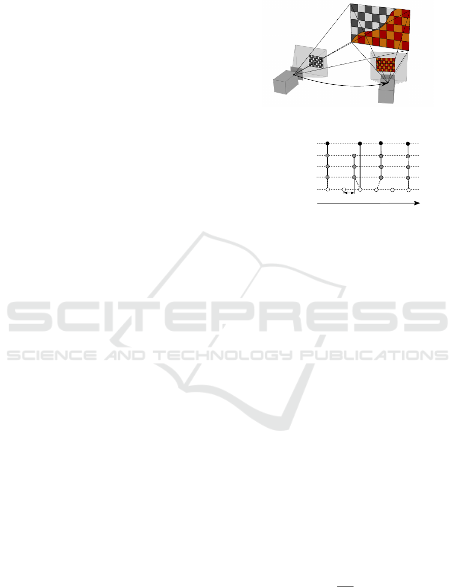
oretical setup for such a calibration is shown in Figure
2.
Figure 2 shows a RGB and a thermal camera look-
ing at a hybrid calibration pattern where every square
of the chessboard distinguishes in color and tempera-
ture. The transitions between the chessboard squares
can be identified in the RGB image because of the
variation in color. In contrast, the transitions in the
thermal image can be identified based on the varia-
tion in temperature caused by the heat pads attached
to the background of the squares. To prevent the heat
to spread through the pattern, the squares have to vary
regarding their thermal conductivity to ensure clear
temperature transitions in the thermal image.
The computed transformation between two cam-
eras is limited in accuracy by the camera resolution
THERMAL-C
T
RGB-C
(CS)
RGB-C
(CS)
THERMAL-C
Figure 2: Heated calibration pattern for extrinsic calibration
of RGB and thermal camera.
Depth (30Hz)
RGB (30Hz)
IR (30 Hz)
Thermal (50Hz)
Time
Resulting Signal
Δt
Figure 3: Synchronization of cameras working at asyn-
chronous measurement rates.
and disturbance variables such as image noise. To de-
crease the error of the resulting transformation, the
transformation is computed for an array of coinci-
dent images. To find the local minimum of the repro-
jection error for the transformation, the Levenberg-
Marquardt iterative algorithm is used for optimiza-
tion. The realization of the hybrid calibration pattern
is presented in Section 4.2.
3.3 Time Synchronization
Even if the sensors are synchronized regarding a
global system time, measurement updates are typi-
cally occurring at different measurement rates. To
reduce resulting mapping errors as they would occur
when depth images are registered to data from a dif-
ferent time, the time difference has to be kept as small
as possible.
Figure 3 shows four input signals at different mea-
surement rates of 30 Hz and 50 Hz.
The depth, RGB and IR camera are working time-
synchronized at f
d
= f
RGB
= f
IR
= 30 Hz, the mea-
surement rate of the thermal camera differs with a
measurement rate of f
th
= 50 Hz. The maximum time
difference ∆t
max
between a depth, RGB or IR mea-
surement and a thermal measurement is defined by the
faster measurement rate of the thermal camera f
th
:
∆t
max
=
1
2 f
th
= 10 ms. (4)
If ∆t between two succeeding measurements is less
or equal ∆t
max
, the messages are used for mapping.
If ∆t > ∆t
max
, the first measurement is discarded and
ICINCO 2016 - 13th International Conference on Informatics in Control, Automation and Robotics
22

the time measurement is repeated for the second mea-
surement.
The resulting update rate for the synchronized sig-
nal f
rs
varies according to Equation 5 and has an up-
per bound given by the measurement rate of the depth
camera f
d
.
f
d
≥ f
rs
≥
1
1
f
d
+
1
2 f
th
. (5)
3.4 Mapping
The equation for projecting a point from the physi-
cal world into the camera image plane can be used
to reconstruct a three-dimensional point
(d)
X
p
given
(I
d
)
x
p
, the associated point in the image plane in a
filtered and intrinsic calibrated depth image (I
d
) (see
Section 3.1) by inverting M as shown in Equation 6.
(d)
X
p
=
(d)
M
−1
(I
d
)
˜
x
p
. (6)
The two dimensional point
(I
d
)
˜
x
p
is given as homoge-
neous vector where
(I)
x
p
and
(I)
y
p
are the screen coor-
dinates, starting in the upper left corner of the image.
(I
d
)
˜
x
p
=
(I
d
)
x
p
(I
d
)
y
p
(I
d
)
w
p
T
, (7)
where
(I
d
)
w
p
in
(I
d
)
˜
x
p
is given by the depth value in
the depth image according to
(I
d
)
w
p
=
(d)
Z
p
= d(
(I
d
)
x
p
,
(I
d
)
y
p
)s
d
. (8)
The inverse
(d)
M
(−1)
can be computed as follows:
(d)
M
(−1)
=
1
(d)
f
x
(d)
f
y
(d)
f
y
0 −
(d)
c
x
(d)
f
y
0
(d)
f
x
−
(d)
c
y
(d)
f
x
0 0
(d)
f
x
(d)
f
y
,
(9)
In Equation 8, s
d
is the scale factor, which relates the
depth value in the depth image to
(d)
Z
p
the depth in
the camera coordinate system of the depth camera.
Using Equations 6 to 8, the coordinates of a three-
dimensional point in the depth camera’s coordinate
system can be computed for every two-dimensional
point in screen coordinates of the depth image. By
upscaling the depth image and therefore the quantity
of pixels which can be registered to 3D points.
To perform a mapping between a calibrated two-
dimensional image of a camera c and the generated set
of three-dimensional points, every point given in the
point cloud
(d)
e
X
p
needs to be transformed into the co-
ordinate system of the camera c. This can be done us-
ing the extrinsic calibration described in Section 3.2:
(c)
e
X
p
=
c
T
d
(d)
e
X
p
. (10)
To complete the mapping of a point
(c)
e
X
p
given
in the corresponding coordinate system of a two-
dimensional camera, the point needs to be projected
onto the image plane of the camera c.
(I
c
)
˜
x
p
=
(c)
M
(c)
e
X
p
. (11)
The color of the three dimensional point is given by
the color of the image point
(I
c
)
x
p
. After merging the
point cloud and the image source, the point cloud is
retransformed to the depth camera coordinate system:
(d)
e
X
p
=
d
T
c
(c)
e
X
p
. (12)
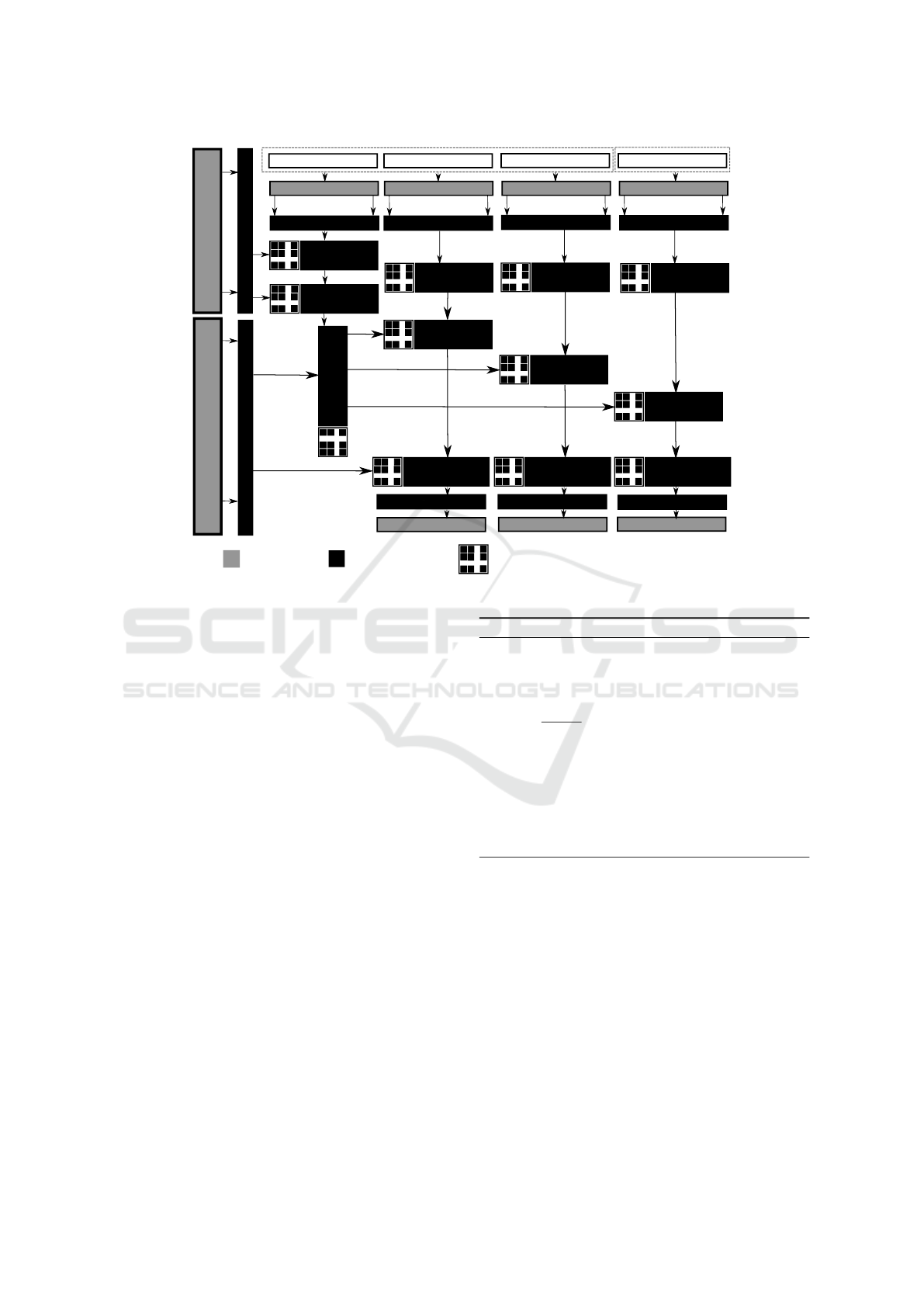
3.5 Parallelization
The parallelized mapping procedure is presented in
figure 4.
The mapping procedure is separated into code,
which is executed on the CPU (host) and code which
is executed in parallel on the GPU (device). There-
fore, the data necessary to perform the computations
for mapping need to be transferred between host and
device memory to be processed. Because host-to-
device and device-to-host copies are time consum-
ing and increase computation time (compared to CPU
based approaches, where all data already are on the
device they are processed on), it is necessary to keep
them to a minimal number.
For this reason, the extrinsic and intrinsic calibra-
tion parameters are transferred once during initializa-
tion and are kept in GPU memory. After time syn-
chronization, corresponding data are loaded in the
host memory. Before parallel processing, they are
transferred to the device memory, which has been al-
located during initialization. Because the resolution
of the depth, RGB, IR and thermal image is known a
priori, the size of the allocated memory is static. Dur-
ing runtime, multiple copies of the program can be
executed in parallel on GPU blocks. Because every
point of the point cloud can be independently com-
puted based on the filtered depth image, the compu-
tation is performed in parallel on a fixed number of
blocks given by the resolution of the depth image.
According to Section 3.4, after point cloud genera-
tion, the points are transformed according to the ex-
trinsic relation of the cameras and subsequently pro-
jected into the image plane. Because the amount of
computations in these steps is high but the involved
calculations are simple and are independent of each
other, these steps are also well suited to be performed
in parallel blocks on the GPU. After inverse transfor-
mation, the point cloud is written into the host mem-
ory for visualization. To optimize the mapping du-
ration further, the practical implementation deviates
GPU-accelerated Multi-sensor 3D Mapping for Remote Control of Mobile Robots using Virtual Reality
23
CPU (host)
GPU (device)
Depth Image
IR-Image
RGB-Image
Thermal-Image
Device Memory
Host Memory Host Memory Host Memory Host Memory
Intrinsic Calibration
Parameters
Extrinsic Calibration
Parameters
Device Memory
Device Memory
Host-to-Device copy
Host-to-Device copy
Host-to-Device copy
Device Memory
Device Memory
Device Memory
Parallel performed operation
...
...
...
...
...
...
...
...
...
...
Point Cloud
generation
...
...
...
...
...
Undistortion
...
...
...
...
...
...
...
...
...
...
Undistortion
Undistortion
...
...
...
...
...
Point Cloud
transformation
...
...
...
...
...
Projection
...
...
...
...
...
Projection
...
...
...
...
...
Projection
...
...
...
...
...
Point Cloud
transformation
...
...
...
...
...
Point Cloud
transformation
...
...
...
...
...
Point Cloud
transformation
Device Memory
Device Memory
Device Memory
Host Memory
Host Memory
Host Memory
Host-to-Device copy
Host-to-Device copy
Host-to-Device copy
...
...
...
...
...
Filtering
Figure 4: Overview of the software architecture.
from the procedure presented in figure 4 and is only
performed for the selected output point cloud. There-
fore, the number of host-to-device and device-to-host
copies during runtime is decreased from 7, which are
necessary to provide mapping for all point clouds, to
3. Excluded from this number are the host-to-device
copies of the extrinsic and intrinsic calibration param-
eters, which have only to be performed once on start.
3.6 Selective Mapping
If all point clouds are selected for mapping in the
previous step, a selective mapping procedure can be
performed, which generated a point cloud, in which
points are mapped according to their importance for
the operator. The algorithm is presented in pseudo-
code below.
To avoid dark regions in the RGB image, dark
points are replaced by the mapped IR points, if the
brightness is below a given threshold. Subsequently,
noticeable regions in the thermal image are mapped
with priority to the point cloud, if they exceed a pre-
defined threshold to highlight buried persons or hot
regions which could be dangerous for the robot.
Algorithm 1: Selective Point Cloud Fusion.
Input: RGBD-, IRD-, THERMAL-Point Cloud
Output: Multi-Sensor Point Cloud
1: Initialize Output Point Cloud P
2: for each Point p in Point Cloud P do
3: if (
R+G+B
3
) < brightnessTresh then
4: P = IR
5: end if
6: if T HERMAL > thermalTresh then
7: P = THERMAL
8: end if
9: end for
10: return P
4 EXPERIMENTS
The following section describes the experimental
setup which is used to evaluate the results of Sec-
tion 3.
4.1 Experimental Setup
For evaluation purposes, a Pioneer 2 mobile robot
has been equipped with a FLIR A655sc thermal cam-
era (640 x 480 @ 50 f ps) and a Microsoft Kinect v2
depth-sensing camera providing RGB (1920 x 1080
ICINCO 2016 - 13th International Conference on Informatics in Control, Automation and Robotics
24
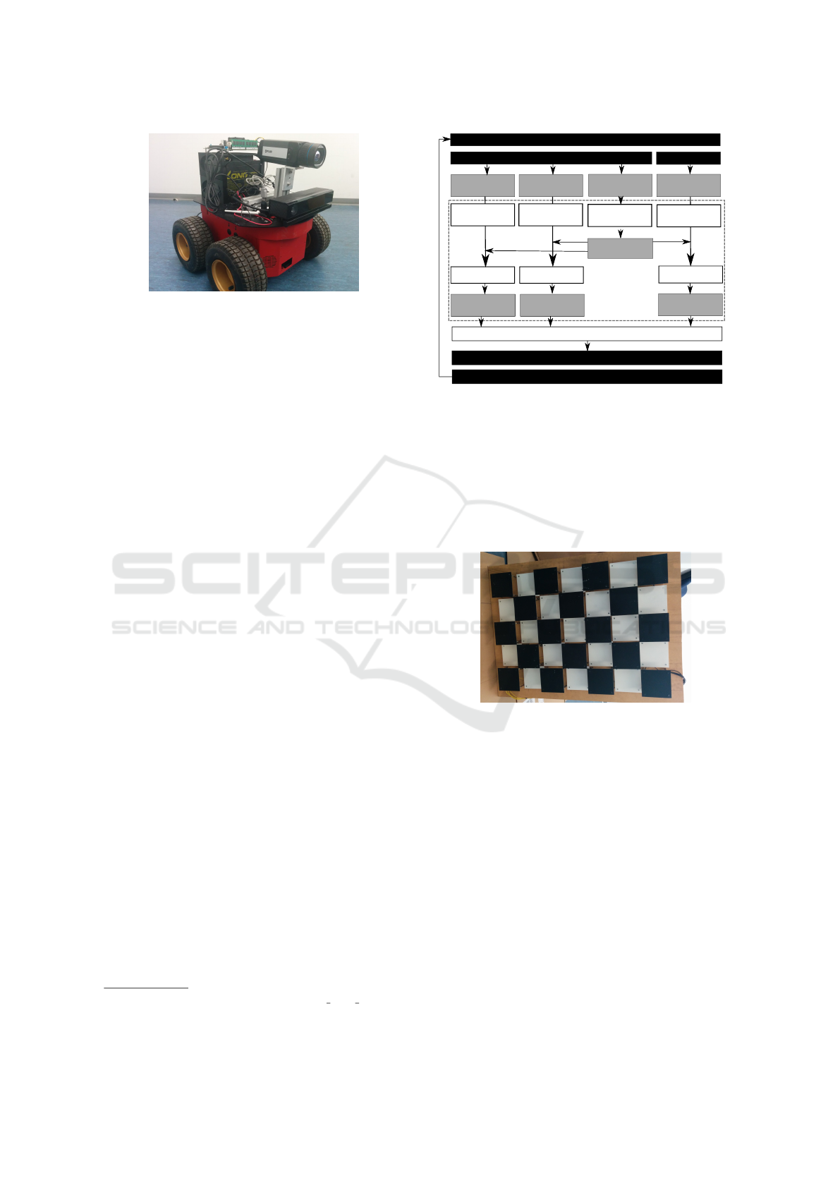
Figure 5: Pioneer 2 mobile robot equipped with a Microsoft
Kinect v2 depth-sensing camera and a FLIR A655sc ther-
mal camera.
@ 30 f ps), depth (512 x 424 @ 30 f ps) and active
IR images (512 x 424 @ 30 f ps). In contrast to the
Kinect 1, which is based on structured light to esti-
mate depth, the Kinect 2 collects depth information
based on ToF measurements. To enable extrinsic cal-
ibration, both cameras are rigidly mounted on the Pi-
oneer as shown in Figure 5.
The sensor data are prompted and compressed on-
board by a KTQM87 mITX board with an Intel quad
core i7 CPU and 16 GB RAM running Ubuntu 14.04
64-bit. To power the Pioneer 2 and the connected
sensors, the standard power supply is replaced with
a 12 V 50 Ah car battery.
The compressed information is then transmitted
via WiFi to a PC with an Intel quad core i5-4570 CPU,
16 GB RAM and a GeForce GTX 970 GPU. Sub-
sequently, the data are preprocessed and registered
according to Section 3. The resulting multi-channel
point cloud is visualized using RViz. To render the
stereo images for the Oculus Rift, the Oculus Rviz
Plugin has been used
1
. The data are displayed to the
operator using an Oculus Rift Developer Kit 2 by Ocu-
lus VR. The head movement is tracked by the Oculus
Rift and used to move the camera in Rviz. The oper-
ator can control the Pioneer 2 using a Logitech Cord-
less Rumble Pad 2.
Figure 6 gives an overview of the input and output
structure used for the evaluation.
Besides, the intrinsic and extrinsic calibration
which has only to be performed once, all parts of the
presented method are programmed to work in parallel
taking advantage of the GPU.
4.2 Intrinsic and Extrinsic Calibration
To be able to identify corresponding points for cal-
ibration in the RGB, IR, depth and in the thermal
1
https://github.com/ros-visualization/oculus rviz plugins,
June 2015
Microsoft Kinect v2
FLIR A655sc
RGB
IR
DEPTHMAP
THERMAL
(MONO16)
(16UC1)
(16UC1)
(RGB8)
OculusVR Oculus Rift Devkit 2
POINTCLOUD
FILTERING
POINTCLOUD
RGBD-
POINTCLOUD
IRD-
POINTCLOUD
TD-
POINTCLOUD
RGB-
MAPPING
IR-
MAPPING
THERMAL-
MAPPING
RGB-
FILTERING
IR-
FILTERING
THERMAL-
FILTERING
3D VISUALIZATION
Pioneer 2
Logitech Cordless RumblePad 2
Compare Figure 4
Figure 6: Overview of the input and output structure.
image as mentioned in Section 3.2, a hybrid chess-
board pattern has been designed for calibration, in
which the black and the white squares differ in color,
depth, material and temperature. For this purpose, the
black squares are made of metal, which is electrically
heated to a constant temperature, whereas the white
squares are made out of plastic. The pattern used for
calibration is shown in Figure 7.
Figure 7: A three-dimensional, heated calibration pattern
for thermo-depth calibration.
Besides the differences in temperature, the black
and white chessboard squares also differ in depth. Be-
cause the depth image also provides intensity images
(active IR), the depth differences were not used for
depth camera calibration. The size of one square is
100 mm x 100 mm with a depth difference between a
black and a white square of 40 mm.
4.3 Mapping
The results of the mapping process are shown in Fig-
ure 8(a) to 8(l).
The first image of every row shows the raw, un-
registered point cloud which is generated according
to Section 3.4. The following figures are showing the
point cloud registered to RGB, active IR and thermal
GPU-accelerated Multi-sensor 3D Mapping for Remote Control of Mobile Robots using Virtual Reality
25
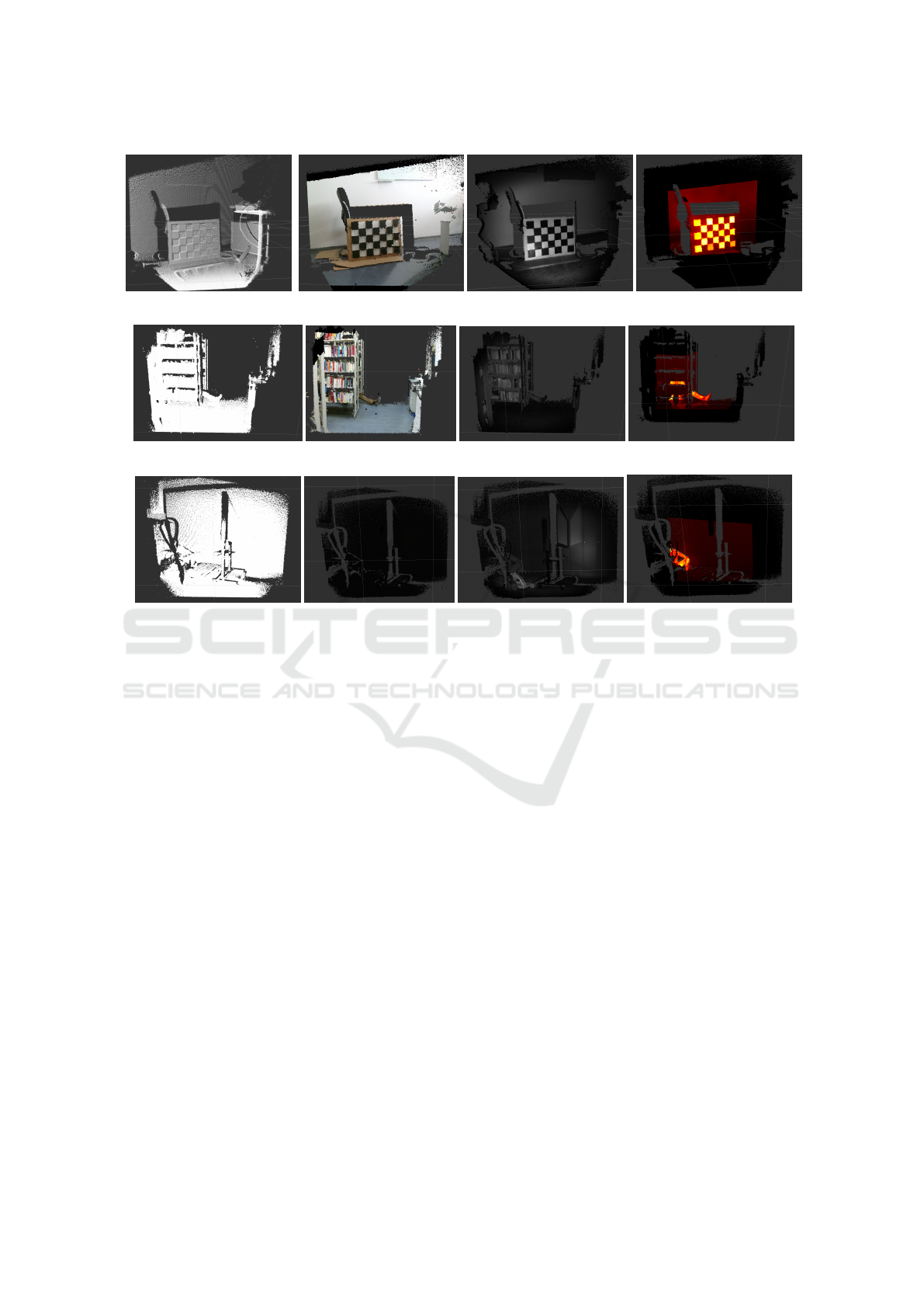
(a) Pure depth (b) RGB-D (c) IR-D (d) THERMAL-D
(e) Pure depth (f) RGB-D (g) IR-D (h) THERMAL-D
(i) Pure depth (j) RGB-D (k) IR-D (l) THERMAL-D
Figure 8: Final mapping results for different scenes: (a) to (d) Different image sources mapped onto the calibration pattern
(e) to (f) Person hidden behind a bookshelf, (g) to (h) Person lying in the edge of a dark storage room.
images. To illustrate the advantages of the different
sensors, each row shows a different scenario:
Figure 8(h) shows uncolored, black points in the
outer region of the point cloud caused by varying field
of views of the depth and the thermal camera. Be-
cause the thermal camera has a smaller vertical and
horizontal field of view, the thermal image provides
no information which could be mapped to the outer
points of the point cloud. Because of the high num-
ber of points, surfaces and small details can be recog-
nized.
5 RESULTS
The following section evaluates the results of the pre-
sented approach regarding calibration quality and pro-
cessing time.
5.1 Calibration
The cameras have been calibrated using the calibra-
tion pattern described in Section 4.2. For calibra-
tion, 40 images have been made from different poses
around the calibration pattern with every camera. The
results of the intrinsic calibrations are shown in Ta-
ble 1. The distortion parameters for lens distortion
removal are not listed in Table 1.
The quality of the calibration can be evaluated
based on the resulting root mean square reprojection
error (rms), which is calculated for the images made
after applying the intrinsic calibration. Based on the
total pattern size of 700 mm x 500 mm, the pattern
was unsuited to be placed in the near field in front of
the camera depending on the camera’s field of view
which affects the quality of the calibration.
The calibration of the IR camera got a higher rms
compared to the RGB calibration, probably because
the chessboard points could not be reliably detected
in the whole field of view due to the limited IR light-
ning in the outer regions of the image. Additionally,
the IR image is stronger affected by image noise com-
pared to the RGB image. Furthermore, the resolution
of the IR camera is smaller than the resolution of the
RGB camera which reduces the accuracy of the de-
tected points.
The rms of the thermal camera is higher than the
ICINCO 2016 - 13th International Conference on Informatics in Control, Automation and Robotics
26
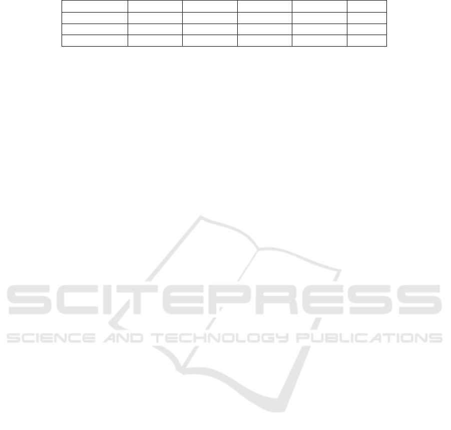
Table 1: Results of the intrinsic calibration (without distortion parameters).
Camera f
x
[px] f
y
[px] c
x
[px] c
y
[px] rms
RGB 1.063e+03 1.066e+03 9.59e+02 5.541e+02 0.1734
IR and Depth 3.633e+02 3.631e+02 2.442e+02 2.030e+02 0.6856
Thermal 7.984e+02 7.997e+02 3.140e+02 2.371e+02 1.0351
rms of the RGB and the IR camera. This may be
caused by the fixed focus which has been used for cal-
ibration, providing a lower range where objects are in
focus compared to the IR camera. This leads to blur
and consequently to inaccuracy detecting the chess-
board points. The results of the extrinsic calibration
regarding the rms are presented in Table 2.
Based on the results of the mapping, the rms of
the extrinsic calibration can be considered as suffi-
cient for visualization.
5.2 Processing Time
To avoid simulator sickness and to enable the opera-
tor to react fast on occurring events, all delays have
to be kept as small as possible. Therefore, the pre-
sented algorithm has been implemented using Com-
pute Unified Device Architecture (CUDA) to operate
on a NVIDIA GTX 970 GPU with 1664 cores. The
CUDA-based GPU implementation is compared with
a single core CPU implementation. Table 3 gives an
overview of the average processing time of 10, 000
frames for the presented algorithm performed on the
CPU and the GPU. The processing time on the GPU
has been measured using the CUDA event API; the
processing time of the CPU version has been mea-
sured using clock ticks elapsed since the algorithm
has been started divided by the clocks per second.
The highest acceleration could be archived by im-
plementing the preprocessing step on the GPU (which
includes bilateral filtering and flying pixel detection
as described in Section 3.1). The preprocessing step
could be accelerated by 112, 43 ms which is an ac-
celeration of 85.37 % referred to the former duration
which makes 97.88 % of the total acceleration.
Using the GPU implementation, the complete
mapping process could be accelerated by 80.03 %
compared to the CPU implementation which is an ac-
celeration of 114.73 ms. While the processing rate
of the CPU implementation limits the possible frame
rate to 7 f ps, the GPU implementation allows a frame
rate of 35.59 f ps. Because the frame rate is limited to
30 f ps by the depth camera, the new processing time
of 28.84 ms can be considered to be sufficient. To
perform the mapping on the GPU, all necessary data
need to be copied to the GPU memory for processing.
After processing has been completed, the data need
to be copied back to be accessible by the CPU. The
time needed for allocation, deallocation and copying
has been pooled as Memory Operations in Table 3.
5.3 Limitations
Like all ToF cameras, the Kinect v2 can be affected
by direct sunlight outshining the light emitted by the
ToF camera. To evaluate the performance of the pre-
sented approach, the setup has been tested indoor in a
controlled environment. For this reason the approach
presented in this paper is limited to applications with
no direct sunlight. There are, however, ToF cameras
available with additional light sources which are con-
firmed to be suited for outdoor application as the OI-
VS-1000 produced by ODOS Imaging.
6 CONCLUSION AND FURTHER
WORK
In this paper, a new VR control concept for oper-
ating robots in SAR scenarios has been introduced.
The presented approach intuitively visualizes differ-
ent sensor signals as RGB, thermal or infrared images
by merging them with 3D data generated by a ToF-
based depth camera. The three-dimensional point
cloud is then visualized on a tracked head-mounted
display to provide the additional information. The
approach has been evaluated under laboratory condi-
tions using a Pioneer 2 mobile robot equipped with a
depth, RGB, IR and thermal camera.
For intrinsic and extrinsic calibration, a new cal-
ibration pattern has been introduced. It has been
shown, that the presented calibration pattern is well
suited for multi-sensor calibration with acceptable
root mean square reprojection errors.
To avoid simulator sickness and decrease the re-
action time of the operator, the multi-sensor mapping
has been performed on a GPU. It has been shown, that
performing the mapping on the GPU can significantly
decrease the processing time by about 80 % compared
to traditional CPU implementation consequently de-
creasing the delay. It must be taken into account, that
the GPU version had been compared against a single
threaded CPU implementation. The relative accelera-
GPU-accelerated Multi-sensor 3D Mapping for Remote Control of Mobile Robots using Virtual Reality
27
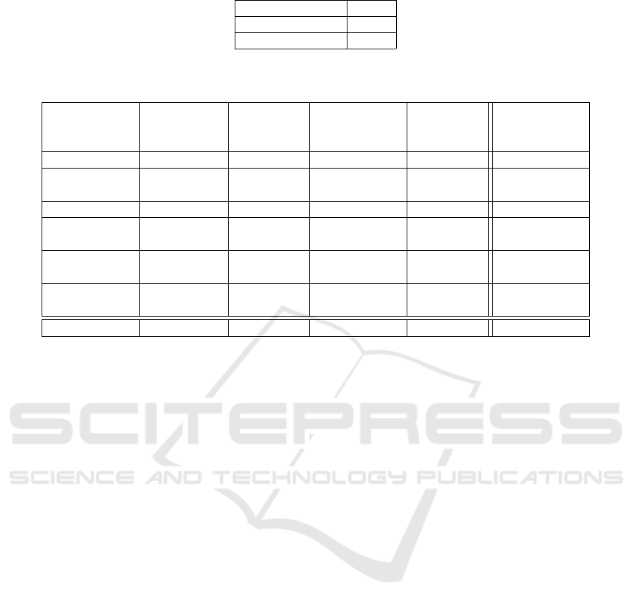
Table 2: Results of the extrinsic calibration.
Transformation rms
RGB - Depth 0.323
Thermal - Depth 1.019
Table 3: Comparison between the processing time performing the mapping for one image as CPU and GPU implementation.
Average value of 10,000 processing steps with a depth image resolution of 512x424.
Step Average
Time CPU
[ms]
Percentage
of Total
[%]
Average
Time GPU
[ms]
Percentage
of Total
[%]
Acceleration
[%]
Preprocessing 131.69 92.20 19.26 68.54 85.37
Point Cloud
Generation
4.07 2.8 3.16 8.89 22.36
Transformation 1.13 0.79 0.60 2.10 46.90
Image Plane
Projection
4.80 3.34 3.22 8.73 32.92
Inverse Trans-
formation
1.14 0.79 0.60 2.10 47.37
Memory Op-
erations
- - 1.26 4.5 -
Total 142.83 100 28.1 100 80.03
tion of the GPU implementation would decrease com-
pared against a fully optimized, multi-threaded CPU
version of the mapping procedure. To verify the ex-
pected reduction of simulator sickness and resultant
fatigue, additional experiments in real-life conditions
still need to be performed.
The presented approach has been evaluated in a
lab scenario. To prove the effectiveness of the new
control approach compared to traditional control con-
cepts, the system needs to be evaluated in real SAR
scenarios.
The overview of the surrounding structures can be
further improved by building an environmental map
registering the multichannel scans. For such appli-
cations, the multichannel point cloud can be used to
increase the robustness of correspondence identifica-
tion for scan registration to avoid ambiguity in scan
images.
To increase the quality for the intrinsic and extrin-
sic calibration, the field size of the calibration pattern
could be reduced to be able to calibrate the camera in
the near region. It should be examined, whether hap-
tic feedback would lead to a further improvement re-
garding the usability aspects for untrained operators.
Moreover, the mapped sensor data could be used to
improve information models as presented in (Gernert
et al., 2014) with additional information layers. The
mapping of thermal images onto three-dimensional
structures is useful for improved temperature estima-
tion as presented in (Zeise et al., 2015).
REFERENCES
Brown, D. C. (1971). Close-range camera calibration.
In Photogrammetric Engineering, volume 37, pages
855–866.
Cui, J., Tosunoglu, S., Roberts, R., Moore, C., and Rep-
perger, W. (2003). A review of teleoperation system
control. In Florida Conference on Recent Advances
in Robotics (FCRAR), pages 1–12, Boca Raton, FL,
USA.
Endres, F., Hess, J., Sturm, J., Cremers, D., and Burgard,
W. (2013). 3D mapping with an RGB-D camera. vol-
ume 30, pages 177–187.
Gernert, B., Schildt, S., L.Wolf, Zeise, B., Fritsche, P.,
Wagner, B., M.Fiosins, Manesh, R., and Mueller, J.
(2014). An interdisciplinary approach to autonomous
team-based exploration in disaster scenarios. In IEEE
International Symposium on Safety, Security, and Res-
cue Robotics (SSRR), pages 1–8, Hokkaido, Japan.
Hainsworth, D. W. (2001). Teleoperation user interfaces for
mining robotics. In Autonomous Robots, volume 11,
pages 19–28, Hingham, MA, USA.
Henry, P., Krainin, M., Herbst, E., Ren, X., and Fox, D.
(2010). RGB-D mapping: Using depth cameras for
dense 3d modeling of indoor environments. In RGB-
D: Advanced Reasoning with Depth Cameras Work-
shop in conjunction with RSS, Zaragoza, Spain.
Izadi, S., Kim, D., Hilliges, O., Molyneaux, D., Newcombe,
R., Kohli, P., Shotton, J., Hodges, S., Freeman, D.,
Davison, A., and Fitzgibbon, A. (2011). Kinectfu-
sion: Real-time 3d reconstruction and interaction us-
ing a moving depth camera. In ACM Symposium on
User Interface Software and Technology, pages 559–
268, Santa Barbara, CA, USA.
ICINCO 2016 - 13th International Conference on Informatics in Control, Automation and Robotics
28

LaValle, S. M., Yershova, A., Katsev, M., and Antonov, M.
(2014). Head tracking for the oculus rift. In IEEE
International Conference on Robotics and Automation
(ICRA), pages 187 – 194, Hong Kong, China.
Moghadam, P. and Vidas, S. (2014). Heatwave: The next
generation of thermography devices. In International
Society for Optical Engineering (SPIE), volume 9105,
page 91050.
Nguyen, L., Bualat, M., Edwards, L., Flueckiger, L., Neveu,
C., Schwehr, K., Wagner, M., and Zbinden, E. (2001).
Virtual reality interfaces for visualization and control
of remote vehicles. Autonomous Robots, 11(1):59–68.
Okura, F., Ueda, Y., Sato, T., and Yokoya, N. (2013). Tele-
operation of mobile robots by generating augmented
free-viewpoint images. In IEEE and RSJ International
Conference on Intelligent Robots and Systems (IROS),
pages 665–671, Tokyo, Japan.
Ridao, P., Carreras, M., Hernandez, E., and Palomeras,
N. (2007). Underwater telerobotics for collabora-
tive research. In Ferre, M., Buss, M., Aracil, R.,
Melchiorri, C., and Balaguer, C., editors, Advances
in Telerobotics, volume 31 of Springer Tracts in Ad-
vanced Robotics, pages 347–359. Springer Berlin Hei-
delberg.
Saitoh, K., Machida, T., Kiyokawa, K., and Takemura, H.
(2006). A 2D-3D integrated interface for mobile robot
control using omnidirectional images and 3d geomet-
ric models. In IEEE and ACM International Sym-
posium on Mixed and Augmented Reality (ISMAR),
pages 173–176, Washington, DC, USA.
Stoll, E., Wilde, M., and Pong, C. (2009). Using virtual
reality for human-assisted in-space robotic assembly.
In World Congress on Engineering and Computer Sci-
ence, volume 2, San Francisco, USA.
Tomasi, C. and Manduchi, R. (1998). Bilateral filtering for
gray and color images. In IEEE International Con-
ference on Computer Vision (ICCV), pages 839–846,
Washington, DC, USA.
Vidas, S. and Moghadam, P. (2013). Heatwave: A hand-
held 3D thermography system for energy auditing. In
Energy and Buildings, volume 66, pages 445 – 460.
Vidas, S., Moghadam, P., and Bosse, M. (2013). 3D thermal
mapping of building interiors using an RGB-D and
thermal camera. In IEEE International Conference on
Robotics and Automation (ICRA), pages 2311–2318,
Karlsruhe, Germany.
Yong, L. S., Yang, W. H., and Jr, M. A. (1998). Robot task
execution with telepresence using virtual reality tech-
nology. In International Conference on Mechatronic
Technology, Hsinchu, Taiwan.
Zeise, B., Kleinschmidt, S. P., and B.Wagner (2015). Im-
proving the interpretation of thermal images with the
aid of emissivity’s angular dependency. In IEEE Inter-
national Symposium on Safety, Security, and Rescue
Robotics (SSRR), pages 1–8, West Lafayette, Indiana,
USA.
Zhang, Z. (1999). Flexible camera calibration by viewing
a plane from unknown orientations. In IEEE Inter-
national Conference on Computer Vision, volume 1,
pages 666–673, Kerkyra, Greece.
Zhang, Z. (2000). A flexible new technique for camera cali-
bration. In IEEE Transactions on Pattern Analysis and
Machine Intelligence, volume 22, pages 1330–1334.
GPU-accelerated Multi-sensor 3D Mapping for Remote Control of Mobile Robots using Virtual Reality
29
