
A Simulation-based Methodology to Test and Assess
Designs of Mechatronic Neural Interface Systems
Samuel Bustamante
1
, Juan C. Yepes
1,2
, Vera Z. P
´
erez
2
and Julio C. Correa
1
1
Grupo de Autom
´
atica y Dise
˜
no A+D, Facultad de Ingenier
´
ıa Mec
´
anica,
Universidad Pontificia Bolivariana, Cir. 1 #73-76, B22C, Medell
´
ın, Colombia
2
Grupo de Investigaciones en Bioingenier
´
ıa, Facultad de Ingenier
´
ıa El
´
ectrica y Electr
´
onica,
Universidad Pontificia Bolivariana, Cir. 1 #73-76, B22C, Medell
´
ın, Colombia
Keywords:
Methodology, Neural Interface Systems, Surface Electromyography, Upper Limb Prostheses, Rehabilitation,
Signal Processing, Myoelectric Control.
Abstract:
Neural interface systems (NISs) are widely used in rehabilitation and upper limb prosthetics. These systems
usually involve robots, such as robotic exoskeletons or electric arms, as terminal devices. We propose a
methodology to assess the feasibility of implementing these kind of neural interfaces by means of an online
kinematic simulation of the robot. It allows the researcher or developer to make tests and improve the design
of the mechatronic devices when they have not been built yet or are not available. Moreover, it may be used
in biofeedback applications for rehabilitation. The simulation makes use of the CAD model of the robot, its
Denavit–Hartenberg parameters, and biosignals recorded from a human being. The proposed methodology
was tested using surface electromyography signals acquired from the upper limb of a 25-year-old healthy
male. Both real-time and prerecorded signals were used. The robot simulated was the commercial robotic arm
KUKA KR6. The tests proved that the online simulation can be effectively implemented and controlled by
means of a biosignal.
1 INTRODUCTION
In 2011, the World Health Organization reported that
there were about one billion people worldwide with
some type of disability (World Health Organization,
2011). In the European Union, almost 45 million peo-
ple aged between 15 and 64 years reportedly had a
disability around that same year, which corresponds
to 14.1% of that age group (Eurostat, 2014). In the
United States of America, approximately 1.7 million
people had an amputation in 2008 (National Limb
Loss Center Information, 2008). Ziegler et al. esti-
mated that each year there are 185,000 new amputees
of an upper or lower limb. They also presented an esti-
mation of 3.6 million of people living with the loss of
a limb by the year 2050 (Ziegler-Graham et al., 2008).
Continuous search for engineering solutions with
the purpose of helping people experiencing physi-
cal disabilities or suffering deficit on the expression
of cognitive experiences, has led to the development
of artificial neural interfaces (Garc
´
ıa Quiroz et al.,
2007). Furthermore, the research to develop sys-
tems to help and assist restoration of sensory function,
communication and control to impaired humans has
brought new branches of experimental neuroscience
such as neural prostheses, neural interface systems
(NISs) and brain-machine interfaces (BMIs) (Hat-
sopoulos and Donoghue, 2009).
NISs are considered bidirectional transduction
systems that enable the direct contact between a de-
vice and a neurological structure. They are composed
of electrodes (or sensors), cables, data acquisition cir-
cuitry, and an effector system control unit (Garc
´
ıa
Quiroz et al., 2007). The main goal of NISs research
is to connect the nervous system to the outside world.
This connection can be achieved either by stimulat-
ing or by recording electric activity from neural tis-
sue to treat or to assist people with motor, sensory
or other neuronal function disabilities. The systems
that record electric activity from the neural tissues
are called output NISs, and are now migrating from
research proof of concepts and pilot human clinical
trials to useful devices (Hatsopoulos and Donoghue,
2009). Some of the most studied devices are neural
prostheses, exoskeletons and telemetry robots (Garc
´
ıa
Quiroz et al., 2007).
Robotic devices, therefore, can be used to improve
the quality of life of human beings. Some of these
78
Bustamante, S., Yepes, J., Pérez, V. and Correa, J.
A Simulation-based Methodology to Test and Assess Designs of Mechatronic Neural Interface Systems.
DOI: 10.5220/0005698200780087
In Proceedings of the 9th International Joint Conference on Biomedical Engineering Systems and Technologies (BIOSTEC 2016) - Volume 4: BIOSIGNALS, pages 78-87
ISBN: 978-989-758-170-0
Copyright
c
2016 by SCITEPRESS – Science and Technology Publications, Lda. All rights reserved

robots can be considered robotic arms, and are similar
to serial manipulators. These devices consist of open-
loop kinematic chains, i.e., open-loop assemblies of
rigid bodies (links) connected by joints (Tsai, 1999).
Exoskeletons with three degrees of freedom are ex-
amples of these kind of robots.
The scope of this paper is to present a four-step
methodology that can be used to test a neural inter-
face system (NIS) in which the movement of robots
is controlled by means of a biosignal. The purpose is
to apply this technology in the future, specifically to
the design of robotic exoskeletons for rehabilitation
and robotic upper limb prostheses. The methodology
uses a kinematic simulation of a robot, which is use-
ful to test and discuss trajectories, movements, design
parameters, and any characteristic of the mechatronic
device the researcher may need to check without hav-
ing an actual robot available. For instance, it can be
used to support the design of a new robotic prosthe-
sis. As simulation is a part of the NIS itself, it may
be completely controlled by prerecorded or real-time
biosignals acquired from a human being.
The first step of the proposed methodology con-
sist of the development of a kinematic simulation of a
robot using its CAD model and Denavit–Hartenberg
(D-H) parameters. That kinematic simulation may
be implemented on any programming environment
that allows communication protocols, such as Octave,
Python or Matlab. Given that the access to these envi-
ronments is relatively easy inside the academic com-
munity, the simulation can be considered low-cost.
The simulated robot is expected to be a serial ma-
nipulator, otherwise the D-H nomenclature can not be
used and therefore the kinematic models used can not
be applied.
The second step consists of acquiring and process-
ing the biosignals of the neural interface being tested,
obtaining the inputs of the simulation. The third step
is to develop tests with prerecorded signals, which is
useful to debug and refine different parameters of the
models. By last, the fourth step is to establish real-
time communication between the simulation and the
acquired biosignal, making the neural interface work
with the simulation the same way it would with a built
and working robot.
To validate the methodology, the commercial se-
rial manipulator KUKA KR6, a robotic arm available
at our laboratories, was simulated and controlled by a
25-year-old healthy male through surface electromyo-
graphy (sEMG). Some devices like upper limb pros-
theses use sEMG signals as control commands, and
although these systems are simple they can be con-
sidered neural interfaces (Schultz and Kuiken, 2011).
The results of the tests with prerecorded signals and
in real-time determined that the online simulation can
be effectively implemented. Thus, it may be useful in
the fields of rehabilitation and upper limb prosthetics.
This paper is presented as follows. Section 2 ex-
plains the proposed methodology with a wide descrip-
tion of each step. Section 3 shows results of the appli-
cation of the methodology with the commercial robot
and sEMG signals, presenting a discussion in Sub-
section 3.5. Finally, section 4 presents the conclu-
sions regarding possible applications of the proposed
methodology.
2 PROPOSED METHODOLOGY
In this section, the four steps of the previously intro-
duced methodology to assess the feasibility of imple-
menting a neural interface are presented.
2.1 Simulation of the Kinematics of a
Robot
The purpose of this subsection is to give a brief guide
on how to build a simulation of a robot in a program-
ming environment. An example is given in Subsec-
tion 3.1.
As mentioned before, the simulation uses the
CAD model and the D-H parameters of a serial ma-
nipulator. The D-H parameters of a serial robot re-
fer to the notation introduced in 1955 by Jacques De-
navit and Richard Hartenberg to describe the geome-
try of a serial chain of links and joints (Corke, 2011).
Although a complete description of the D-H notation
will not be presented in this document, the reader can
refer to any robotics text for more information. A
simple and systematic methodology to assign the D-H
parameters is presented in (Corke, 2007), where more
information of the kinematic models described below
can be found. We also recommend the detailed de-
scription proposed in section 3.1 of (Crane and Duffy,
1998). The notation presented here is the same as in
that document: The parameters s
i
, θ
i
, a
i j
and α
i j
rep-
resent respectively the joint offset distances, the joint
angles, the link lengths, and the twist angles of the
robot.
The CAD model of the robot has to be obtained
in STL format. A STL file is a representation of a
solid object using small facets, similar to Finite Ele-
ment Analysis (FEA) meshes. Each triangular facet
is explicitly defined in the file by a normal vector and
its three vertices (Hon Wah, 1999). The user must ob-
tain an STL file for each mechanical link of the serial
manipulator. Files of additional details, such as mo-
tors or wires, can also be used. Considering that an
A Simulation-based Methodology to Test and Assess Designs of Mechatronic Neural Interface Systems
79

STL file is essentially a text file, it can be easily im-
ported into the computer programming environment
used. There, the vertices can be extracted and plotted
using functions for filling polygons.
The plot of all the facets shows a 3D representa-
tion of the serial manipulator as if it was inside a CAD
environment. Moreover, movement can be given to
the model: all the vertices of each part of the robot
constitute a cloud of points, susceptible to a homoge-
neous spatial transformation, such as a rotation or a
translation. Each transformation consist of a 4x4 ma-
trix that maps a homogeneous position vector from
one coordinate system into another (Tsai, 1999). As-
suming that the robot will move through multi-point
trajectories, transformation matrices for the cloud of
points of each part of the robot must be defined for
each individual step of the trajectory. The user will
obtain new clouds of points that, when plotted using
the same functions as before, will show the robot in
new positions. If multiple plots are made, the move-
ment of the robot will be shown in different frames
through time, as in an animation. Hence, with the use
of these mathematical tools the kinematics of the 3D
model of an entire robot can be simulated.
Recall that, in order to apply the procedure de-
scribed above, the position of each point of each piece
of the robot has to be measured in reference to its lo-
cal origin. However, when the STL file of the robot
is imported and plotted, the device appears in the po-
sition it was assembled in the CAD software, and all
of its points are measured with reference to the ab-
solute origin in the base of the robot instead of their
respective local frame. For that reason, a previous
step in the process is to apply the inverse kinematic
analysis, which is the process of finding the joint an-
gles that satisfy a given position and orientation of
the end-effector (Fu et al., 1987), along with inverse
transform matrices to restore each of the pieces of the
robot to its local origin. The inverse kinematics of
a serial manipulator are not straightforward, and the
mathematics vary with each device in particular.
Up to this point, it can be generated a 3D sim-
ulation of the actual movement of the robot moving
smoothly through the demanded positions and fol-
lowing specific trajectories demanded by the user. It
is important during the simulation process to test the
kinematics of the robot: The user can define a trajec-
tory of their interest and perform a simulation. This
desired trajectory can be either of the joints of the
robot (direct analysis) or of its end-effector (inverse
analysis).
The last task of this step in the methodology is the
creation of a simplified model of the robot. It simu-
lates with straight lines the moving parts of the robot,
i.e., the mechanical links. The cloud of points of each
part, hence, only has two points, representing the start
and the end of the part. Both the direct and the in-
verse kinematic analysis previously discussed can be
applied to the simplified models as well. This is im-
portant due to the fact that the simulation of the CAD
model may include many details, and the computa-
tional resources required to run it in real-time appli-
cations are very high. Thus, the simplified model can
facilitate the analysis of the performance of the sys-
tem. However, if the user has a very high computa-
tional resource it is still possible to use the complete
CAD model in real-time applications. In that way the
interaction with the system will be very realistic. If in-
stead the user has a conventional office computer, we
strongly recommend the use of the simplified model.
In this way, the methodology can be used by any re-
searcher almost independently of the computational
resources available.
It is important to note that a kinematic simulation
of a serial manipulator in a programming environment
using its CAD model was first presented in (Correa
et al., 2010).
2.2 Signal Acquisition, Processing and
Control Algorithms
Biosignals obtained from tests such as electroen-
cephalogram (EEG), electrocardiogram (ECG), elec-
trooculogram (EOG) or electromyogram (EMG) can
be monitored and measured from human bodies.
In order to integrate the kinematic models and the
biosignals into a NISs, a signal acquisition device, a
signal processing algorithm and a control algorithm
must be used.
The idea of the signal acquisition device is to ac-
quire the biosignals for the NIS. For the purpose of
the present methodology, this device must be able to
record signals in a database and to allow their process-
ing in real-time inside the programming environment
being used.
The sensors or electrodes should be connected to
the device and located either on a healthy person or on
a patient. This process must be developed according
to the parameters given by international standards and
recommendations for acquiring each specific signal.
The tasks of this steps are the following: First, the
user must record in a database all the signals needed
to test the NIS. This could be done either in the soft-
ware provided by the manufacturer of the acquisition
device or in a custom made developed software.
Subsequently, the biosignals must be imported in
the computational programming environment being
used. Then, they should be processed, using one or
BIOSIGNALS 2016 - 9th International Conference on Bio-inspired Systems and Signal Processing
80

more signal processing algorithms reported in the lit-
erature to develop feature extraction or classification
(Merletti and Parker, 2004), such as filters, amplifiers,
envelope detectors (Lenzi et al., 2012), peak detec-
tors, artificial neural networks (Wojtczak et al., 2009),
wavelets (Lucas et al., 2008), Hilbert Huang trans-
form (Revilla et al., 2013) Kalman Filters (Delis et al.,
2006; Kyrylova et al., 2014), and others. These signal
processing algorithms should be selected in order to
fulfill the requirements of the NISs to be tested, either
to enhance the signal, detect the intended movement
of human joints, detect human gestures, and so on.
Finally, in order to control the movement of the
joints or the end-effector of the kinematic model,
a control algorithm must be developed in the pro-
gramming environment used. It could be a classic
or modern algorithm; some examples of them are
PID controllers (Pan et al., 2015), Neuro-Fuzzy Con-
trol (Kiguchi et al., 2004), Computed Torque Control
(Lasso et al., 2010), among others. The processed
biosignals must be integrated with the control algo-
rithm in order to move the kinematic model as desired
in the real NIS.
2.3 Tests with Prerecorded Signals
A test with prerecorded biosignals is very useful be-
fore proceeding with actual real-time signals, because
it allows the user to check if different elements of the
NIS are working properly.
These tests are also useful to check trajectories
and discuss design parameters of the moving robot.
It is suggested to record several trials with different
characteristics, simulating diverse real-life scenarios.
If the simulation shows a good behavior, the real-time
montage can be implemented. That is stage 4.
2.4 Tests with Real-time Signals
In this step, the signals must be acquired in real-time
using the biosignal acquisition device. This device
must transmit continuously each sample to the pro-
gramming environment. The transmission of the data
can be either wired or wireless, but the latency of the
transmission must be lower than the sample time and
the signal processing time, so that it does not affect
the algorithms and the whole NIS. Control systems
should not create delays perceivable by the user dur-
ing the operation. There are also reports of real-time
constrains on myoelectric control systems when hav-
ing smooth and continuous controls (Asghari Oskoei
and Hu, 2007).
Each sample must be processed in real-time with
a signal processing algorithm similar to the algorithm
evaluated before in the non-real-time tests. The out-
put of the real-time signal processing algorithm, must
interact with the control algorithm to compute the
movement of the robot.
As explained in Subsection 2.1, to maintain the
proposed methodology low-cost, it is recommended
to develop this step with the simplified model of the
robot rather than with the 3D model of the entire
robot, due to the high computational resources needed
with the complete model. In these tests, many vari-
ables of the NIS can be analyzed such as the working
range, specified movements, delays, and so on. If the
simulation of the robot behaves in the way the user
pretends, the NIS can be developed to further stages.
3 EXPERIMENTS AND RESULTS
In this section, we present the experiments performed
to test the methodology, and the results obtained.
The methodology proposed in Section 2 was ap-
plied to a prosthetic-like neural interface consisting
of the control of a KUKA KR6 robot by means of the
sEMG signals of a 25-year-old healthy male. The rea-
son we chose this particular robot is because an actual
prototype is available at our laboratories, and the fol-
lowing step of the global project after the testing stage
is to implement the NIS so that myoelectric control of
the real robot can be achieved.
An image of a commercial robotic arm KUKA
KR6 is shown in Figure 1. This robot has six de-
grees of freedom and a spherical workspace, and its
D-H parameters are cited in Table 1. Since all of the
joints of the KUKA KR6 are revolute joints, the time-
dependent variable θ
i
, in degrees, is the variable that
represents the input of the actuators of the robot.
Table 1: Denavit–Hartenberg parameters of the KUKA
KR6 robot, obtained from (Yepes et al., 2013).
Frame α
i j
(°) a
i j
(mm) s
i
(mm)
1 180 0 -675
2 90 260 0
3 0 680 0
4 -90 35 -670
5 90 0 0
6 -90 0 -115
3.1 Simulation of the Kinematics of the
KUKA KR6
The CAD model of the robot was obtained and suc-
cessfully imported in a computer programming envi-
ronment trough the procedure described in Subsection
A Simulation-based Methodology to Test and Assess Designs of Mechatronic Neural Interface Systems
81
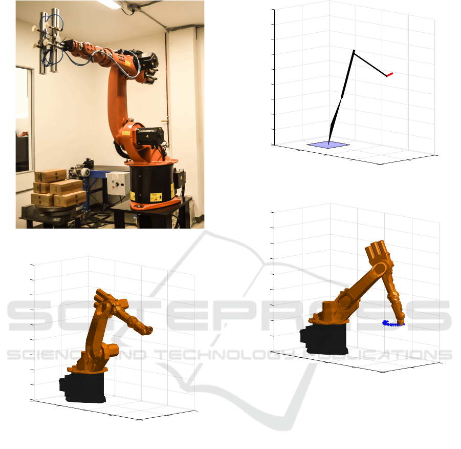
Figure 1: Commercial robotic arm KUKA KR6.
500
Y (mm)
0
-500
1500
1000
X (mm)
500
0
1000
1200
1400
1600
1800
0
200
400
600
800
-500
Z (mm)
Figure 2: 3D simulation of the KUKA KR6.
2.1. The 3D model obtained is shown in Figure 2. The
quality of the shape and the details can be set when
the STL file is exported in a CAD environment such
as Solid Edge or Solid Works. Depending on the com-
putational power available, less details mean a faster
simulation.
A simplified model of the robot was created as
well, in order to optimize real-time tests. This model
is shown in Figure 3. Excepting the base of the robot,
each link consists only of two points. The plot, in-
side the programming environment used, facilitated
the creation of straight lines between the points. The
red line is the end-effector. Recall that the robot is in
the same spatial position in Figures 2 and 3.
A kinematic test was performed in order to debug
500
Y (mm)
0
-500
1500
1000
X (mm)
500
0
200
400
600
800
1600
1400
1200
1000
1800
0
-500
Z (mm)
Figure 3: Simplified simulation of the KUKA KR6.
500
Y (mm)
0
-500
1500
1000
X (mm)
500
0
0
200
400
600
800
1000
1200
1400
1600
1800
-500
Z (mm)
Figure 4: Circular path executed by the simulated robot.
and validate the kinematic models. The task was to
make the end-effector of the simulated robot to follow
smoothly a circular trajectory. As showed in Figure 4,
the simulation performed the task correctly. The com-
putational model of the robot was hence validated.
3.2 Biosignal Acquisition, Processing
and Control Algorithms
EMG has been widely used in physical rehabilitation
systems and in upper limb prosthetics. There are two
methods to obtain EMG signals: surface electromyo-
graphy (sEMG) and intramuscular electromyography
(iEMG). In the first, electrodes are respectively at-
tached to the user skin, and in the latter they are in-
serted through the skin (Mon and Al-Jumaily, 2013).
sEMG signals have been effectively used in pros-
theses control systems (Merletti and Parker, 2004).
Therefore, sEMG signals were used to test the pro-
BIOSIGNALS 2016 - 9th International Conference on Bio-inspired Systems and Signal Processing
82

posed methodology.
The sensors, sensor placement and signal process-
ing methods to acquire and record sEMG signals were
based on some of the recommendations of the SE-
NIAM project (The Seniam Project, ). According to
ISEK Standards for Reporting EMG Data (Merletti,
1999) the characteristics of the procedure are shown:
The raw signal was detected using three pairs of
10-mm commercial, disposable and adhesive gel sur-
face electrodes placed in different parts of the forearm
of a healthy 25-year-old subject, along with a refer-
ence electrode located at the elbow. The electrodes
had a disc shape, an area of 3.48 sq cm, and were
made in silver-chloride. They were placed with a
inter-electrode distance of approximately 2 cm (center
point to center point) at the following muscles in order
to detect flexion and pronation (Florimond, 2010):
• Biceps brachii, detecting activation when the el-
bow joint was flexed.
• Brachioradialis, detecting activation when the
wrist pronation occured.
• Flexor carpi radialis, detecting activation when
the wrist joint was flexed.
The electrodes were placed in parallel to the mus-
cle fiber direction using the dominant middle portion
of the muscle belly for best selectivity and avoiding
the region of motor points. The signal was acquired
using an 8 channel low-cost sEMG signal acquisition
device designed and developed in our research labs.
The device has a differential configuration, an input
impedance of 10 kΩ, a signal-to-noise ratio (SNR)
of 112 dB and it was configured with a gain of 12.
The biosignal was sampled at 1 kHz. The low-cost
sEMG signal acquisition device transmitted the signal
through a serial port to a PC, and the programming en-
vironment used, recorded or captured in real-time all
three differential channels. The signals were obtained
one at the time, and they were normalized to the range
of (-1, 1).
Subsequently, the signal was rectified with Root
Mean Square (RMS) and it was converted into an am-
plitude envelope as presented in the literature (Mon
and Al-Jumaily, 2013). The RMS was calculated one
value at the time using the equation
RMS
emg
(n) =
s
1
n
∗
n
∑
s=1
sEMG(s)
2
, (1)
where sEMG(s) represents the amplitude estimation
(Ruiz et al., 2009) of the signal in the sth sample and
n is the total number of samples in a window from
the vector of the signal. The window used was 0.01
seconds, meaning each window had 10 samples. The
signal was not filtered again in the computational soft-
ware, but the RMS curve was normalized in the range
of (0, 1) so it could be useful in the procedure de-
scribed below.
The Normalized RMS curve of the sEMG was the
input of the kinematic analysis, in order to move the
model of the robot when the subject intended to move
his arm. From this resulting signal, labeled as input,
it was calculated the value of the position of the ma-
nipulator’s joints by means of a linear transformation.
In order to achieve this, each of the muscles, and cor-
respondent movements, were related to three joints of
the kinematic model of the KUKA KR6 serial manip-
ulator.
In order to test the proposed methodology, a sim-
plified EMG-based assistive control algorithm was
implemented. The mathematical relation was defined
so that the robot would move whenever the muscle
was activated, and in a proportional way to the ampli-
tude of the sEMG signal. If the muscle was not acti-
vated, the robot would not move from its home posi-
tion. When there was a muscle activation, the model
would change its position in a proportional way. This
movement was done inside the robot position limits,
meaning (0) the home position and (1) a custom po-
sition close to the maximum angle of the joint with a
comfortable safety distance.
The direct kinematic analysis was then effectuated
and the movement of the robot was displayed in the
screen using the D-H parameters. It was established
that joints 1, 2 and 6 were going to be immobile in
the home position of the robot (0
◦
, −90
◦
and 0
◦
re-
spectively). This indicates that the kinematic model
of the robot was used with only three joints, meaning
a 3 degrees of freedom (3-DOF) manipulator.
For the elbow flexion, the normalized RMS of the
biceps brachii signal, labeled as input3, was associ-
ated to the joint three of the kinematic model. The
maximum and minimum angles for this joint were set
to 220
◦
and 180
◦
respectively, and the angle of the
the joint three
θ
3
= 220 − 40 × input3 (2)
was computed from the input signal. For the wrist
flexion, the normalized RMS of the flexor carpi radi-
alis signals, input5, the maximum angles were set to
0
◦
and −45
◦
, and the angle of the the joint five
θ
5
= −45 × input5 (3)
was computed from the input signal. By last, for the
wrist pronation, the normalized RMS of the brachio-
radialis signals, input4, the maximum angles were set
to 0
◦
and 90
◦
, and the angle of the the joint four
θ
4
= 90 × input4 (4)
A Simulation-based Methodology to Test and Assess Designs of Mechatronic Neural Interface Systems
83
was computed from the input signal. This means that,
if the amplitude envelope of each input was small or
null (0), each joint of the kinematic model was close
to the home position, and if the amplitude envelope of
each input was big or maximum (1), each joint of the
kinematic model was close the maximum angle. As
the tests were performed with only one signal and its
corresponding joint at the time, the other two joints
were set at an arbitrary position.
3.3 Testing using Pre-recorded Signals
sEMG signals were recorded from the subject during
three trials of 20 seconds using the procedures pre-
sented in section 3.2. On each trial the subject was
told to perform movements in order to detect activa-
tion of each of the three muscles described. On the
first trial, he was told to flex his elbow two times. On
the second trial, he was told to pronate his wrist four
times. And on the third trial, he was told to flex his
wrist three times. Muscle activation was measurable
when these movements happened.
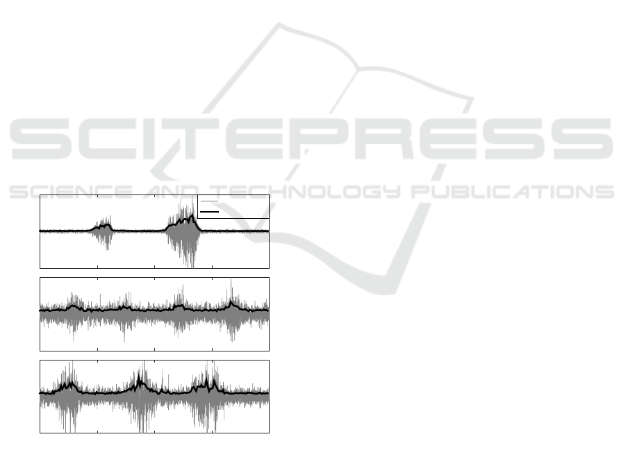
The sEMG signals obtained from each muscle and
their RMS values are shown in Figure 5. It is impor-
tant to remark that the results in this Figure are shown
before the RMS value was normalized and introduced
in the kinematic model. In this figure, the activation
and deactivation of the biceps brachii are represented
by five letters.
-1
0
1
Biceps brachii
sEMG signal
RMS value
Normalized Voltage
-1
0
1
Brachioradialis
Time (s)
0 5 10 15 20
-1
0
1
Flexor carpi radialis
a
b
c
d
e
Figure 5: Biosignals recorded with the low-cost sEMG ac-
quisition device.
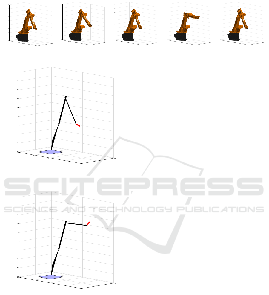
The output of the NISs is presented in Figure
6. It shows different positions of the robot dur-
ing the simulation of the NISs with the data pre-
viously recorded from the activation of the biceps
brachii. This signal was selected due to the fact
that presents the greater contrast between muscular
activation-deactivation. Also, it has different levels of
contractions producing different levels of signal am-
plitude, and for that reason is more didactic and visu-
ally representative in the simulation.
Each frame of the Figure 6 corresponds to a po-
sition in time. The first frame (a) corresponds to the
start of the trial, the second frame (b) to the first acti-
vation, which was really weak as can be seen in Fig-
ure 5 section (b), the third frame (c) corresponds to
the time between activations, the fourth frame (d) to
the second (and strongest) activation as can be seen in
Figure 5 section (d) and the fifth frame (e) to the time
after the activation. As these results were satisfactory,
the real-time tests were implemented.
3.4 Testing using Real-time Signals
In order to assess the feasibility of implementing the
designed NIS, the procedures shown in section 2.4
for the signal acquisition, processing, and control was
implemented. The signal processing and control al-
gorithms were executed in real-time detecting the ac-
tivation of the biceps brachii.
The sEMG acquisition device was connected to
the subject. It transmitted each sample through se-
rial port protocol at a baud rate of 115.200 through
an Universal Serial Bus (USB). The samples of the
raw signals were conducted to the signal processing
algorithm and then they were mapped in the control
algorithm.
The real-time experiments carried out on the
healthy subject involved a very simple algorithm to
detect the intended movement of the elbow, since the
purpose of this paper is the proposal of the method-
ology and not presenting a novel algorithm for the
detection of the intended movement through sEMG
signals. The detection of the elbow flexion was done
through a threshold established to the RMS envelope
of the biceps brachii signals. If the change in the
amplitude envelope exceeded the given treshold, the
joint 3 (also labeled input3) of the simplified kine-
matic model of robot was put at a maximum value.
Otherwise, it stayed at the minimum value. The tresh-
old used was 75% of the range of the RMS envelope
signal.
The test consisted on five activations of the muscle
separated approximately by two seconds. The simpli-
fied model of the robot moved correctly after each ac-
tivation. Figures 7 and 8 show the status of the robot
without and with an activation respectively.
BIOSIGNALS 2016 - 9th International Conference on Bio-inspired Systems and Signal Processing
84
500
Y (mm)
0
-500
1500
1000
X (mm)
500
0
1000
1200
1400
1600
1800
400
0
600
200
800
-500
Z (mm)
500
Y (mm)
0
-500
1500
1000
X (mm)
500
0
0
400
600
1600
200
1400
1800
1200
1000
800
-500
Z (mm)
500
Y (mm)
0
-500
1500
1000
X (mm)
500
0
200
0
400
1000
1200
1600
600
1800
800
1400
-500
Z (mm)
500
Y (mm)
0
-500
1500
1000
X (mm)
500
0
800
600
400
200
0
1800
1600
1200
1000
1400
-500
Z (mm)
500
Y (mm)
0
-500
1500
1000
X (mm)
500
0
1600
1800
0
200
400
600
800
1000
1200
1400
-500
Z (mm)
a
b
c
d
e
Figure 6: Movement using prerecorded signals.
500
Y (mm)
0
-500
1500
1000
X (mm)
500
0
200
400
600
800
1600
1400
1200
1000
1800
0
-500
Z (mm)
Figure 7: Simplified 3D model during the real-time experi-
ment with the elbow extended.
500
Y (mm)
0
-500
1500
1000
X (mm)
500
0
200
400
600
800
1600
1400
1200
1000
1800
0
-500
Z (mm)
Figure 8: Simplified 3D model during the real-time experi-
ment with the elbow flexed.
3.5 Discussion
After the tests developed in Subsections 3.3 and 3.4,
it can be stated that the simulation of the robot can be
successfully implemented and controlled by means of
a biosignal. The tests yielded three tools useful for
future projects:
The first one is the kinematic simulation of the
robotic arm KUKA KR6. This tool gives the re-
searcher the ability to recreate the movement of the
robot without interacting directly with a real device,
and its performance is suitable compared to the real
movement of the KUKA KR6. Additionally, it en-
ables the inclusion of accessories or more detailed
characteristics using the same instructions presented
in Section 2. For instance, if there is any change in
the design of the robot, it is only necessary to update
its D-H parameters and CAD model. Furthermore, as
the researcher checks the movement of the robot in the
screen, the tool enables the test and assessment of tra-
jectories of the different actuators and end-effectors
of the robot.
The second useful tool is the simplified model. It
may be useful to check the kinematic behavior of the
links of the robot’s mechanism, while enabling real-
time analysis.
A third and last tool is the sEMG acquisition and
processing system, which completes the Neural In-
terface System. sEMG signals are particularly (but
not exclusively) useful in the field of prosthetics, as
they can be measurable on the residual muscles of
amputees, allowing the patient to control a prosthetic
device.
It is important to note that the amplitude of the ac-
quired signals shown in Figure 5 is different, depend-
ing on some anatomic and physiologic characteristics
of muscle and the force applied in the movement. For
the case of the KUKA KR6, which is a serial robot
with a similar structure to a human arm, the correla-
tion with the human movement was straightforward.
For instance, the movement produced by the flexion
of the elbow, as a result of biceps brachii activation,
was visualized in the joint 3 of the robot.
We highlight that this paper does not present re-
sults with a real-life robot, only with a computational
model. Future works include a realistic test with the
industrial serial robot KUKA KR6 and, subsequently
with a mechatronic device that our laboratory is de-
veloping for a specific application in rehabilitation.
In that way we will be able to compare the results of
the robot movement presented in the simulation ap-
plying our methodology and the results with the real-
life neural interface system. Moreover, this test with
a real-life robot and a real-life neural interface system
A Simulation-based Methodology to Test and Assess Designs of Mechatronic Neural Interface Systems
85

will enable to develop a comparative evaluation with
other approaches.
4 CONCLUSION
The proposed methodology can be implemented in
the design stage of a NIS that involve a robotic de-
vice, since it can influence important decisions before
building the robotic system. Taking these decisions
before manufacturing processes may signify an eco-
nomical benefit for the designer.
In this work, the methodology was tested using
a KUKA KR6 robot. However, any serial robotic
device can be used. It is possible to implement the
methodology with robots that help people, such as
exoskeletons or upper limb prostheses. The only re-
quirement is to have their CAD files, which is usual
in the design process of any machine nowadays, and
convert them to STL format. Although sEMG sig-
nals were used in the presented experiments, EEG,
ECG, EOG and even electrocorticogram (ECoG) sig-
nals may be used as well as an input for the NIS. It is
recommended to follow the proper protocol to acquire
the signals.
In this paper a basic control algorithm was used to
map the angles from human joints to robot joints. It is
possible to include in the simulations more advanced
control algorithms according to the capabilities of the
real robot. Some of these algorithms may include dy-
namic analysis. Therefore, an interesting follow up
for the project is the development of force models in-
side the methodology.
Finally, we also propose that the presented
methodology has a potential use in the field of
biofeedback for musculoeskeletal and neurologic re-
habilitation, since the movement of the robot is an in-
dicator of muscular activation in real-time tests. Nev-
ertheless, in order to assess this proposition clinical
tests have to be carried out.
ACKNOWLEDGEMENTS
The authors would like to thank Cristian D. Mart
´
ınez
for the design and development of a Low-Cost sEMG
signal acquisition device.
REFERENCES
Asghari Oskoei, M. and Hu, H. (2007). Myoelectric control
systems-A survey. Biomedical Signal Processing and
Control, 2(4):275–294.
Corke, P. (2011). Robot Arm Kinematics. In Robotics, Vi-
sion and Control: Fundamental Algorithms in MAT-
LAB (Springer Tracts in Advanced Robotics), chap-
ter 7, pages 137–170. Springer.
Corke, P. I. (2007). A simple and systematic approach to as-
signing Denavit-Hartenberg parameters. IEEE Trans-
actions on Robotics, 23(3):590–594.
Correa, J. C., Ram
´
ırez, J. A., Taborda, E. A., Cock, J. A.,
G
´
omez, M. A., and Escobar, G. A. (2010). Imple-
mentation of a Laboratory for the Study of Robot Ma-
nipulators. In Proceedings of the ASME 2010 Inter-
national Mechanical Engineering Congress & Expo-
sition, pages 23–30.
Crane, C. D. and Duffy, J. (1998). Kinematic Analysis of
Robot Manipulators. Cambridge University Press.
Delis, A. L., Carvalho, J. L. a. J., and Rocha, A. F. (2006).
Myoelectric Knee Angle Estimation Algorithms for
Control of Active Transfemoral Leg Prostheses. Self
Organizing Maps - Applications and Novel Algorithm
Design, (1977):401–424.
Eurostat (2014). Disability statistics - prevalence and de-
mographics.
Florimond, V. (2010). Basics of Surface Electromyography
Applied to Physical Rehabilitation and. 1(March):1–
50.
Fu, K. S., Gonzalez, R. C., and Lee, C. S. (1987). Robotics:
control, sensing, vision and intelligence. McGraw-
Hill.
Garc
´
ıa Quiroz, F., Villa Moreno, A., and Casta
˜
no Jaramillo,
P. (2007). Interfaces neuronales y sistemas m
´
aquina-
cerebro: fundamentos y aplicaciones. Revisi
´
on. Re-
vista Ingenier
´
ıa Biom
´
edica, (1):14–22.
Hatsopoulos, N. and Donoghue, J. (2009). The science
of neural interface systems. Annual review of neuro-
science, 32:249–266.
Hon Wah, W. (1999). Introduction to STL format.
Kiguchi, K., Tanaka, T., and Fukuda, T. (2004). Neuro-
fuzzy control of a robotic exoskeleton with EMG
signals. IEEE Transactions on Fuzzy Systems,
12(4):481–490.
Kyrylova, A., Desplenter, T., Escoto, A., Chinchalkar, S.,
and Trejos, A. L. (2014). Simplified EMG-driven
Model for Active-Assisted Therapy. In IROS 2014
Workshop on Rehabilitation and Assistive Robotics:
Bridging the Gap Between Clinicians and Roboticists,
page 6.
Lasso, I. L., Masso, M., and Vivas, O. A. (2010). Ex-
oesqueleto para reeducaci
´
on muscular en pacientes
con IMOC tipo diplej
´
ıa esp
´
astica moderada. pages
1–88.
Lenzi, T., De Rossi, S. M. M., Vitiello, N., and Carrozza,
M. C. (2012). Intention-based EMG control for pow-
ered exoskeletons. IEEE Transactions on Biomedical
Engineering, 59(8):2180–2190.
Lucas, M. F., Gaufriau, A., Pascual, S., Doncarli, C., and
Farina, D. (2008). Multi-channel surface EMG clas-
sification using support vector machines and signal-
based wavelet optimization. Biomedical Signal Pro-
cessing and Control, 3(2):169–174.
Merletti, R. (1999). Standards for reporting EMG data.
BIOSIGNALS 2016 - 9th International Conference on Bio-inspired Systems and Signal Processing
86

Merletti, R. and Parker, P. A. (2004). Electromyography:
Physiology, Engineering, and Non-Invasive Applica-
tions. John Wiley & Sons.
Mon, Y. and Al-Jumaily, A. (2013). Estimation of Up-
per Limb Joint Angle Using Surface EMG Signal.
International Journal of Advanced Robotic Systems,
page 1.
National Limb Loss Center Information (2008). Amputa-
tion statistics by cause. Limb loss in the United States.
Pan, D., Gao, F., Miao, Y., and Cao, R. (2015). Co-
simulation research of a novel exoskeleton-human
robot system on humanoid gaits with fuzzy-PID/PID
algorithms. Advances in Engineering Software,
79:36–46.
Revilla, L. M., Delis, A. L., and Olaya, A. F. R. (2013).
Evaluation of the Hilbert-Huang Transform for my-
oelectric pattern classification: Towards a method to
detect movement intention. Pan American Health
Care Exchanges, PAHCE, pages 1–6.
Ruiz, A. F., Rocon, E., and Forner-Cordero, A. (2009).
Exoskeleton-based robotic platform applied in biome-
chanical modelling of the human upper limb. Applied
Bionics and Biomechanics, 6(2):205–216.
Schultz, A. E. and Kuiken, T. A. (2011). Neural interfaces
for control of upper limb prostheses: the state of the
art and future possibilities. PM & R : the journal of
injury, function, and rehabilitation, 3(1):55–67.
The Seniam Project. SENIAM. http://www.seniam.org.
Tsai, L.-W. (1999). Robot analysis: the mechanics of serial
and parallel manipulators. John Wiley & Sons.
Wojtczak, P., Amaral, T. G., Dias, O. P., Wolczowski, A.,
and Kurzynski, M. (2009). Hand movement recogni-
tion based on biosignal analysis. Engineering Appli-
cations of Artificial Intelligence, 22(4-5):608–615.
World Health Organization (2011). World Report on Dis-
ability.
Yepes, J. C., Yepes, J. J., Mart
´
ınez, J. R., and P
´
erez, V. Z.
(2013). Implementation of an Android based teleoper-
ation application for Controlling a KUKA-KR6 robot
by using sensor fusion. Health Care Exchanges.
Ziegler-Graham, K., MacKenzie, E. J., Ephraim, P. L.,
Travison, T. G., and Brookmeyer, R. (2008). Estimat-
ing the Prevalence of Limb Loss in the United States:
2005 to 2050. Archives of Physical Medicine and Re-
habilitation, 89(3):422–429.
A Simulation-based Methodology to Test and Assess Designs of Mechatronic Neural Interface Systems
87
