
mNetra: A Fundoscopy based Optometer
Vijay Kumar
1
and Kolin Paul
2
1
Amarnath Khosla School of Information Technology, Indian Institute of Technology Delhi, New Delhi, India
2
Department of Computer Science and Engineering, Indian Institute of Technology Delhi, New Delhi, India
Keywords:
Mobile Phone, Ophthalmoscope, Funduscopy, Refractometer, Optometer, Visual Acuity, Refractive Error,
Fundus Image, Mobile Phone, Android.
Abstract:
Untreated refractive error in the eye is one of the leading causes of preventable blindness. The devices nec-
essary for this is expensive and often requires skilled technicians to operate. In this paper, a common off the
shelf ophthalmoscope has been modified and integrated with a smart phone to build an affordable optometer.
The device has been tested on a statistically significant population with refractive error range from −8.00D to
+3.50D. We found a reasonably good correlation with other prevalent methods of measuring refractive error
in the eye.
1 INTRODUCTION
Worldwide more than 285 million people suffer from
some form of visual impairment (WHO.int, 2014).
Out of this 90% person live in developing countries.
The WHO has published a report in 2010 that, the
leading causes of visual impairment throughout the
world are the untreated refractive error (43%), unop-
erated cataract (33%) and glaucoma (2%)(WHO.int,
2014). There are an estimated 19 million children are
visually impaired and out of these, 12 million chil-
dren are suffering from refractive errors, a condition
that could be easily diagnosed and corrected (Pascol-
ini and Mariotti, 2011). Worldwide myopia is lead-
ing cause of low vision in young children, especially
school going children (Resnikoff et al., 2008; Sax-
ena et al., 2015). That can hinder education, produc-
tivity, personality development and career opportuni-
ties. The impact of blindness due to refractive error
(myopia) in young age is very high as compared to
cataracts or glaucoma in old age because it affects the
person for a longer span of time starting from child-
hood. It also places a greater socioeconomic burden
for developing countries like India.
The human eye is a sophisticated and complex
imaging system which is capable of dynamically
adjusting its focal power for wide ranges of dis-
tance. The eye’s refractive power is maintained by the
air-cornea interface (corneal shape dependent fixed
power) and crystalline lens (provides an adjustable
extra power to the eye). Common refractive errors
found in the eye (in Fig.1) are due to imperfections
in eyeball shape, lens and cornea. The Myopic eye
shown in Fig.1(b), has an enlarged axial length (the
length from the posterior corneal surface to the retina)
or an increase in the refractive power of the eye lens
and focuses parallel rays to a point in front of the
retina rather than on it. In contrast, the Hyperopic
shown in Fig.1(c), has a short eye or insufficiently
curved cornea and focuses parallel rays at a point be-
hind the retina. A Healthy eye (In Fig.1(a)) on the
other hand, can focus parallel rays to a single point on
the retina.
The refractive disorder is commonly treated us-
ing appropriate corrective lenses such as eyeglasses
or contact lens. For this to be possible a periodic but
comprehensive examination of the eye is mandated
especially in school and primary health care centers.
To do this, three diagnostic methods are primarily
used to evaluate the refractive error.
• Subjective Methods: Its screening result relies
upon the response and reaction of a patient, e.g.
patient’s judgment of sharpness or blurriness of a
test object (Snellen eye chart).
• Objective Methods: This method doesn’t depend
on the feedback from the patient. The optical in-
strument that can find out the refractive error au-
tomatically, e.g. refractometer and optometer.
• Hybrid Methods: Currently, this is the most
common way to determine refractive error to pre-
scribe corrective lens. It consists of two steps. An
objective method is used in the first step followed
by the subjective method to determine the accu-
Kumar, V. and Paul, K.
mNetra: A Fundoscopy based Optometer.
DOI: 10.5220/0005698500830092
In Proceedings of the 9th International Joint Conference on Biomedical Engineering Systems and Technologies (BIOSTEC 2016) - Volume 5: HEALTHINF, pages 83-92
ISBN: 978-989-758-170-0
Copyright
c
2016 by SCITEPRESS – Science and Technology Publications, Lda. All rights reserved
83
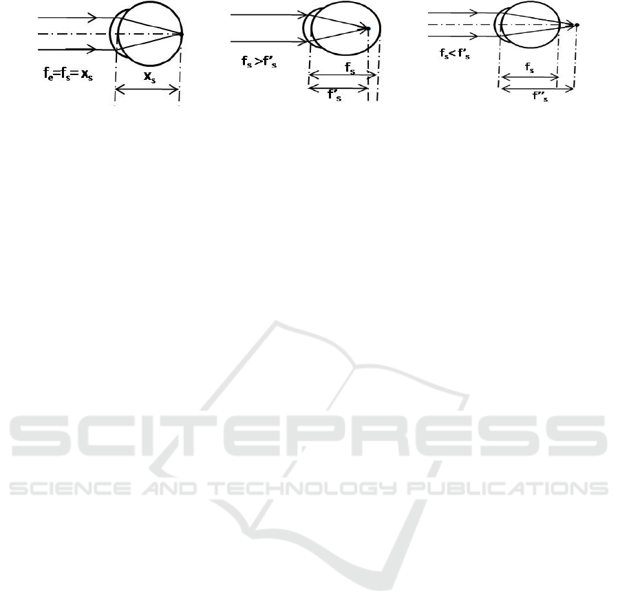
(a) Healthy eye (b) Myopia (c) Hyperopia
Figure 1: Common retinal refractive error in the human eye.
rate corrective lens.
For the above have a method of refractive error
screening ophthalmologists used optical technology
based diagnostic instruments such as auto refractome-
ter, focometer, retinoscopy, and wavefront analyzer
can be used for measuring the refractive power of the
human eye (Ko and Lee, 2006; Berger et al., 1993;
Dave, 2004) is bulky, expensive, sophisticated, highly
application specific and needs a trained technician to
operate these devices.
Recently, portable devices (smartphones and
tablets) have emerged as a versatile mobile computing
platform with high resolution display, which provides
us a new opportunity for mobile health (mHealth).
Paul et al. (Paul and Kumar, 2015) use the oph-
thalmoscope and mobile phone to develop an afford-
able fundus imaging based eye care device for glau-
coma screening. Peek Vision provides high qual-
ity tools for professional eye exams using a mobile
phone (PeekVision, 2015). It can be used to diagnose
cataracts, visual acuity and eyesight, colour and con-
trast of the eye. In (Pamplona et al., 2010; Cameracul-
ture.media.mit.edu, 2015), NETRA and CATRA pro-
vide affordable cell phone attachment that measure
the eye refractive power and cataracts information. It
creates an inverse Shack-Hartmann sensor based on
a ”high resolution programmable display and com-
bines inexpensive optical elements, interactive GUI,
and computational reconstruction”. Currently, Smart
Vision Labs have developed a smartphone based af-
fordable auto refraction technology based on Wave-
front aberrometry (Shack Hartmann) to measure the
refractive error of the eye (Zhou and Kassalow, 2010).
In this paper, we introduce a novel low cost, hand
held, portable, reliable, accurate and interactive in-
strument mNetra, based on view dependent display
to determine the refractive error in the human eye for
fast and accurate screening. The ophthalmoscope and
smart phone based device tries to get the best im-
age/video frame of the retinal scan after proper adjust-
ment of ophthalmoscope lens focusing wheel. This
paper presents,
• A methodology to do refraction of the eye for
screening using a mobile phone an ophthalmo-
scope.
• An Android based application has been devel-
oped, which allows collection of patient details
and perform the computation for refraction. A
generic Regression (R) model to demonstrate that
an off the shelf ophthalmoscope can be attached
to the mobile phone is also described in the paper.
We believe that our funduscopy based optometry
increase the usability and application of ophthalmo-
scope and mobile phone. It provides a suitable solu-
tion for affordable eye care in developing countries.
And this is particularly useful in prescribing correc-
tive lenses for patients who are unable to undergo a
subjective refraction that requires a judgment and re-
sponse from the patient (e.g. a person with communi-
cation problems or severe intellectual disabilities).
2 mNetra
The mNetra is a monocular, funduscopy based hand-
held optometry which uses the principle of ophthal-
moscopy to measure refractive error. The optician
uses the manual rotary wheel to focus the image on
the retina. This concept has been explored to do same
automated refraction in the mNetra. We describe the
methodology in the following subsection.
The Mobile ophthalmoscope is an optoelectron-
ics handheld, an affordable lightweight instrument for
screening the interior structure of the eye, especially
the back part of the eye (fundus: which includes
the retina, optical disk, optical cup, blood vessel and
fovea etc.). This also supports computation and com-
munication needs for processing and sharing of med-
ical data. This optoelectronic device has been made
possible by integrating the smartphone and an oph-
thalmoscope.
The total optical power of a multiple lens system
is equal to the linear summation of individual lens
power. In Fig. 4(b), ophthalmoscopy based screening
system’s optical unit consist of the ophthalmoscope,
subject (patient) eye and a camera rather than ophthal-
moscope, subject eye and observer eye (in Fig. 4(a)).
This new multiple lens optical system is in equilib-
HEALTHINF 2016 - 9th International Conference on Health Informatics
84
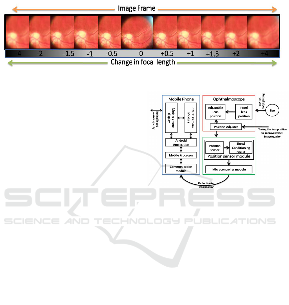
Figure 2: Basic concept of retinoscopic refractometer :In this figure, fundus image quality is detonated with increment or
decrement of focusing lens focus.
rium condition (total power is zero) for the healthy
eye with no refractive error. A small change in the
power (δP) of any lens in this system will disturb the
equilibrium of the whole optical system.To overcome
and nullify this problem, we should use the other lens
of opposite power (−δP) so it will again maintain the
equilibrium.
We use this concept to develop a funduscopy
based optometer using an ophthalmoscope and mo-
bile phone. This has been made possible by making
some changes in the basic ophthalmoscope and em-
bedding mobile phone. In Fig. 4(b) of the new opti-
cal system, the observer’s eye is replaced by CMOS
camera module (Mobile phone) and focusing lens can
be used to correct the ocular error i.e. due to sub-
ject/patient eye refractive alignment. The focusing
lens position is controlled by the ophthalmoscope fo-
cusing lens wheel (in Fig. 5(c)). In Fig. 2, we show
how the quality of the image frame depends on the
focal length of the focusing lens set with the focusing
wheel of the ophthalmoscope.
Mathematically, refractive error corrective power
(P) is the function of focusing lens position (x).
Where, x is the function of focusing wheel angle θ.
So that,
P = F(x) = F(g(θ)) = F(r × θ) (1)
Where, r is the radius of the focusing wheel. and in
another way it can be written as P =
1
f
s
and from the
equation 23, P ≡ P
s
.
2.1 Functional and Architectural
Overview
In this section, we outline the design of a mobile oph-
thalmoscope based optometer subjected to the con-
straints of Cost, Bulkiness, Portability and Adopt-
ability.The device is based on the Smartphone. This
has been made possible by embedding the Optical
(Ophthalmoscope and CMOS camera), Computing
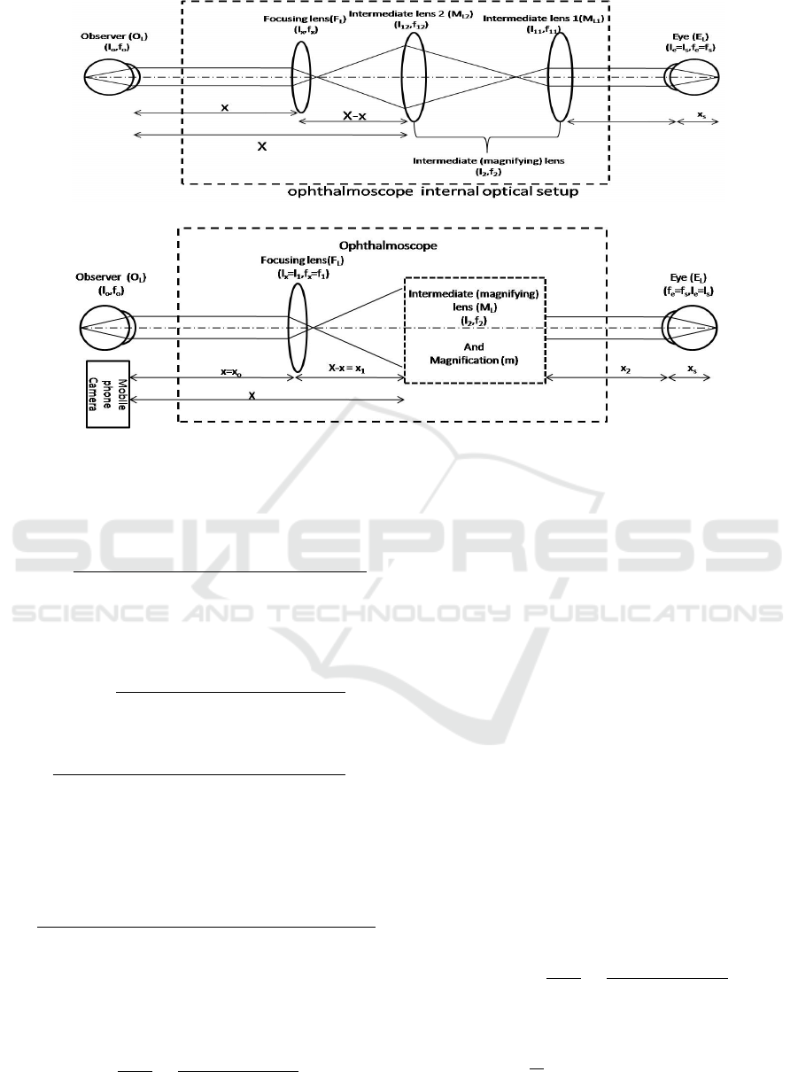
Figure 3: Working diagram of ophthalmoscope based hand
held refractometer.
(Mobile phone and Microcontroller), Sensor (poten-
tiometer based position sensor) functionality in a sin-
gle device. As illustrated in Fig. 3, the device consists
of different functional block which are described be-
low:
• Optical System: This block capture the magni-
fied fundus image with a CMOS camera –typical
CMOS in nature. The key innovation in the solu-
tion is to replace the eye of ophthalmologist by of
a smartphone camera based CMOS sensor to cap-
ture the image of patient’s fundus. We use a smart
phone of a high resolution (≥5MP) camera for the
same. We have also designed and build a custom
mobile phone holder Rapid Prototype (RP) model
to attach the Smartphone camera to the ophthal-
moscope.
• Computing Unit: This functional unit consists of
a smart phone processor and the microcontroller
for processing the mobile phone data (CMOS cap-
ture video/image) and controlling and processing
of focusing lens sensor output respectively. Mo-
bile phone centralized processing and control unit
is able to satisfy high compute power required
for image processing, result visualization and data
sharing that are part of the application software.
mNetra: A Fundoscopy based Optometer
85

• Sensory System: To measure the ophthalmo-
scope focusing lens position we used a sensor
module that will measure the current position of
focusing wheel. In Fig. 3, it consists of Position
sensor, Microcontroller and Bluetooth module
to share the current status of focusing wheel to the
mobile phone for further processing and represen-
tation.
2.2 The Mathematical Basis
Ophthalmoscopy based optometer’s optical setup and
working rays diagram are shown in Fig. 4. It consists
of the ophthalmoscope, subject eye and CMOS sen-
sor (mobile phone camera). In this optical setup, we
should consider the position of all lenses, i.e. magni-
fying lens (M
L
= {M
L1
,M
L2
}), subject eye (E
L
) and
CMOS sensor (O
L
) are fixed except focusing lens
(F
L
). The focusing lens is used to overcome and nul-
lify the refractive error of the subject eye lens so that
image properly focused on CMOS sensor. In this
section, we explain the mathematical relationship be-
tween focusing lens (F
L
) position (x) and subjective
eye power (P = 1/ f
e
).
For subject lens E
L
(l
s
, f
s
):
1
x
s
+
1
q
s
=
1
f
s
(2)
from the lens maker formula.
Similarly for lens M
L
(l
2
, f
2
):
1
x
0
2
+
1
q
2
=
1
f
2
(3)
where, x
0
2
= x
2
+ q
s
. Hence 3 becomes
1
x
2
+ q
s
+
1
q
2
=
1
f
2
(4)
Similarly for lens F
L
(l
1
, f
1
):
1
u
+
1
v
=
1
f
⇔
1
x
0
1
+
1
q
1
=
1
f
1
(5)
where, x
0
1
= X −x + q
2
. Hence 5 becomes,
1
(X − x + q
2
)
+
1
q
1
=
1
f
1
(6)
Similarly for lens O
L
(l
o
, f
o
):
1
u
+
1
v
=
1
f
⇔
1
x
0
0
+
1
q
0
=
1
f
o
(7)
where, x
0
o
= (x = x
o
) + q
1
. Hence 7 becomes,
1
x + q
1
+
1
q
o
=
1
f
o
(8)
Rearranging 2 we get
q
s
=
f
s
x
s
x
s
− f
s
(9)
which implies q
s
is a function of f
s
.
q
s
= F( f
s
) (10)
Similarly
q
2
=
f
2
x
0
2
x
0
2
− f
2
=
f
2
(x
2
+ q
s
)
(x
2
+ q
s
) − f
2
(11)
⇒ q
2
= F(q
s
) = F(F( f
s
)) ⇒ q
2
= G( f
s
) (12)
where,
G = F(F) (13)
From 5 and 6
q
1
=
f
1
x
0
1
x
0
1
− f
1
=
f
1
(X − x + q
2
)
(X − x + q
2
) − f
1
(14)
q
1
= H(G) =
f
1
(X − x + G)
(X − x + G) − f
1
(15)
Also from 7 and 8 :
q
o
=
f
o
x
0
o
x
0
o
− f
o
=
f
o
(x + q
1
)
x + q
1
− f
o
(16)
Similarly
q
o
=
f
o
(x + H(G))
x + H(G) − f
o
(17)
q
o
= I(H,x) (18)
and q
o
is constant. and from 17
x =
f
o
H(G)− q
o
H(G)+ f
o
q
o
(q
o
− f
o
)
(19)
Assuming the position and focal length of all the
lenses are fixed except for the focussing lens F
L
. We
obtain from 9 and 11
q
2
=
f
2
(x
2
+
f
s
x
s
x
s
− f
s
)
(x
2
+
f
s
x
s
x
s
− f
s
) − f
2
⇒ q
2
=
f
2
(x
2
(x
s
− f
s
) + f
s
x
s
)
(x
2
(x
s
− f
s
) + f
s
x
s
) − f
2
(x
s
− f
s
)
(20)
Using equations 14 and 16
⇒ q
o
=
f
o
(x + q
1
)
x + q
1
− f
o
=
f
o
(x + (
f
1
(X−x+q
2
)
(X−x+q
2
)− f
1
))
x + (
f
1
(X−x+q
2
)
(X−x+q
2
)− f
1
) − f
o
HEALTHINF 2016 - 9th International Conference on Health Informatics
86
(a) Optical system of ophthalmoscope used for funduscopy
(b) Optical system of mNetra
Figure 4: Optical rays diagram for (a) ophthalmoscope and (b) mNetra : Retinal image formation on observer eye/CMOS
sensor in ophthalmoscope from the rays coming from the subject eye.
⇒ q
2
=
q
o
(Xx − x
2
− 2 f
1
x + f
o
x) + q
o
( f
1
X − f
o
X
− f
o
f
1
) − f
o
f
1
X − X x f
o
+ f
o
x
2
− 2 f
1
f
o
x
(−q
o
x − q
o
( f
1
− f
o
) − f
o
x + f
1
f
o
)
(21)
Combining equation 12 and 20,
⇒
f
2
(x
2
(x
s
− f
s
) + f
s
x
s
)
(x
2
(x
s
− f
s
) + f
s
x
s
) − f
2
(x
s
− f
s
)
=
q
o
(Xx − x
2
− 2 f
1
x + f
o
x) + q
o
( f
1
X − f
o
X
− f
o
f
1
) − f
o
f
1
X − X x f
o
+ f
o
x
2
− 2 f
1
f
o
x
(−q
o
x − q
o
( f
1
− f
o
) − f
o
x + f
1
f
o
)
Rearranging the above expression and we get,
f
s
=
(−q
o
x − q
o
( f
1
− f
o
) − f
o
x + f
1
f
o
)( f
2
x
2
+ f
2
x
s
)
−(q
o
(Xx − x
2
− 2 f
1
x + f
o
x) + q
o
( f
1
X − f
o
X − f
o
f
1
)
− f
o
f
1
X − Xx f
o
+ f
o
x
2
− 2 f
1
f
o
x)(x
2
x
s
+ f
2
x
s
)
f
2
(−q
o
x − q
o
( f
1
− f
o
) − f
o
x + f
1
f
o
) − (q
o
(Xx
−x
2
− 2 f
1
x f
o
f
1
) + f
o
x) + q
o
( f
1
X − f
o
X − f
o
f
1
)
− f
o
f
1
X − Xx f
o
+ f
o
x
2
− 2 f
1
f
o
x)(x
s
− x
2
+ f
2
)
(22)
We can write, 22 as a
f
s
=
N(x)
D(x)
=
N
2
x
2
+ N
1
x + N
o
D
2
x
2
+ D
1
x + D
o
(23)
where,
N
2
= (q
o
− f
o
)(x
2
x
x
+ f
2
x
s
)
N
1
= (−q
o
− f
o
)( f
2
x
2
+ f
2
x
s
) − (x
2
x
s
+ f
2
x
s
)
(q
o
X − 2q
o
f
1
+ q
o
f
o
− X f
o
− 2 f
1
f
o
)
N
o
= ( f
1
f
o
− q
o
( f
1
− f
o
))( f
2
x
2
+ f
2
x
s
) + ( f
o
f
1
X
−q
o
( f
1
X − f
o
X − f
o
f
1
))(x
2
x
s
+ f
2
x
s
)
D
2
= (q
o
− f
o
)(x
s
− x
2
+ f
2
) f
2
D
1
= −q
o
f
2
− f
2
f
o
− q
o
X + (2q
o
f
1
− q
o
f
o
+X f
o
+ 2 f
1
f
o
)(x
s
− x
2
+ f
2
)
D
o
= −q
o
f
2
( f
1
− f
o
) + f
2
f
1
f
o
+ ( f
o
f
1
X
−q
o
( f
1
X − f
o
X − f
o
f
1
))(x
s
− x
2
+ f
2
)
Now from the 22 the lens power P
s
is ,
P
s
= 1/ f
s
=
D(x)
N(x)
=
D
2
x
2
+ D
1
x + D
o
N
2
x
2
+ N
1
x + N
o
(24)
From the above mathematical expression, we see
that the patient eye refractive power (P
s
is function
of x. and P
s
=
1
f
s
. We used this concept and mathe-
matical relation to develop a mobile ophthalmoscope
mNetra: A Fundoscopy based Optometer
87
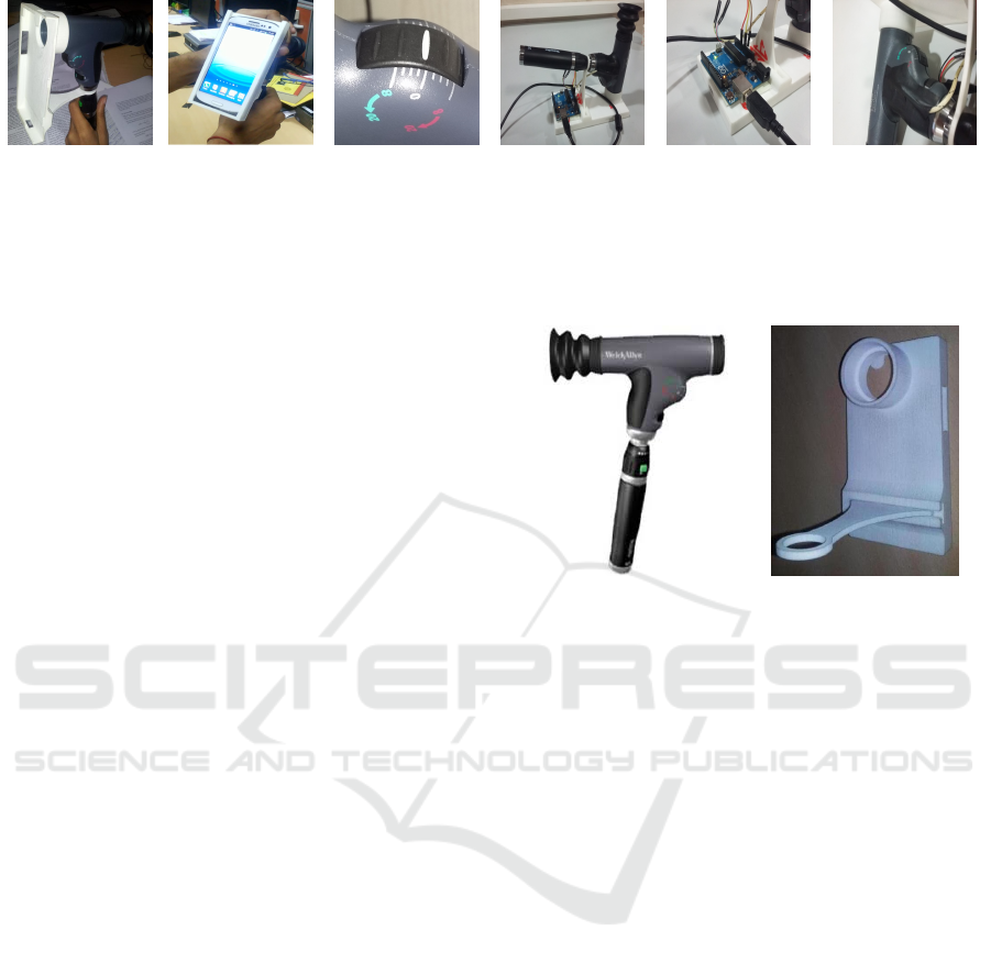
(a) (b) (c) (d) (e) (f)
Figure 5: Ophthalmoscope based funduscope: (a) Mobile phone holder attached with ophthalmoscope (b) Mobile phone is
attached with ophthalmoscope using this holder and (c) Focusing wheel of ophthalmoscope: Its is used to focussing the image
onto the mobile phone camera. In funduscopy based refractometer used this wheel’s rotation to find out refractive error of the
eye/lens. Position Sensor module (d)to (f):Position sensor interfaced with ophthalmoscopy based refractive error screening
device for communication with Android application using blue tooth.
based affordable handheld refractive error screening
device.
We describe the functional aspects of the design
in the next section.
3 DETAIL DESIGN
In this section, we outline the design of funduscopy
based optometer using the handheld ophthalmoscope,
mobile phone and its application software. This has
been made possible by integrating the optical (imag-
ing unit: ophthalmoscope and mobile phone camera),
computing (micro-controller and mobile phone) and
sensor (position sensor) unit in a single device shown
in Fig. 5. The three major components are described
below.
3.1 Ophthalmoscope
The ophthalmoscope is an optical instrument for ex-
amining the interior structure of the eye, especially
the back part of the eye (fundus), which includes
the retina, optical disk, optical cup, blood vessel and
fovea etc. An Ophthalmoscope is of two kinds, direct
and indirect. We use the PanOptic ophthalmoscope
(Fig. 6(a)) which is very similar to the traditional oph-
thalmoscope (Welchallyn.com, 2015).
3.2 Mobile Phone
For image capturing, image processing and data shar-
ing, we need a system that has the capability to per-
form all these jobs. We use a Smart-phone, which
has these features along with communication and data
sharing capability. It full fills the requirement of (a)
High resolution CMOS camera (b) Centralised Con-
trol System to synchronise and control all process (c)
High computation capability to perform image pro-
cessing (d) high resolution display and (e) sharing re-
(a) (b)
Figure 6: (a) Pan-Optic Ophthalmoscope and (b) Mobile
phone holder rapid prototype model.
sult and data with remote users. We have used an An-
droid based Samsung Galaxy S-3 smartphone.
Mobile Phone Holder
The smartphone camera is able to capture fundus im-
age only when if it is properly interfaced with a hand-
held portable ophthalmoscope. In this device, the
physician’s eye (Fig. 4(b)) is replaced by Smartphone
Camera. For that a special phone holder as shown in
Fig. 6(b) has been designed. The design of this was
done so that the functionality of the basic phone was
not impaired.
The material used in RP for building the case of
SLS. The mobile case, when integrated with the Oph-
thalmoscope, is shown in Fig. 5(b).
3.3 Rotary Detail or Sensor Module
In the Fig. 7, ophthalmoscope’s rotary wheel is used
to focus the retinal image on CMOS sensor camera.
This rotary wheel is connected to the focusing lens
such that it controls its position (x). It follows the re-
lation: x = r × θ where, r and θ are the radius and
rotational angle of the focusing wheel of an ophthal-
moscope.
To measure the precise position of the rotary
HEALTHINF 2016 - 9th International Conference on Health Informatics
88

Figure 7: Housing of the position sensor inside the oph-
thalmoscope to measure the lens position. The sensor will
measure the rotational movement (θ) of the focusing wheel.
wheel we have used a high precision position sensor
module. In Fig. 5 & Fig. 7, this module consists
of a potentiometer, a micro-controller (Arduino or
Intel Galileo Gen 2) board and a Bluetooth module
(RN42N) is used. This senses the current status of fo-
cusing lens position (x) as a function focusing wheel’s
angle (θ) and sends the processed data to the mobile
phone via Bluetooth. The sensor module uses embed-
ded software to control and communicate the wheels
rotational information and focusing lens data to the
mobile phone.
An Android application has been developed to
provide an interactive testing environment to the de-
vice. It consists of two sections, one is to display the
fundus scan (retinal scan ) and another one is to dis-
play the current status of focusing lens (refractive er-
ror value of the eye).
4 RESULTS
This section discusses the experiments conducted in
the laboratory and a hospital for the validation of our
new ophthalmoscope based funduscopy type optome-
ter. This has been done in two stages. In the first
stage, we have performed a lab based primary con-
cept validation (Fig. 8). Here we put different lenses
in front of mobile phone based fundus imaging de-
vice and then focus the image on the CMOS sensor
using the focusing wheel. This enables us to closely
relate the mNetra refractive power (P(x)) expression
24 with potentiometer reading. For this, experimen-
tal data and the result are shown in Table. 1. It is
clear that the ophthalmoscope focusing wheel read-
ing depends on the power of the lens in the test. In
the second stage, we have performed the testing and
validation with real (subjective) data (Patients) in the
(a) (b)
Figure 8: mNetra Concept validation test: (a) Optical setup
of the laboratory and (b) the optical lens.
hospital. For this experiment, we chose volunteers in
the age group 20-45 year. The volunteers were se-
lected randomly to cover a range of refractive error
power.
4.1 Test Methodology
For the above two scenarios, we followed a standard
predefined test procedure. In the first stage, we used
an optical eye model (Fig. 8(a)) in which variable lens
(+3.5D to -6.0D) (Fig. 8(b)) and the object was placed
at a distance of 1 meter. And for device validation,
we estimate it’s lens power (shown in Table. 1) using
our funduscopy based method. With the second stage
of subjects, we compared our result with the hybrid
method of refractive error screening. The data were
collected using this protocol.
1. The lighting in the room is dim/dark: This ensures
that person pupil’s is dilated to the maximum.
2. The person is sitting in the rest condition.
3. To minimize the eye lens power measurement er-
ror, observer asks the patient to focus his/her eye
on distinct object and infinity. This helps in accu-
rately performing the refraction.
4. The observer/technician measuring the blur in the
image using the focusing wheel.
5. Take the reading of focusing wheel when the fun-
dus image quality is best as compared to previous
Table 1: Experimental results: Lens power measurement
using mNetra.
S.No Lens Power (D) mNetra reading
01. +3.5 2.0
02. +2.0 1.25
03. +1.0 0.75
04. 0.0 0.25
05. -1.0 0.0
06. -2.50 -0.25
07. -3.5 -1.0
08. -4.0 -1.75
09. -5.25 -2.25
10. -6.0 -2.75
mNetra: A Fundoscopy based Optometer
89
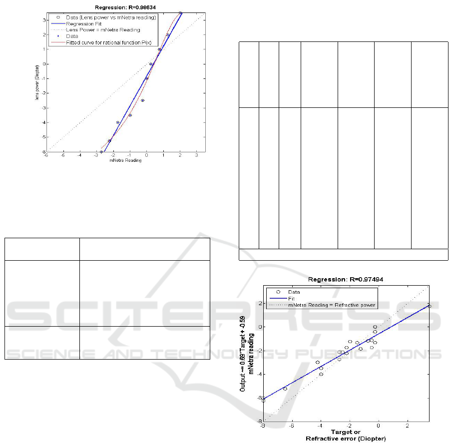
Figure 9: Regression and Curve fitting plot of the actual
lens power vs mNetra measured power. R value for mNetra
readout is (0.98634).
Table 2: Curve fitting parameter: Lens power P(x) mea-
surement using mNetra.
General model
Rational model :
P(x)or f (x) = (p1 ∗ x
2
+ p2 ∗
x + p3)/(x
2
+ q1 ∗ x +q2)
Coefficients
(with
p1 = −9.967(−54.24, 34.3)
95% confidence p2 = 42.38(−11.15, 95.91)
bounds) p3 = −16.33(−40.82, 8.148)
q1 = −5.104(−27.09, 16.88)
q2 = 14.44(−9.752, 38.64)
Goodness of fit SSE: 1.276, R-square: 0.9861,
Adjusted R-square: 0.9749,
RMSE: 0.5052
all images shown on mobile screen.
6. Repeat 3-5 again to take a retinal scan of another
eye also.
4.2 Data Analysis
The data that is collected is analyzed for accuracy and
efficiency in use for practical settings. The first set of
trials gives the test data for obtaining the correlation
between the potentiometer based readout and the ac-
tual power of the subject lens.
Experiments for the lens of power range +3.5D to
-6.0 were performed and the data are shown in Table
1. The data is subject to a curve fit as shown in Fig. 9.
For this regression analysis, we get the regression
coefficient 0.98634 and curve fitting result is shown
in table 2. This shows that the potentiometer readout
is able to track closely the actual power of the subject
lens.
Table 3: Subjective trial of device: Refractive power of eye
estimated using hybrid method and using funduscopy based
device.
S.
No
Sex Age left
eye
power
(D)
left
eye
mNe-
tra
read-
ing
right
eye
power
(D)
right
eye
mNe-
tra
read-
ing
1 F 35 -1.5 -1.33 -0.75 -1.17
2 F 36 -0.25 -0.42 -0.25 -1.33
3 M 24 -2.25 NA -1.25 NA
4 M 26 -0.5 -1.125 -0.5 -1.75
5 M 25 -1.25 -1.875 -2.25 -6.25*
6 M 24 -2.25 -2.25 -2.0 -1.25
7 M 23 -0.25 0.0 +3.5 +1.75
8 M 24 -4.0 -3.5 -4.0 -4.0
9 M 23 -8.0 -6.0 -8.0 -6.25
10 F 24 -6.5 -5.25 -6.5 NA
11 M 23 -2.25 -1.75 -2.75 -2.125
13 F 27 -4.25 - 3.0 -4.50 NA
14 M 20 -2.75 -2.75 -2.50 -2.125
*/NA Data sets are not considered for analysis
Figure 10: Regression analysis of eye lens power using an
ophthalmoscope and Regression coefficient R = 0.9749.
Subjective
In the second stage, data are collected from volunteers
using our device and hybrid method for refractive er-
ror estimation (shown in table.3) is used.
Validation
For the validation, we compared mNetra reading (D
m
)
with eye refractive power (i.e. true power D
T
) shown
in table 5. For this, we compute the estimated power
using the mNetra power Equation 24 and then find out
the error power (D
e
= D
T
−D
P
). We got the Standard
HEALTHINF 2016 - 9th International Conference on Health Informatics
90

Figure 11: In this graph refractive power (D) vs mNetra
potentiometer reading’s relation fitted with rational function
f (x) = P(x).
Table 4: Curve fitting parameter’s value for a rational model
of expression 24 with subjective trial.
General
model
Rational
model
P(x)or f (x) = (p1 ∗ x
2
+ p2 ∗ x +
p3)/(x
2
+ q1 ∗ x +q2)
Coefficients p1 = −2.393e + 04(−9.676e +
07,9.672e + 07)
(with 95% p2 = 5.816e + 04(−1.291e +
08,1.292e + 08)
confidence p3 = −3.215e + 04(−4.932e +
07,4.925e + 07)
bounds) q1 = −3.472e + 04(−1.404e +
08,1.403e + 08)
q2 = 5.469e + 04(−8.377e +
07,8.388e + 07)
Goodness
of fit
SSE: 3.697, R-square: 0.9505, Ad-
justed R-square: 0.9381, RMSE:
0.4807
Deviation, Mean, and RMS value for refractive error
power (D
e
) is 0.4019, 0.4344 and 0.5686.
Table 5: Subjective refarctive data for the validation and
performance (error power) analysis of mNetra.
mNetra
Read-
ing
True
power
Estimated
power
Error power
(D
m
) (D
T
) D
P
= P(D
m
) D
e
= D
T
− D
P
-0.625 -0.75 -1.0191 0.2691
-0.25 -0.50 -0.7604 0.2604
-0.67 0.0 -1.0501 1.0501
-0.25 0.0 -0.7604 0.7604
-2.90 -2.25 -2.5875 0.3375
-2.67 -2.50 -2.4290 -0.0710
5 CONCLUSION AND FUTURE
WORK
This paper discusses the design and use of an Oph-
thalmoscope based Optometer/ refractometer which
can be used for affordable eye care. It has been shown
that the application of this mobile phone based fundus
imaging device can be used to determine retina im-
pairment and ametropias. Primary experimental data
also suggest its usability and easy handling capabil-
ity. It can be used in primary health care center, OPD
and Healthcare camp where fast screening is neces-
sary. On the basis of stage one result, the device also
can be used to measure the optical power of the lens.
Some of the features like image/video stabiliza-
tion available in the modern phone can be integrated
in the application in the future. This basic infrastruc-
ture can be used for screening of other ocular dis-
eases.
REFERENCES
Berger, I. B., Spitzberg, L. A., Nnadozie, J., Bailey, N.,
Feaster, J., Kuether, C., Tran, M., and Swann, S.
(1993). Testing the focometer-a new refractometer.
Optometry & Vision Science, 70(4):332–338.
Cameraculture.media.mit.edu (2015). Netra/catra,
camera culture; http: //cameraculture.media.mit.
edu/cubeportfolio/netracatra/.
Dave, T. (2004). Automated refraction: design and applica-
tions. Optom Today, 48:28–32.
Ko, D.-S. and Lee, B.-H. (2006). Optics of refractometers
for refractive power measurement of the human eye.
Journal of the Optical Society of Korea, 10(4):145–
156.
Pamplona, V. F., Mohan, A., Oliveira, M. M., and Raskar,
R. (2010). Netra: interactive display for estimating
refractive errors and focal range. In ACM Transactions
on Graphics (TOG), volume 29, page 77. ACM.
Pascolini, D. and Mariotti, S. P. (2011). Global estimates of
visual impairment: 2010. British Journal of Ophthal-
mology, pages bjophthalmol–2011.
Paul, K. and Kumar, V. (2015). Fundus imaging based af-
fordable eye care. In Proceedings of the International
Conference on Health Informatics, pages 634–641.
PeekVision (2015). Professional eye exams from a
phone.http://www.peekvision.org/.
Resnikoff, S., Pascolini, D., Mariotti, S. P., and Pokharel,
G. P. (2008). Global magnitude of visual impairment
caused by uncorrected refractive errors in 2004. Bul-
letin of the World Health Organization, 86(1):63–70.
Saxena, R., Vashist, P., Tandon, R., Pandey, R., Bhardawaj,
A., Menon, V., and Mani, K. (2015). Prevalence of
myopia and its risk factors in urban school children in
delhi: The north india myopia study (nim study). PloS
one, 10(2).
mNetra: A Fundoscopy based Optometer
91

Welchallyn.com (2015). Welch allyn panoptic oph-
thalmoscope: A difference you can see. http://
www.welchallyn.com/promotions/panoptic/def
ault.htm.
WHO.int (2014). Who—visual impairment and blindness,
fact sheet no 282; http://www.who.int/mediacentre/
factsheets/fs282/en/.
Zhou, Y. and Kassalow, J. (2010). Preliminary evaluation
of svone autorefractor for low order refractive errors.
HEALTHINF 2016 - 9th International Conference on Health Informatics
92
