
Analysis of Multicore Fibre Transmission with Space Coding Scheme
Makoto Tsubokawa
Waseda University, 2-7 Hibikino, Wakamatsu, Kitakyusyu, 808-0135, Japan
Keywords: Multicore Fibre, Space Division Multiplexing, Optical Code Division Multiplexing, Optical Transmission
System.
Abstract: We analysed the space coding scheme applied to the space division multiplexing transmission in two types of
multicore fibres with different intercore crosstalk. Rather than the usual optical multiple-input and multiple-
output processing, simple space coding based on optical code division multiplexing was used to achieve
separate detection of the desired signals. The signal to interference-and-noise ratio has a positive value when
the relative phase drift between the optical signals in different cores is suppressed to values typically less than
~π/10. Although a complete solution of the phase drift control problem was not achieved, this scheme suggests
that real-time MCF transmissions are possible.
1 INTRODUCTION
Space division multiplexing (SDM) with multicore
fibres (MCFs) has received considerable attention to
expand transmission capacity further (Sakaguchi et
al., 2013; Hayashi et al., 2011; Xia et al., 2012).
However, owing to complicated system architecture,
several difficulties still remain; in particular, the
computational complexity of optical multi-input
multi-output (MIMO) processing is not avoidable to
mitigate the signal degradation because of the
intercore crosstalk (CT) (Ryf et al., 2011; Winzer et
al., 2011). Moreover, SDM with a multimode fibre
has been intensively studied in recent years, and
optical MIMO processing was found to be essential
for compensating complex intermode couplings
(Shah et al., 2005; Sakamoto et al., 2015; Arik et al.,
2013). Although low CT is preferable, MCF design
and fabrication have been hindered by the
requirement for a trade-off between the number of
cores and CT severity. Code division multiplexing
(CDM) may be an effective scheme for reduction of
the CT-generated noise. In optical transmissions other
than free-space optics, optical CDM in time and/or
wavelength domains has been commonly used
(Mendez et al., 2003; Hernandez et al., 2005;
Kitayama et al., 2006), while space coding has been
rarely reported because there are very few applicable
transmission media having lesser multipath fading.
However, in an MCF, the variation of the multipath
fading must be homogenised because of the similar
cores and their arrangement in an MCF.
In this study, we show for the first time the
possibility of application of simple optical space
coding to MCF transmission without optical MIMO
processing. The space coding is expected to reduce
the CT-generated noise caused in a MCF with large
CT. Our proposed scheme is applied to two types of
MCFs with strong and weak intercore couplings;
moreover, the separate detection of the desired signal
buried in the noise is theoretically evaluated.
2 SPACE CODING SCHEME
A schematic of the SDM transmission line with a
multi-core single mode optical fibre is shown in Fig.
1. Optical signal s
p
(t) (p = 1, 2,…, N) is launched into
the port of the space encoder, in which it is split
equally into N components and constant phase shifts
are inserted for these components according to the
code. Then, the N components combined at the output
port q are coupled into a core q of the MCF with N
cores and propagate along the fibre with intercore CT.
Here, we suppose that all cores with the same material
and structure have a common initial length L, and the
relative difference δ
q
(t) are generated. This condition
specifies that the propagation constants are almost the
same and that power coupling between the cores is
frequent. Every optical signal output from the core is
launched into the decoder acting as an inverse
transform of the encoder, and then finally reaches the
104
Tsubokawa, M.
Analysis of Multicore Fibre Transmission with Space Coding Scheme.
DOI: 10.5220/0005718301020106
In Proceedings of the 4th International Conference on Photonics, Optics and Laser Technology (PHOTOPTICS 2016), pages 104-108
ISBN: 978-989-758-174-8
Copyright
c
2016 by SCITEPRESS – Science and Technology Publications, Lda. All rights reserved

photodetector (PD). We can estimate the output
signal
Figure 1: Block diagram of SDM transmission with a
single-mode MCF based on the space-coding scheme.
w
s
(t) at the decoder port s in terms of matrix
multiplication given by W =
t
C·D·H·C·S, where S
and W are N vectors describing input and output light
signals, respectively, whereas C, H, and D are the
matrices for coding, amplitude coupling, and fibre
transmission, respectively. Note that
t
C is the
transpose of C. The representation with the matrix
elements is written as Eq. (1). Here, C
qp
(C
rs
) is the
matrix element of C, where the subscripts indicate the
input port p (r) and output port q (s) of the encoder
(decoder). For simplicity, the s
p
(t) polarization state
is assumed to be constant throughout the entire
process. In our model, H is approximated by the
matrix of an N × N directional coupler composed of
2×2 elements. Here, h
rq
indicates the total power
transfer ratio from core q to core r in the MCF. This
indicates coherent couplings on the way along a fiber
when all β
r
are equal. For comparison, as described
later, we consider the model for matrix H where
power coupling is repeated several times along the
fibre. Assuming a lossless system, H is given by a
unitary matrix with h
rq
= h
qr
and
∑
1
for
q, r = 1, 2,…, N. As mentioned above, the relative
variation of δ
q
(t) is assumed to be quite less and slow
compared to the symbol lengths and rates of
transmission signals s
p
(t) because environmental
changes such as temperature affect all cores equally.
Therefore, we focus on the slowly-varying phase drift
difference βδ
q
(t) rather than the length variation,
which is also considered as the mean phase variation
for coherently coupled components into core q. Based
on Eq. (1), the output signal at the decoder’s port s is
written as
w
s
(t) ∝
∑
h
rr
c
rs
c
r1
+j
∑
h
rq
c
rs
c
q1
N
q≠r
N
r = 1
(2)
e
jβδ
r
t
s
1
t
+ ⋯ +
∑
h
rr
c
rs
c
rp
+
N
r
=1
j
∑
h
rq
c
rs
c
qp
N
q ≠ r
⋯
∑
h
rr
c
rs
c
rN
+ j
∑
h
rq
c
rs
c
qN
N
q
≠r
N
r = 1
e
jβδ
r
t
s
N
t
.
Because w
s
(t) contains all input signal components
from s
1
(t) to s
N
(t), the components not involving the
desired signal must be eliminated using optical code
division multiplexing. In our calculation, the well-
known Hadamard matrix is used as C, where the
polarity is realized using a phase shift of π. For ideal
conditions in the absence of the optical phase drift and
CT, the separate detection of the desired signal is
achieved simply because
t
C·C = nI (n: integer, I:
identity matrix). In the general case of interest to us,
h
rq
≠ 0; however, noise components remain in the
decoder outputs because of the intercore CT. In the
following sections, we discuss the effectiveness of
our space coding technique for MCFs with strong and
weak power couplings.
w
1
(t)
⋮
w
s
(t)
⋮
⋮
w
N
(t)
=
1
N
c
11
⋯⋯c
r1
⋯ c
N1
⋮⋱ ⋮ ⋮
c
1s
⋯ c
ss
c
rs
⋯ c
Ns
⋮ c
rr
⋮
⋮⋮⋱⋮
c
1N
⋯⋯c
rN
⋯ c
NN
e
jβ
1
L+δ
1
(t)
⋯⋯ 0 ⋯ 0
⋮⋱ ⋮ ⋮
⋮⋱⋮ ⋮
0 ⋯⋯e
jβ
r
L+δ
r
(t)
⋯ 0
⋮⋮⋱⋮
0 ⋯⋯ 0 ⋯ e
jβ
N
L+δ
N
(t)
(1)
×
h
11
⋯ j
h
1q
⋯⋯j
h
1N
⋮⋱⋮ ⋮
⋮
h
qq
⋮
j
h
r1
⋯ j
h
rq
h
rr
⋯ j
h
rN
⋮⋮⋱⋮
j
h
N1
⋯ j
h
Nq
⋯⋯
h
NN
c
11
⋯⋯c
1p
⋯ c
1N
⋮⋱ ⋮ ⋮
c
q1
⋯ c
qq
c
qp
⋯ c
qN
⋮ c
pp
⋮
⋮⋮⋱⋮
c
N1
⋯⋯c
Np
⋯ c
NN
s
1
(t)
⋮
⋮
s
p
(t)
⋮
s
N
(t)
.
Analysis of Multicore Fibre Transmission with Space Coding Scheme
105
3 PERFORMANCE ANALYSIS
AND RESULTS
3.1 Coding in Use of a MCF with
Strong Coupling
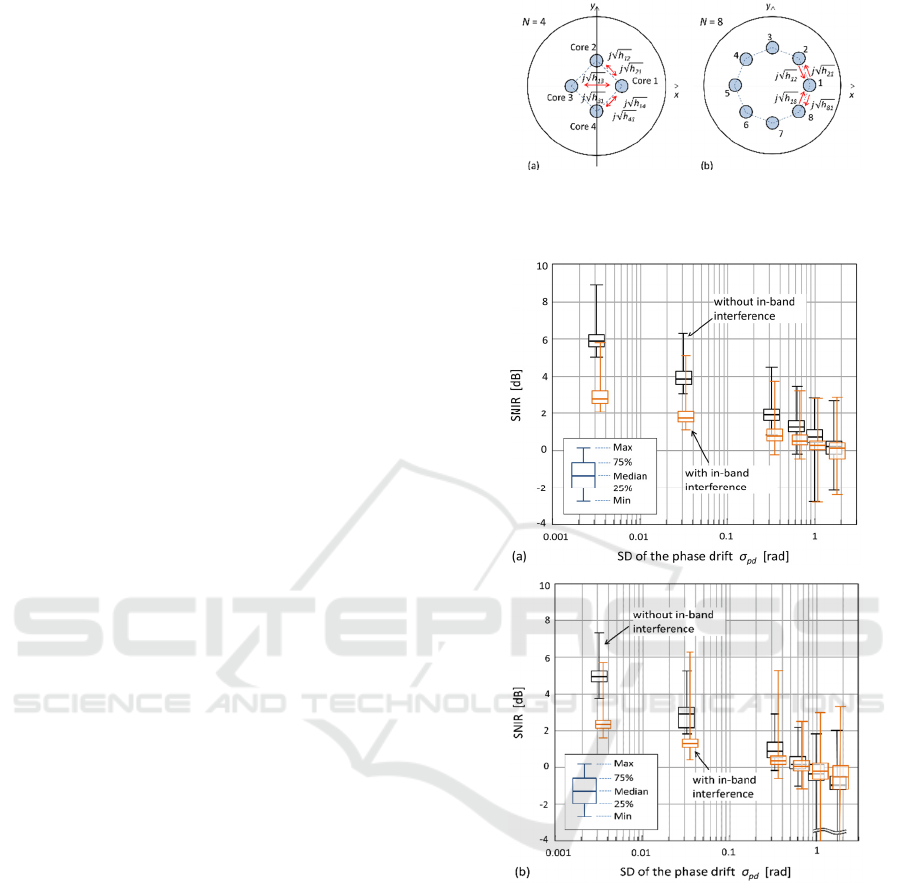
Figure 2 shows rough sketches of (a) 4-core and (b)
8-core optical fibres. All cores in each fibre are
identical. These two examples are typical of different
MCF types with (a) strongly coupled cores of h
rq
≈
1/N for q, r = 1, 2,…, N, and (b) low crosstalk between
only the nearest neighbour cores, i.e. h
qq
, h
q±1,q
≠ 0
and h
rq
≈ 0. We first discuss the coding effect in the
MCFs of the former type. Substituting h
rq
= 1/N into
Eq. (2), the output signal w
s
(t) is approximated by
w
s
(t)∝
∑
c
r
s
c
r
1
j
∑
c
r
s
c
q
1
N
q
r
N
r
1
(3)
⋯
∑
c
r
s
c
r
p
j
∑
c
r
s
c
qp
N
q
r
N
r
1
⋯
∑
∑
.
where
∑
indicates a sum of N − 1 terms over all
q except for q = r. In the case of the desired signal of
s
s
(t) at p = s in Eq. (3), we consider the amplitude
coefficient of the desired signal s
s
(t), which is
∑
∑
, and the other
terms including other signal amplitudes,
∑∑
c
rs
c
rp
+j
∑
c
rs
c
qp
N
q ≠ r
e
jβδ
r
(t)
.
N
r = 1
N
p ≠ s
Assuming the
variation of the phase drift βδ
r
(t)
is random and small,
the former terms contain non-zero values of ~N and
almost zero values because of the sum of squares of
the matrix elements and the sum of products of the
elements in different rows, respectively. The latter
terms act as noise and consist of the two sums of
products of matrix elements of different lines and rows,
with different lines and identical rows; moreover, they
are approximately zero because of the orthogonality.
Consequently, we can expect that the amplitude of the
desired signal will be higher than that of the noise
components. However, owing to the orthogonality of
coding matrices, faulty cancellation occurs when the
phase drift cannot be ignored. To estimate the impact
on the separate detection of the desired signal because
of the phase drift, we next analyse the PD output given
by,
|
w
s
(t)
|
2
∝
|
K
1
t
s
1
t
+ ⋯+K
s
t
s
s
t
+ ⋯
(4)
+
K
N
t
s
N
t
|
∑
|K
m
(t)|
2
|s
m
t
|
2
N
m
=1
+
∑∑
K
m
t
K
n
*
(t)s
m
(t)s
n
*
(t)
N
n=1
N
m
=1
,
Figure 2: Two different single-mode MCFs with (a) high
and equal CT between every core, and (b) low CT between
only nearest neighbor cores.
Figure 3: SNIR as a function of σ
pd
when the desired signals
(a) s
1
(t) and (b) s
2
(t) are obtained through 4-core fibre with
h
qr
= 0.5 (q, r = 1, 2,…, 4). The sample number is 1000 and
the box areas indicate the range within 25% above or below
the median. To ensure visibility of two overlapped bars,
orange-coloured bars are shifted slightly along x-axes.
where K
m
(t) is the amplitude coefficient of each signal
s
m
(t) described above. Assuming that every signal
exhibits the same uniform averaged power, we define
the signal to interference-and-noise ratio (SNIR)
simply as the intensity ratio of
|K
s
(t)|
2
/ (
∑∑
K
m
t
K
n
*
t
N
n
=1
N
m
=1
- |K
s
(t)|
2
) for the
desired signal s
s
(t). Here, the SNIR is composed of
the mutual access interference (MAI) and non-desired
signal components and does not include the noise
PHOTOPTICS 2016 - 4th International Conference on Photonics, Optics and Laser Technology
106
because of the PD. If the optical carriers of each
signal are fully separate, in-band interferences
because of s
m
(t)s
n
*
(t) can be neglected.
To analyse the SNIR, we assume that the phase drift
difference βδ
m
(t) follows the zero-mean normal
distribution with the standard deviation (SD) σ
pd
,
because βδ
m
(t) is mainly caused by environmental
changes around a certain mean value, and it is also
interpreted as the random phase difference of the
lights with many intercore couplings along a fibre.
Figures 3(a) and 3(b) show box plots of the SNIR as
a function of σ
pd
when the desired signals s
1
(t) and
s
2
(t) are included within w
1
(t) and w
2
(t), respectively,
and N = 4 and h
rq
= 0.5 for r, q = 1, 2, 3, 4. The sample
size is 1000 and box areas indicate the range within
25% above or below the median. Examination of Fig.
3(a) shows that the SNIR declines linearly with
increasing σ
pd
, but remains at more than 0 dB for σ
pd
< π/5 in the case of no in-band interference. When the
in-band interference, i.e. MAI, is added, the SNIR
exhibits a remarkable degradation in the region of
lower σ
pd
. This is because of the large values of the
interference components that behave as a cosine
curve within small phase differences. Fig. 3(b)
presents the data for the desired signal s
2
(t); while
these show a similar trend for SNIR values: the SNIR
values are lower than those in Fig. 3(a) by 0.5–1 dB
because of the characteristics of the coding matrix.
Summarising the results, a SNIR of more than 0 dB
can be expected for the 4-core fibre when the phase
drift is suppressed to within the σ
pd
≤ π/10 range.
However, for practical transmission, it may be
necessary to reduce or compensate the phase drift
because of the widely distributed SNIR values.
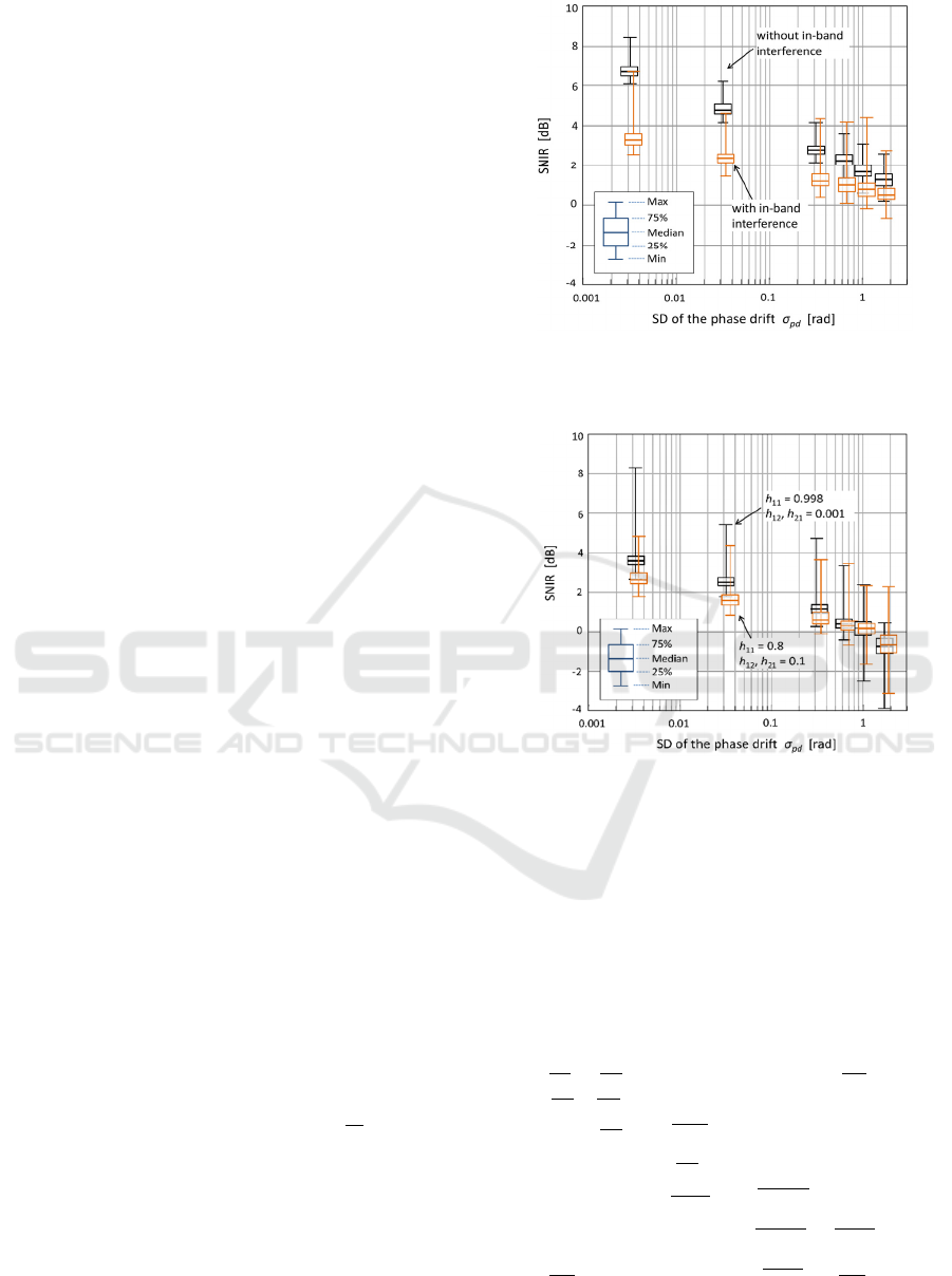
Furthermore, for the sake of comparison, we
estimate the SNIR for a fibre model in which the
matrices D and H consist of multiple matrices, i.e.
D·H =
∏
D
i
·H
i
M
i
=1
where M is the number of
intercore couplings. According to the additivity of
variance of the normal dispersion, the SD of the phase
drift at each coupling is set to be σ
pd
√
M
. Figure 4
shows the SNIR for the desired signal s
1
(t) as a
function of σ
pd
in the 4-core fibre with M = 10.
Although the SNIR rises slightly over the entire
range of σ
pd
, there is no significant difference in the
results presented in Fig. 3(a).
Figure 4: SNIR as a function of σ
pd
when the desired signal
s
1
(t) is obtained through a 4-core fibre model with multiple
connections of M = 10.
Figure 5: SNIR with in-band interferences as a function of
σ
pd
when the desired signal s
1
(t) is obtained through the 8-
core fibre with two different CT.
3.2 Coding in Use of a MCF with Weak
Coupling
Next, we analyse the coding performance for an MCF
with low CT illustrated in Fig. 2(b). For simplicity,
we assume that the CT takes a non-zero value only
between adjacent cores, i.e. h
qr
= 0 except for r = q ±
1. The elements of matrix H are given by
(5)
The output signal w
s
(t) is then written as
h
11
j
h
12
⋯ 0 ⋯ 0 j
h
1N
j
h
21
h
22
⋱ 0 ⋯⋮ 0
0 j
h
32
⋱ j
h
q-1,q
⋯ 0 ⋮
00⋱
h
qq
⋱ 00
⋮ 0 ⋯ j
h
q+1,q
⋱ j
h
N-2,N-1
0
0 ⋮⋯0 ⋱
h
N-1,N-1
j
h
N-1,N
j
h
N1
0 ⋯ 0 ⋯ j
h
N,N-1
h
NN
.
Analysis of Multicore Fibre Transmission with Space Coding Scheme
107

w
s
(t)∝
∑
h
qq
c
qs
c
q1
e
jβδ
r
t
N
q
=1
(6)
+
∑
j
h
q+k,q
c
q+k,s
c
q1
k
=±1
e
jβδ
q+k
t
s
1
(t) + ⋯
+
∑
h
qq
c
qs
c
qs
e
jβδ
q
t
N
q
=1
+
∑
j
h
q+k,q
c
q+k,s
c
qs
k
=±1
e
jβδ
q+k
t
s
s
(t) +⋯
+
∑
h
qq
c
qs
c
qN
e
jβδ
q
t
N
q
=1
+
∑
j
h
q+k,q
c
q+k,s
c
qN
k
=±1
e
jβδ
q+k
t
s
N
(t).
Assuming that βδ
r
(t) is negligible between the nearest
neighbour cores, the amplitude of the desired signal
w
s
(t) is given by
∑
h
qq
c
qs
c
qs
e
jβδ
q
t
N
q
=1
+
∑
j
h
q+k,q
c
q+k,s
c
qs
k
=±1
e
jβδ
q+k
t
. The maximum
value of the first term is N
h
qq
, and the second term
approaches zero because of the orthogonality of
matrix C. Moreover, for the other signal components,
the coefficient
∑∑
h
qq
c
qs
c
qm
e
jβδ
q
t
+
N
q
=1
m
≠s
∑
j
h
q+k,q
c
q+k,s
c
qm
k
=±1
e
jβδ
q+k
t
approaches zero.
Consequently, we can expect the separate detection of
the desired signal for a small phase drift. For this type
of MCF, we can expect a better coding gain because
the number of cores, i.e. code length, and coupling
pairs that act as noise sources are correspondingly
higher and lower than those for the MCF with strong
coupling discussed above. Using Eqs. (4) and (6), the
SNIR is calculated for the case of the 8-core optical
fibre model. Figure 5 shows the SNIR as a function
of σ
pd
when the power transfer ratios are (a) h
12
= 0.1
and h
11
= 0.8, and (b) h
12
= 0.001 and h
11
= 0.998,
equivalent to the extinction ratios of −6 and −17 dB,
respectively. It is clear that the SNIR declines with
increasing σ
pd
, and remains positive in the σ
pd
≤ π/10
range. The SNIR is improved by ~1 dB in the case of
smaller h
12
, but this case is considered to be fairly
insensitive to CT. Furthermore, compared to the
results in Fig. 5 and Fig. 3(a), we can observe a slight
improvement of ~1 dB for the SNIR values shown in
Fig. 5. The improvement is lesser than expected,
because the fault cancellations for many undesired
signal components are caused by the phase drifts and
these weaken the coding gain.
4 CONCLUSIONS
We have analysed the space coding characterization in
MCF transmission with strong and weak intercore
couplings. Separate detection for the desired signal can
be achieved without optical MIMO processing with an
SNIR of more than 0 dB, achieved when the phase drift
of the optical signal in each core is suppressed,
typically to within ~π/10. In future studies, we will
perform simulation experiments in an in-depth
investigation and evaluate bit error rate characteristics
as well as identify a procedure for control of the phase
drifts in MCF transmission.
REFERENCES
Arik, S. Ö., Askarov, D., Kahn, J. M., 2013. ‘Effect of mode
coupling on signal processing complexity in mode-
division multiplexing,’ J. Lightw. Technol., vol. 31, pp.
423–431.
Kitayama, K., Wang, X., Wada, N., 2006. ‘OCDMA over
WDM PON–Solution path to gigabit-symmetric FTTH,’
J. Lightw. Technol, vol. 24, pp. 1654–1662.
Hayashi, T., Taru, T., Shimakawa, O., Sasaki, T., Sasaoka,
E., 2011. ‘Design and fabrication of ultra-low crosstalk
and low-loss multi-core fiber,’ Opt. Exp., vol. 19, pp.
16576–16592.
Hernandez, V. J., Mendez, A. J., Bennett, C. V., Lennon,
W. J., 2005. ‘Simple robust receiver structure for
gigabit Ethernet O-CDMA using matrix codes,’ J.
Lightw. Technol., vol. 23, pp. 3105–3110.
Mendez, A. J., Gagliardi, R. M., Hernandez, V. J., Bennett, C.
V., Lennon, W. J., 2003. ‘Design and performance analysis
of wavelength/time (W/T) matrix codes for optical
CDMA,’ J. Lightw. Technol., vol. 21, pp. 2524–2533.
Ryf, R., Essiambre, R. –J., Randel, S., Gnauck, A. H., Winzer,
P. J., Hayashi, T., Sasaki, T., 2011. ‘MIMO-based
crosstalk suppression in spatially multiplexed 56-Gb/s
PDM-QPSK signals in strongly-coupled 3-core fibre,’
IEEE Photon. Technol. Lett., vol. 23, pp. 1469-1471.
Sakaguchi, J., Puttnam, B. J., Klaus, W., Awaji, Y., Wada,
N., Kanno, A., Kawanishi, T., Imamura, K., Inaba, H.,
Mukasa, K., Sugizaki, R., Kobayashi, T., Watanabe, M.,
2013. ‘305 Tb/s space division multiplexed
transmission using homogeneous 19-core fibre,’ J.
Lightw. Technol., vol. 31, pp. 554-562.
Sakamoto, T., Mori, T., Wada, M., Yamamoto, T.,
Yamamoto, F., 2015. ‘Coupled multicore fiber design
with low intercore differential mode delay for high-
density space division multiplexing,’ J. Lightw.
Technol., vol. 33, pp. 1175–1181.
Shah, A. R., Hsu, R. C. J., Tarighat, A., Sayed, A. H., Jalali,
B., 2005. ‘Coherent optical MIMO (COMIMO),’ J.
Lightw. Technol., vol. 23, pp. 2410–2419.
Winzer, P. J., Gnauck, A. H., Konczykowska, A., Jorge, F.,
Dupuy, J.-Y., 2011. ‘Penalties from in-band crosstalk
for advanced optical modulation format,’ Proc. ECOC,
2011, Tu.5.B.7.
Xia, C., Amezcua-Correa, R., Antonio-Lopez, N. B. E.,
Arrioja, D. M., Schulzgen, A., Richardson, M., Liñares,
J., Monteo, E., Zhou, X., Li, G., 2012. ‘Hole-assisted
few mode multicore fiber for high-density space-
division multiplexing,’ IEEE Photon. Technol. Lett.,
vol. 24, pp. 1914–1917.
PHOTOPTICS 2016 - 4th International Conference on Photonics, Optics and Laser Technology
108
