
One Shot Photometric Stereo from Reflectance Classification
Toshiya Kawabata, Fumihiko Sakaue and Jun Sato
Department of Computer Science and Engineering, Nagoya Institute of Technology, Nagoya 466-8555, Japan
Keywords:
Photometric Stereo, Multi-band Imaging, Multi-band Lighting, Photometric Analysis.
Abstract:
3D reconstruction of object shape is one of the most important problem in the field of computer vision. Espe-
cially, estimation of normal orientation of object surface is useful for photo-realistic image rendering. For this
estimation, the photometric stereo is often used. However, it requires multiple images taken under different
lighting conditions in the same pose, and thus, we cannot apply it to moving objects in general. In this pa-
per, we propose a one-shot photometric stereo for estimating surface normal of moving objects with arbitrary
textures. In our method, we estimate surface orientation and reflectance property simultaneously. For this
objective, reflectance data set is used for decreasing DoF (Degree of Freedom) of estimation. In addition, we
classify reflectance property of an input image into limited number of classes. By using the prior knowledge,
our method can estimate surface orientation and reflectance property, even if input information is not sufficient
for the estimation.
1 INTRODUCTION
In the field of computer vision, 3D reconstruction
is one of the most important problems. In ordinary
case, several numbers of images are taken under dif-
ferent imaging condition, and then, 3D shape is re-
constructed from these images. In general, stereo
method from multiple cameras is used for 3D re-
construction(Agarwal et al., 2011; Newcombe et al.,
2011). In these methods, correspondences are de-
tected from images, and 3D shape is reconstructed
from the correspondences(Hartley and Zisserman,
2000). In particular, multi-baseline stereo method
with bundle adjustment is widely used for 3D recon-
struction(Agarwal et al., 2011). Furthermore, dense
3D reconstruction by using a moving camera is also
proposed(Newcombe et al., 2011).
The 3D reconstruction is useful for obtaining 3D
shape of objects, since we need just cameras. How-
ever, the accuracy of results is often not sufficient for
recovering surface orientation. The surface orienta-
tion can be estimated by differentiating 3D shapes,
and thus we need very accurate 3D shapes for ob-
taining accurate surface orientations. The surface re-
construction is important for synthesizing realistic 3D
graphics because photometric property, such as shad-
ing, on object depends mostly on surface orientations.
Thus, accurate estimating methods of surface orienta-
tion are required.
The photometric stereo method(Chen et al., 2011;
Anderson et al., 2011) is widely used for surface ori-
entation estimation. The method can estimate surface
orientation directly from a set of images taken under
different lighting conditions. In ordinary case, a cam-
era and a target object are fixed and just lighting con-
dition changes for the estimation.
Although the method works well for static scenes,
it cannot work for dynamic scenes, since images are
taken under not only different lighting conditions but
also different poses in the case of dynamic scenes.
Thus, we cannot reconstruct surface orientation of dy-
namic scenes from these images.
For reconstructing 3D surface of dynamic scenes,
we need to obtain multiple images under different
lighting conditions simultaneously. For this objec-
tive, some methods are recently proposed. Chen et
al.(Chen et al., 2011) proposed image demultiplex-
ing method for photometric stereo. In this method,
special periodic patterns are projected from projec-
tors to target scene simultaneously. By demultiplex-
ing an observed image, we can obtain multiple im-
ages taken under different lighting from a single im-
age. Although the method works well even if the
target scenes change dynamically, it does not work
when scene include complex texture. Anderson et
al.(Anderson et al., 2011) proposed a method using
multiple colored lights. In this method, a single im-
age is divided into multiple images illuminated un-
der different conditions by using color information.
Furthermore, Brostow et al.(Brostow et al., 2011) ex-
620
Kawabata, T., Sakaue, F. and Sato, J.
One Shot Photometric Stereo from Reflectance Classification.
DOI: 10.5220/0005718406180625
In Proceedings of the 11th Joint Conference on Computer Vision, Imaging and Computer Graphics Theory and Applications (VISIGRAPP 2016) - Volume 3: VISAPP, pages 620-627
ISBN: 978-989-758-175-5
Copyright
c
2016 by SCITEPRESS – Science and Technology Publications, Lda. All rights reserved

pand the method for color objects. Fyffe et al.(Fyffe
et al., 2011) also proposed one shot stereo using multi
spectral (multi-band) lighting. Although they esti-
mate surface normal and reflectance simultaneously,
their method needs 6 band light sources. In addition,
their method can estimate only RGB reflectance.
In this paper, we propose a new one shot photo-
metric stereo method for reconstructing dynamic 3D
surfaces. In this method, we use multiple lights which
have different spectrum to each other. The spectral
components are not only ordinary red, green and blue,
but also the other kinds of colors. By using the mul-
tiple colors, much larger number of information than
the number of unknown parameters, e.g. surface ori-
entation and reflectance, can be used for estimating
the unknown parameters. Furthermore, we achieve
simultaneous estimation of surface orientation and re-
flectance from small number of light sources by using
reflectance classification. By this classification, DoF
of reflectance in a whole image is drastically reduced,
and thus, we can estimate reflectance and surface ori-
entation more efficiently.
2 PHOTOMETRIC STEREO
Photometric stereo for surface reconstruction is
widely studied and various methods were proposed.
Although the photometric stereo was applied to com-
plex reflection models(Brostow et al., 2011) in recent
years, we need to estimate additional parameters in
order to deal with complex reflection models. Thus,
in this paper, we consider a simple reflection model
for surface reconstruction.
2.1 Reflection Model
We first explain basic photometric stereo for surface
reconstruction. In this paper, we assume that reflec-
tion of surface can be described by Lambert model,
in which observed intensity I can be described by a
surface normal n and lighting direction s as follows:
I = max(Eρn
⊤
s,0) (1)
where E indicates a radiance of the light and ρ in-
dicates a reflectance of object surface. If there is no
shadow in the scene, Eq.(1) can be rewritten as fol-
lows:
I = Eρn
⊤
s (2)
If a light source is sufficiently far from the scene,
we can describe all the intensities in an image by
using a single lighting direction s linearly, which is
called infinite light reflection model. The infinite light
reflection model is widely used for photometric anal-
ysis since it simplifies problems drastically and en-
hance the stability of method. Thus we in this paper
use the infinite light reflection model.
2.2 Reconstruction of Normal
Orientation
We next consider surface reconstruction from images
taken under different lighting conditions. Let s
i
de-
note a lighting direction for i-th image. Then, the in-
tensities of M images can be described as follows:
I
1
I
2
.
.
.
I
M
=
E
1
s
⊤
1
E
2
s
⊤
2
.
.
.
E
M
s
⊤
M
ρn (3)
where I
i
and E
i
are an intensity and a radiance for
i-th image. If the lighting information E
i
and s
i
is
calibrated, a surface orientation n can be estimated
linearly by the least means square method as follows:
ρn =
E
1
s
⊤
1
E
2
s
⊤
2
.
.
.
E
M
s
⊤
M
+
I
1
I
2
.
.
.
I
M
(4)
where A
+
is the pseudo inverse of A and A
+
=
(A
⊤
A)
−1
A
⊤
. The norm of a surface orientation n is
equal to 1, and thus, ρ and n can be separated easily.
In this estimation, DoF of estimated parameters is
3 and they are a reflectance and two parameters of sur-
face. Although surface orientation n has 3 variables,
DoF of it is 2 because a norm of it is constrained.
Therefore, we can estimate these parameters from 3
or more than 3 images taken under different illumina-
tions. It indicates that we cannot estimate the param-
eters from a single image by the photometric stereo
method.
3 ONE SHOT PHOTOMETRIC
STEREO
3.1 Intensity Representation by Light
Spectrum
In this paper, we expand the photometric stereo for
multi-band lighting. In this section, we describe ob-
served intensity from a viewpoint of spectrum. Let
r(λ) denotes a reflectance spectrum, e(λ) denotes a
light spectrum and x(λ) denotes a spectral response
One Shot Photometric Stereo from Reflectance Classification
621

of an observing camera. In this case, an observed in-
tensity I can be described as follows:
I = E
Z
e(λ)r(λ)x(λ)dλn
⊤
s (5)
where E denotes radiance of light, and, n and s in-
dicates surface orientation and lighting direction. A
reflectance ρ can be defined as follows:
ρ =
Z
e(λ)r(λ)x(λ)dλ (6)
Thus, Eq.(5) is equivalent to Eq.(1). Note that, re-
flectance ρ includes not only reflectance spectrum but
also light spectrum and spectral response of camera in
this paper.
3.2 Multi-band Imaging under
Multi-band lighting
As descried in the previous section, we can obtain
different equations from a single image when we use
multiple lights which have different spectrum. There-
fore, we can reconstruct surface normals from a single
image. For this objective, we first consider the case
where there are some light sources which have dif-
ferent light spectrum to each other. When the scene
is observed by multiple sensors which have different
spectral response, observed intensity I
j
of j-th sensor
can be described as follows:
I
j
= E
i
∑
i
Z
e
i
(λ)r(λ)x
j
(λ)dλn
⊤
s
i
(7)
where e
i
indicates a light spectrum of i-th light and
x
j
indicates a spectral response of j-th sensor. The
reflectance ρ
ij
under i-th light for j-th sensor can is
defined as follows:
ρ
ji
=
Z
e
i
(λ)r(λ)x
j
(λ)dλ (8)
By using the reflectance ρ
ij
, Eq.(7) can be rewritten
as follows:
I
j
= E
i
ρ
ji
n
⊤
s
j
(9)
When E
i
is equal to 1, we finally obtain simultaneous
equations as follows:
I
1
.
.
.
I
M
=
ρ
11
··· ρ
1N
.
.
.
ρ
M1
··· ρ
MN
s
⊤
1
.
.
.
s
⊤
N
n (10)
If we can solve the simultaneous equations, we can
estimate the surface orientation n from a single image.
As described above, we may think that we can es-
timate surface orientations from a single multi-band
image. However, we cannot do it unfortunately, be-
cause the number of variable such as reflectance in-
creases when the number of bands increases as shown
in Eq.(10). Thus, we cannot obtain unique surface
orientations from a multi-band image without any ad-
ditional constraint.
3.3 Photometric Stereo with Reflectance
Database
In order to solve Eq.(10) for estimating surface ori-
entation, we add other constraints. We first consider
a constraint on reflectance of object surface. Re-
flectance parameters are determined by reflectance
spectrum r(λ). It is known that arbitrary spectrum can
be represented by linear summation of limited number
of bases. The fact indicates that reflectance can also
be described by small number of parameters. In this
section, we assume that a set of reflectance of the ob-
ject can be obtained beforehand. However, the object
is non-rigid and its surface normals change in each
time instant, and thus we have to estimate them si-
multaneously. Under this assumption, Eq.(10) can be
rewritten as follows:
I
1
.
.
.
I
M
= R(s)
s
⊤
1
.
.
.
s
⊤
N
n (11)
where R(s) is a matrix which represents a set of re-
flectance determined by a parameter s.
In this equation, the number of unknown variables
is 3, i.e. two parameters of a surface normal n and
a parameter s, if we know lighting direction. Thus,
we can estimate these variables from 3 or more than
3 band images.
For representing a manifold of reflectance, we use
reflectance database. This database consists of a set
of reflectance of target scene, and then, we should just
choose a proper reflectance from the database for pa-
rameter estimation. In this method, the database ef-
ficiently works for estimating the surface orientation,
although we need to prepare the database beforehand.
3.4 Smoothness Constraint
We next add smoothness constraint with surface ori-
entation. In ordinary case, object surface is ap-
proximately smooth, and thus, surface orientations
among neighbor pixels should be similar to each
other. Therefore, we define a cost function about
smoothness E
xy
s
at pixels (x,y) as follows:
E
xy
s
=
x+1
∑
l=x−1
y+1
∑
m=y−1
||n
xy
− n
lm
|| (12)
When E
s
is minimized at all pixel, object surface be-
come smooth.
3.5 Minimization of Cost Function
In the previous sections, we defined some constraints
for surface orientation estimation. By combining
VISAPP 2016 - International Conference on Computer Vision Theory and Applications
622

these constraints, we can finally obtain a cost func-
tion for surface orientation estimation as follows:
E =
∑
x
∑
y
(||I
xy
j
−
ˆ
I
xy
j
(n,s)||
2
+ wE
xy
s
) (13)
where w is a weight and I
xy
j
is an observed inten-
sity at pixel (x,y) for j-th band sensor.
ˆ
I
xy
j
(n,s) is
a reconstructed intensity from estimated parameters n
and s. By minimizing the equation, we can estimate
a surface normal n and a reflectance R(s) simultane-
ously. However, the minimization is not so easy be-
cause R(s) is not linear and continuous.
In order to minimize the function, we use sepa-
rated estimation. In this estimation, we minimize only
first term pixel by pixel as follows:
E
xy
1
= ||I
xy
j
−
ˆ
I
xy
j
(n,s)||
2
(14)
In this estimation, we select a reflectance from the
database and estimate surface orientation n as a re-
sult of LM solution of Eq.(10). After that, we evalu-
ate selected reflectance set by Eq.(14). A reflectance
which provides the lowest E
1
is the estimated param-
eters and n estimated by this parameter is the result of
estimation.
After that, we estimate surface orientation with
smoothness constraint. In this estimation, reflectance
parameter s is fixed. In addition, we define the esti-
mation weight as follows:
w
xy
= 1−
E
xy2
1
E
xy2
i
+ σ
(15)
where σ determines distribution of weight. Figure
1 shows this function when σ = 1. This weight de-
scribes the reliability of s. By using the weight, we
define a cost function as follows:
E
2
=
∑
x
∑
y
(w
xy
||I
xy
j
−
ˆ
I
xy
j
(n,s)||
2
+ wE
xy
s
) (16)
By using this function, surface orientation is esti-
mated from the smoothness constraint when reliabil-
ity of s is low. This cost function is just a linear equa-
tion, and thus it can be solved by the LMS method.
After this orientation estimation, reflectances are fi-
nally chosen by using the estimated orientations, and
thus orientations and reflectances are estimated with
smoothness constraint.
By this proposed method, we can estimate re-
flectance and surface orientation simultaneously from
a single multi-band image.
Figure 1: Weight function 1−
x
2
x
2
+1
.
4 REFLECTANCE ESTIMATION
USING REFLECTANCE
CLASSIFICATION
4.1 Reflectance Representation by
Linear Combination of Bases
We next consider the case where reflectance proper-
ties are unknown completely. We do not utilize the
particular reflectance database for a target object, and
thus, we should use other prior knowledge. For this
objective, a general reflectance database(Kohonen
et al., 2005) can be used. The general reflectance
database includes various reflectance properties in
natural environment, and thus, we can choose appro-
priate reflectance property from the database. How-
ever, this database includes a lot of reflectances, thus,
it is not so easy and requires large computational cost
to choose proper reflectance.
In order to avoid the problem, we compress the
database. In general, it is known that most of the re-
flectance property in natural environment can be rep-
resented linearly by a small number of bases. There-
fore, we compress the database by using a principal
component analysis (PCA). By using the linear bases
from the PCA, reflectance properties in the natural en-
vironment can be represented by linear combination
of about 5 principal bases. Therefore, we can estimate
arbitrary reflectance property in natural environment
by estimation of only small number of coefficients for
each bases. In this paper, the number of bases is de-
scribed by K.
4.2 Reflectance Classification
As described in the previous section, we can repre-
sent and estimate arbitrary reflectance property from
small number of parameters. However, if we do not
have sufficient number of spectral band, we cannot
estimate reflectance property and surface normal ori-
entation simultaneously. For example, when we have
3 band image, we cannot estimate reflectance and sur-
face normal because DoF of input image is 3 and it is
smaller than the DoF of estimating parameters 2+ K
One Shot Photometric Stereo from Reflectance Classification
623

(2 for surface orientation and K for reflectance).
In order to avoid the problem, we utilize a new
prior knowledge. In general, a number of reflectance
property in a object is limited. Therefore, we should
estimate limited number of reflectance properties
from a whole image. Under this constraint, we can
estimate reflectance properties and surface orientation
simultaneously from a single image. For example,
when there are L kinds of properties in an input im-
ages which have N pixels, the DoF of estimating pa-
rameters are KL + 2N. Therefore, we can estimate
surface orientation from an M-band image when MN
is larger than KL+ 2N.
4.3 Simultaneous Estimation of Surface
Orientation and Reflectance
In order to minimize the cost function under above-
mentioned constraint, we utilize RANSAC like opti-
mization method. In this section, we explain detail of
this optimization method.
At first, minimum number of points for estimat-
ing reflectance and surface orientation are chosen ran-
domly , and then, the surface orientation and re-
flectance are estimated by minimizing a cost function.
The cost function E
1
is defined as follows:
E
1
=
∑
i
∑
j
||I
ij
− n
⊤
i
s
j
R(c)||
2
,||n
i
|| = 1 (17)
where I
ij
is the intensity of i-th point illuminated by
j-th light, c is a set of coefficients of reflectance and
R(c) indicates reflectance obtained from c. When the
set of pixels have the same reflectance, E
1
becomes
very small and proper surface normals n
i
are esti-
mated. On the other hand, the cost E
1
cannot become
small if the reflectance properties of a set of pixels are
different from each other. Therefore, we choose can-
didates of reflectance when the cost E is smaller than
a threshold θ
1
. Note, DoF of estimated parameters is
L+2O when O denotes number of points and DoF of
input image is MO. Thus, O satisfies L/(M − 2).
We next confirm the candidate reflectance from
the previous step by using consensus. In this step, sur-
face orientation for every pixel are estimated by using
candidate reflectance
ˆ
R(c), and then, the candidate is
evaluated as follows:
E
2
= δ
∑
k
∑
j
||I
kj
− n
k
s
j
ˆ
R
j
(c)||
2
(18)
δ(x) =
1 if x < θ
2
0 otherwise
(19)
where θ
2
is a threshold. When the evaluation value E
2
is larger than a threshold θ
3
, reflectance
ˆ
R is chosen
as reflectance of the target object.
By applying the process iteratively, a set of re-
flectance is obtained. At last, we optimize surface
orientation by using the estimated reflectance. In this
step, the following cost functions are minimized pixel
by pixel
E
3
=
∑
j
||I
j
− n
⊤
s
j
ˆ
R
l
j
(c)||
2
(20)
where
ˆ
R
l
j
indicates j-th band reflectance of l-th re-
flectance property. The surface orientation n and a
reflectance
ˆ
R which minimize the cost are selected as
the final estimation results. By using the re-estimation
step, we can correct error estimation in the first step,
and thus, we can obtain proper orientation and re-
flectance for each pixel.
5 EXPERIMENTAL RESULTS
FROM SPECIFIC DATABASE
We estimated reflectance and surface orientation by
the proposed method. We first show experimental re-
sults by using a specific reflectance database as de-
scribed in 3.3.
5.1 Environment
In this experiment, reflectance database was con-
structed from a target object, at first. After that, sur-
face normal of the target object was estimated in dif-
ferent pose using the reflectance database. We used
3 projectors as light sources in the experiment. The
projectors were set as shown in Fig.2(a) and emit red,
green and blue lights simultaneously. Directions of
the light sources from a target object were calibrated
beforehand. A color camera is set in front of a tar-
get object as shown in Fig.2(a). The target object of
this experiment is shown in Fig.2(b). The database
of reflectance was constructed from surface orien-
tation estimated by the standard photometric stereo
method (which is not one shot method) and images
taken under each single color light. Under this en-
vironment, surface orientation was estimated by the
proposed method.
5.2 Reconstructed Result
We first show an input image in Fig.3. This image was
illuminated by 3 lights simultaneously. From the im-
age, surface orientation was reconstructedas shown in
Fig.4(a). In this figure, surface orientations are repre-
sented by color referring to the left top measure in the
image. Fig.4(b) shows the estimated reflectance. In
this figure, only diagonal components of R is shown
by color.
VISAPP 2016 - International Conference on Computer Vision Theory and Applications
624

(a) Experimental environment (b) Target object
Figure 2: Experimental environment and target object.
Figure 3: Input image: The object was illuminated by 3
lights which have different spectrum to each other.
(a) Surface normal (b) Reflectance
Figure 4: Surface normal and reflectance obtained from the
proposed method.
(a) Ground truth (b) Estimation error
Figure 5: Comparison between proposed method and ordi-
nary method: (a) indicates the ground-truth of surface nor-
mals, and (b) indicates estimated error of our method.
In order to evaluate the proposed method, we
compared the result with surface orientations recon-
structed by the ordinary method. In the ordinary
photometric method, 3 images are taken separately
under different lighting conditions. The same light
sources as the proposed method were used and they
emit white light, respectively. The result of the ordi-
Figure 6: Five principal bases for representing arbitrary re-
flectance. The bases were computed by PCA from Munsell
color data set.
nary method and the difference between the proposed
method and the ordinary method is shown in Fig.5.
In Fig.5(b), intensities of error image represent an-
gles between surface normals estimated by these two
methods. The average of angle errors was 14.7 de-
grees. The result indicates that our proposed method
can reconstruct surface orientation accurately from a
single image.
6 EXPERIMENTAL RESULT BY
LARGE SCALE DATABASE
6.1 Environment
We next show experimental results using large scale
database. In this experiment, The Munsell color data
set(Kohonen et al., 2005) was used for reflectance
database. From the database, 5 principal bases were
computed by PCA. A cumulative contribution ratio
of these five bases was 99.1%. The spectrums of the
reflectance bases are shown in Figure—6 shows spec-
tral reflectance of each principal bases. An arbitrary
reflectance is represented by combining the bases.
Experimentalenvironment for taking input images
are shown in Fig.7. In this experiment, 5 projec-
tors were used as light sources. The each projector
equipped different spectrum band pass filters. Spec-
trum distribution of the filters are shown in Fig.8. In
order to obtain multi-band images, a single gray scale
camera and 5 band pass filters were used instead of
a real multi-band camera. Spectrum distribution of
each band pass filter is correspond to a filters for light
sources, and thus, we can separate multi-band image
to single band image illuminated by a light source eas-
ily.
Input images were taken with changing band-pass
filters. Figure 9 shows examples of input images for
each band. In this figure, intensities in each spectrum
band is shown as images (a), and image (b) shows ob-
served result by an ordinary RGB camera. The image
One Shot Photometric Stereo from Reflectance Classification
625
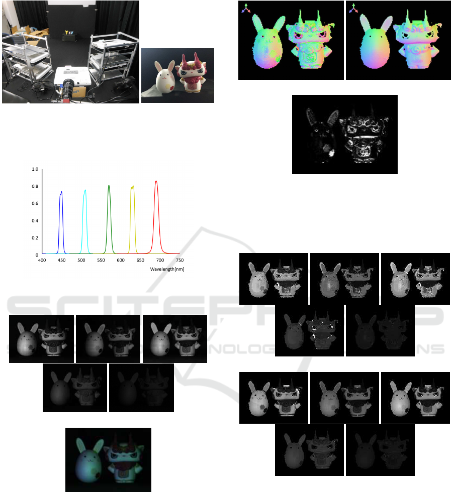
(a) Environment
(b) Target objects
Figure 7: Experimental environment and target objects:
Five projectors were set in front of target objects. The pro-
jectors equipped different spectral band-pass filters.
Figure 8: Spectral distributions of band pass filters for light
sources.
(a) Intensities on each spectrum band
(b) Observed image by RGB camera
Figure 9: Input multi-band image: Images (a) indicate in-
tensities on each spectrum band shown in Fig.8 and image
(b) shows observed image by ordinary RGB camera.
(b) was not used for estimation, and thus, a 5 band
image at (a) was used for estimation by our proposed
method.
From the images and the 5 principal bases, surface
normal and reflectance distribution of each pixel were
estimated by the proposed method.
(a) Estimated surface (b) Ground truth
(c) Estimated errors
Figure 10: Surface orientation estimation result: (a) shows
estimated result by our proposed method and (b) shows
ground truth estimated from normal photometric stereo. Im-
age (c) shows angle between estimated result and ground-
truth.
(a) Estimated reflectance on each spectrum band.
(b) Ground truth
Figure 11: Reflectance estimation result: images (a) show
result by our method and images (b) show ground truth from
ordinary photometric stereo.
6.2 Estimated Results
Figure 10 shows estimated surface orientation by the
proposed method. In this figure, (a) shows estimated
result by our method, (b) shows ground truth from
an ordinary photometric stereo, and (c) shows an-
gles between estimated result and ground truth. From
these results, the surface orientation can be estimated
VISAPP 2016 - International Conference on Computer Vision Theory and Applications
626

roughly except depth and image edge. At the depth
edge, the orientation estimation could not work well
because reflectance of the input image was changed
drastically. In this case, the reflectance cannot be rep-
resented by the combination of principal bases, and
thus, reflectance and orientation estimation could not
work well.
Figure 11 shows estimated reflectance by the pro-
posed method. In this figure, the estimated re-
flectance (a) was computed from estimated coeffi-
cients of bases, and the ground truth (b) was estimated
from ground-truth orientation and input intensities in
each band. In this result, our estimated results are
similar to the ground truth reflectance. As similar to
the orientation estimation, the estimated result is not
stable at image/depth edge by the above mentioned
reason. However, the reflectance can also be esti-
mated in whole image roughly. The results show that
the proposed method can estimate not only surface
orientation, but also reflectance.
7 CONCLUSION
In this paper, we proposed a one-shot photometric
stereo for estimating surface orientations with arbi-
trary textures. In our method, we used multiple lights
with different light spectrum and a multi-band cam-
era. In order to simplify the reflectance estimation, we
used a reflectance database. By using the database, re-
flectance estimation can be achieved by the selection
of reflectance and estimation of small number of co-
efficients. In addition, we utilized reflectance classifi-
cation, so that the DoF of estimation in whole image
is decreased drastically. Therefore, our method can
estimate reflectance and surface orientation simulta-
neously from smaller number of color band than ex-
isting methods. Experimental results show that our
method can reconstruct surface from a single multi-
band image. The method is useful for reconstructing
surface of non-rigid moving objects and it can be ap-
plied to synthesizing real objects into 3D graphics.
REFERENCES
Agarwal, S., Furukawa, Y., Snavely, N., Simon, I., Curless,
B., Seitz, S. M., and Szeliski, R. (2011). Building
rome in a day. Commun. ACM, 54(10):105–112.
Anderson, R., Stenger, B., and Cipolla, R. (2011). Color
photometric stereo for multicolored surfaces. In Proc.
ICCV2011, pages 2182–2189.
Brostow, G., Hernandez, C., Vogiatzis, G., Stenger, B., and
Cipolla, R. (2011). Video normals from colored lights.
Trans. PAMI, 33(10):2104–2114.
Chen, C., Vauero, D., and Turk, M. (2011). Illumination de-
multiplexing from a single image. In Proc. ICCV2011,
pages 17–24.
Fyffe, G., Yu, X., and Debevec, P. (2011). Single-shot pho-
tometric stereo by spectral multiplexing. In Proc. In-
ternational Conference on Computational Photogra-
phy, pages 1–6.
Hartley, R. and Zisserman, A. (2000). Multiple View Geom-
etry in Computer Vision. Cambridge University Press.
Kohonen, O., Parkkinen, J., Jaaskelaienen, T., and Parkki-
nen, J. (2005). Databases for spectral color science.
In 10th Congress of the International Colour Associ-
ation, pages 1649–1652.
Newcombe, R., Lovegrove, S., and Davison, A. (2011).
Dtam: Dense tracking and mapping in real-time. In
Proc. ICCV2011, pages 2320–2327.
One Shot Photometric Stereo from Reflectance Classification
627
