
ZMP Trajectory from Human Body Locomotion Dynamics Evaluated by
Kinect-based Motion Capture System
Igor Danilov, Bulat Gabbasov, Ilya Afanasyev and Evgeni Magid
Intelligent Robotic Systems Laboratory (LIRS), Innopolis University, Universitetskaya 1, Innopolis, 420500, Russia
Keywords:
Motion Capture (MoCap), Zero Moment Point (ZMP), Kinect Sensor, Biomechanical Analysis of Human
Locomotion, Multi-depth Sensor Video Recording.
Abstract:
This article presents the methods of zero moment point (ZMP) trajectory evaluation for human locomotion
by processing biomechanical data recorded with Kinect-based motion capture (MoCap) system. Our MoCap
system consists of four Kinect 2 sensors, using commercial iPi soft markerless tracking and visualization
technology. We apply iPi Mocap Studio software to multi-depth sensor video recordings, acquiring visual and
biomechanical human gait data, including linear and angular coordinates, velocities, accelerations and center
of mass (CoM) position of each joint. Finally, we compute ZMP and ground projection of the CoM (GCOM)
trajectories from human body dynamics in MATLAB by two methods, where human body is treated as (1)
a single mass point, and (2) multiple mass points (with following ZMP calculation via inertia tensor). The
further objective of our research is to reproduce the human-like gait with Russian biped robot AR-601M.
1 INTRODUCTION
The history of humanoid robotics is directly corre-
lated with the active exoskeletons development. Even
though one of the first exoskeleton was created al-
most 50 years ago, in 1969, under the leadership of
Yugoslav scientist Miomir Vukobratovic (Vukobra-
tovic and Juricic, 1969), humanoid robotics related
research topics keep attracting significant attention
of scientists as humanoid locomotion is still too far
from human walking stability and energy efficiency
(Larsen and Stoy, 2011).
Both humans and humanoids are underactuated
systems with no actuation between a foot and support-
ing surface (Dasgupta and Nakamura, 1999). In or-
der to develop energy-efficient locomotion algorithms
for a humanoid, a human gait analysis should be per-
formed (Asano and Luo, 2008). Taking into account
significant differences between a human and a hu-
manoid it is not feasible to apply a human gait directly
to a robot (Field et al., 2009). These differences in-
clude distinct amount of Degrees of Freedom (DoFs)
and skeletons, different mass distribution and CoM
position, limited capabilities of humanoids relatively
to humans in terms of joint constraints (position, ve-
locity and acceleration). Thus, there is no direct map-
ping of human relative positions to the robot and kine-
matic mismatch requires kinematic corrections with
calculating the joint angle trajectories. At the same
time to keep locomotion balance an advanced control
should be applied to the robot, overcoming problems
of underactuation and dynamic mismatch (Dasgupta
and Nakamura, 1999; Naksuk et al., 2005).
Nevertheless, a number of research teams re-
ported successful automatic generation of robot walk-
ing from human walking data through different math-
ematical models of locomotion control - analysis of
MoCap data of a human locomotion provided certain
human locomotion outputs, which were further im-
plemented into robotic bipedal locomotion. Sinnet et.
al. (Sinnet et al., 2011) introduced canonical human
walking functions, which were used to form a linear
spring-damper system to estimate human-walking be-
havior. Chalodhorn et al. (Chalodhorn et al., 2007)
described a mapping of a human gait data (obtained
from MoCap data) onto a body skeleton, applying in-
verse kinematics procedure; this was followed by us-
ing principal component analysis (PCA) to reduce di-
mensionality of the joints space, building 3D motion
space representation of kinematic postures.
As far as the terms of static (GCOM) and dy-
namic (ZMP) stabilities (Mrozowski et al., 2007) can
be used to biped and human locomotion balance re-
search, we are going to apply obtained with a Mo-
Cap system human locomotion data for a humanoid
robot balancing. This could be realized by adapt-
162
Danilov, I., Gabbasov, B., Afanasyev, I. and Magid, E.
ZMP Trajectory from Human Body Locomotion Dynamics Evaluated by Kinect-based Motion Capture System.
DOI: 10.5220/0005726001600166
In Proceedings of the 11th Joint Conference on Computer Vision, Imaging and Computer Graphics Theory and Applications (VISIGRAPP 2016) - Volume 3: VISAPP, pages 162-168
ISBN: 978-989-758-175-5
Copyright
c
2016 by SCITEPRESS – Science and Technology Publications, Lda. All rights reserved
ing human gait parameters (joint angles and angu-
lar moments, GCOM and ZMP trajectories, etc.) to
the robot ones taking into account relevant constraints
with kinematic and dynamic corrections.
MoCap systems are usually based on
marker/markerless motion capture technologies,
using sensors with different physical principles: opti-
cal, magnetic, inertial, mechanical, and even acoustic
(Field et al., 2009). The most precise technologies
are the most expensive, like mechanical exoskeletons
with direct joint angles tracking (Wong et al., 2015),
inertial sensors (e.g., XSENS system
1
) with accel-
eration and rotational velocity measurements from
triaxial accelerometers and gyroscopes (Wong et al.,
2015), and optical MoCap based on multi-camera
system (e.g., VICON
2
), which captures 2D videos
from several cameras and then merges them into 3D
model by triangulation (Field et al., 2009).
In our research we use low cost markerless optical
MoCap system based on four depth sensors Kinect 2
and iPi Soft software. We calculate ZMP and GCoM
trajectories from human body dynamics and estimate
the accumulated errors. Static and dynamic criteria
further will be applied for human data re-projection
onto human-like gait of Russian biped robot AR-
601M, yielding its stable and natural locomotion.
The paper is organized as following. Section 2 de-
scribes our system setup, consisting of Kinect-based
MoCap system, iPi Mocap Studio software and AR-
601M robot. Section 3 considers human body approx-
imation with a single and multiple mass points and
introduces two ZMP evaluation methods. Section 4
presents the results of ZMP and GCoM trajectory cal-
culations based on MoCap measurements with accu-
racy estimation. Finally we conclude and discuss our
future research activities.
2 SYSTEM SETUP
2.1 Kinect-based Motion Capture
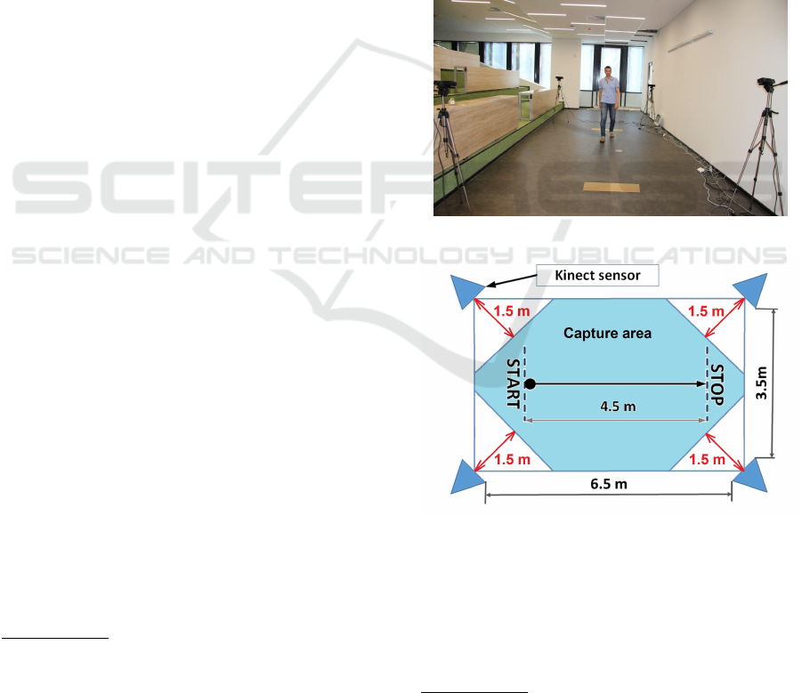
For human gait registration we use markerless opti-
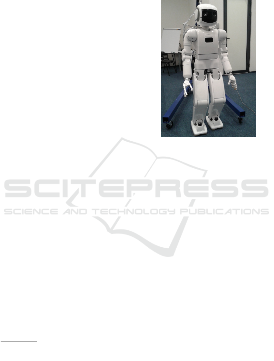
cal MoCap system based on four Kinect 2 sensors,
which encapsulate a total area of 23 sq.m with a walk-
ing area of 4.5 m length (Fig. 1, 2). Each Kinect
sensor contains RGB camera and depth sensor. Mo-
Cap system analyzes depth sensor video recordings
1
XSENS is an inertial 3D motion tracking technology
based on body-mounted MEMS inertial sensors and multi-
sensor data fusion algorithms, www.xsens.com
2
VICON is a passive optical motion capture technology
based on high resolution multi-camera system and advanced
real-time computer vision algorythms, www.vicon.com
to tracks human motion. Next, in order to reproduce
human locomotion with a human-like bipedal robot,
a human skeleton animation is built and a human 3D
model with linear and angular joint motion parame-
ters is reconstructed. MoCap system acquires human
motion data in three stages: 1) MoCap calibration; 2)
human motion tracking; 3) non-real-time processing
with iPi Soft software and MATLAB. These stages
were executed with iPi Soft which acquired MoCap
data and provided non-real-time processing by merg-
ing depth sensor video data from four Kinect sen-
sors, correcting the data and filtering out the noise.
Each Kinect sensor was connected to an individual
Windows PCs, forming a distributed system with one
master PC, which synchronized three other PCs and
the corresponding depth sensors’ records (Gabbasov
et al., 2015).
Figure 1: Kinect-based MoCap system: The scene view.
Figure 2: MoCap system: The scene configuration.
The detailed information on MoCap calibration,
measurement technique, data acquisition and process-
ing with iPi Soft could be found in (Gabbasov et al.,
2015) and iPi Docs resource
3
. The MoCap calibration
evaluates ground position and mutual Kinect sensor
localization. During calibration process we had sig-
3
iPi Docs: User Guide for Multiple Depth Sensors Con-
figuration, http://docs.ipisoft.com/User Guide for Multiple
Depth Sensors Configuration.
ZMP Trajectory from Human Body Locomotion Dynamics Evaluated by Kinect-based Motion Capture System
163
nificant issue with incorrect definition of a glowing
marker position by iPi Mocap Studio which were pos-
sibly caused by a weak contrast of the glowing marker
relatively to laboratory walls. We have overcome this
problem by performing the calibration in the dark
room. Unfortunately, such approach increased the av-
erage calibration error to 0.045 m (Gabbasov et al.,
2015), and thus decreased MoCap measurement ac-
curacy and also impacted the GCoM and ZMP errors.
In our further calculations of human GCoM and
ZMP trajectories we use the data which were obtained
from iPi Biomech Add-on plugin
4
, such as CoM co-
ordinates and accelerations. We exported biomechan-
ical characteristics into MATLAB and selected a time
period where a human walked forward, matching X -
axis with forward walking direction and Z-axis with
left-hand direction (on default, Y -axis is in upward di-
rection).
2.2 iPi Soft Package
iPi Soft software
5
uses 3D depth sensors to track
human joints and produce 3D animations, providing
human pose data with centimeter-level accuracy off-
line (Kim et al., 2015). It consists of free iPi Recorder
and iPi Mocap Studio software. iPi Recorder acquires
depth sensor video data from four Kinect 2 sensors,
and then iPi Mocap Studio processes multiple sen-
sor video records off-line, reconstructing 3D model
of human locomotion applying inverse kinematics ap-
proach. Afterwards we use iPi Biomech Add-on plu-
gin to calculate joint coordinates and angles, linear
and angular velocities, accelerations, and CoM posi-
tions over time.
Finally, we analyze human gait to identify key
features of human locomotion in MATLAB, collect-
ing statistically significant data to create an adequate
human gait mathematical model, which could be
adapted to AR-601M robot gait mathematical model.
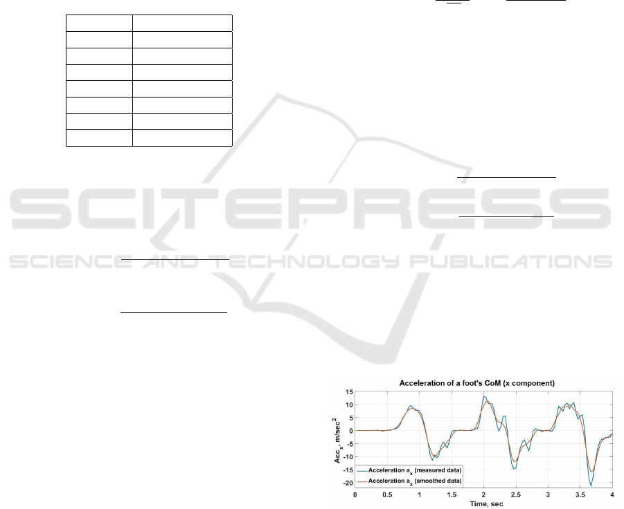
2.3 AR-601M Robot Description
The AR-601M biped robot
6
(Fig. 3) is a full-size hu-
manoid with the height of 144 cm and weight of 65
kg, having 43 active DoFs (including 12 DoFs in
robot legs). Nowadays, robot supports slow locomo-
tion with GCoM trajectory laying within support feet
during the its walking (Khusainov et al., 2016).
4
http://docs.ipisoft.com/iPi Biomech Add-on.
5
Motion Capture software, supporting markerless tech-
nology from Russian company iPi Soft, http://ipisoft.com
6
AR-601M robot is being developed by Russian
company Androidnaya Tehnika (Android Technics),
http://en.npo-at.com/products/ar-600
Figure 3: Android Technics AR-601M robot.
3 MOCAP-BASED HUMAN ZMP
CALCULATION
3.1 ZMP from Human Body Dynamics
as a Single Mass Point
The biped/human gait is statically stable when the
GCoM trajectory lays within a foot support area and
the corresponding support polygon (Goswami, 1999),
whereas criterion of dynamical stability is described
with zero moment point (ZMP) term (Vukobratovic
and Borovac, 2004). ZMP of a properly balanced gait
coincides with Center of Pressure (CoP), presenting a
point under the foot where the ground reaction force
fully reduces the effects of forces and moments on the
foot from the whole body (Vukobratovic and Borovac,
2004). ZMP is considered as the dynamical equiv-
alent of the GCoM: a body with the ZMP location
under the foot is stable, otherwise it is not.
To calculate ZMP from body dynamics as a single
mass point we used a rough approximation of biped
locomotion by a so-called cart-table model (Kajita
et al., 2003), which evaluates ZMP as a function of
CoM position and accelerations, anchoring the CoM
height ( ˆy) during locomotion:
(
x
zmp
(t) = x
com
(t) −
ˆy
g
¨x
com
(t)
z
zmp
(t) = z
com
(t) −
ˆy
g
¨z
com
(t)
(1)
where x
zmp
, z
zmp
are coordinates of ZMP. We applied
equation (1) to the data which were exported into
VISAPP 2016 - International Conference on Computer Vision Theory and Applications
164
MATLAB from iPi Biomech Add-on plugin.
3.2 ZMP from Human Body Dynamics
as Multiple Mass Points
We represent a human body as a model with a 12 mass
points m
i
set in the middle of the corresponding body
parts (a head, a torso, two shoulders, two forearms,
two thighs, two shins and two feet), and human mass
distribution for the body parts (Table 1) is performed
according to (Haley et al., 1988).
Table 1: Human mass distribution of the body parts (Haley
et al., 1988).
Segment Segment mass
Head 6%
Torso 48%
Shoulder 2.5%
Forearm 2.5%
Thigh 12%
Shin 4.5%
Foot 1.5%
The ZMP equations with multiple mass points via
inertia tensor in the sagittal and frontal planes are cal-
culated as follows (Ha and Choi, 2007):
x
zmp
(t) =
12
∑
i=1
m
i
( ¨y
i
+g)x
i
−
12
∑
i=1
m
i
¨x
i
y
i
12
∑
i=1
m
i
( ¨y
i
+g)
z
zmp
(t) =
12
∑
i=1
m
i
( ¨y
i
+g)z
i
−
12
∑
i=1
m
i
¨z
i
y
i
12
∑
i=1
m
i
( ¨y
i
+g)
(2)
where x
zmp
, z
zmp
are coordinates of ZMP and m
i
is the
point mass of the i-th body part.
3.3 CoM and ZMP Accuracy
Estimation Technique
Kinect-based MoCap brings a stochastic error to the
true measurement characteristics such as coordinates
and accelerations of the i-th body part (Gabbasov
et al., 2015) and therefore MoCap-measured values
should be treated as a non-stationary stochastic pro-
cess. We assume that the total measurement error
consists of several components: Kinect-based MoCap
calibration error (i.e. the error in cross-localization of
four Kinect sensors with regard to each other), the
accuracy of human motion approximation with iPi
Soft, the error in distance estimation between a hu-
man body and sensors, etc. Moreover, measurement
error analysis is a quite difficult task because it is im-
possible to take into account all Kinect sensor config-
urations and the accuracy of human motion approx-
imation with iPi Soft, which depends on the scene
background, human individual anatomical features,
clothes’ color, etc. Therefore, according to the Cen-
tral Limit Theorem we can assume that the measure-
ment errors are normally distributed and the variance
of the stochastic process is time-independent. Thus,
the probability density of the measured values (coor-
dinates and accelerations of the i-th body part’s CoM)
is defined as:
p(x, t) =
1
√
2πσ
exp−
(x −µ(t))
2
2σ
2
(3)
where x is a measured value, µ(t) is a time-dependent
mathematical expectation (e.g., a true coordinates or
accelerations for a body part’s CoM), σ is a variance
of the measured value.
In our study, the absolute measurement error could
be estimated as a standard deviation from the time-
dependent mean. For example, the measurement error
of x-coordinate of CoM is computed as the unbiased
standard deviation:
∆x
com
=
v
u
u
u
t
N
∑
i=1
(x
i
−M(x, t))
2
(N −1)
(4)
where M(x, t) is mathematical expectation for x-
coordinate of CoM. The mathematical expectation
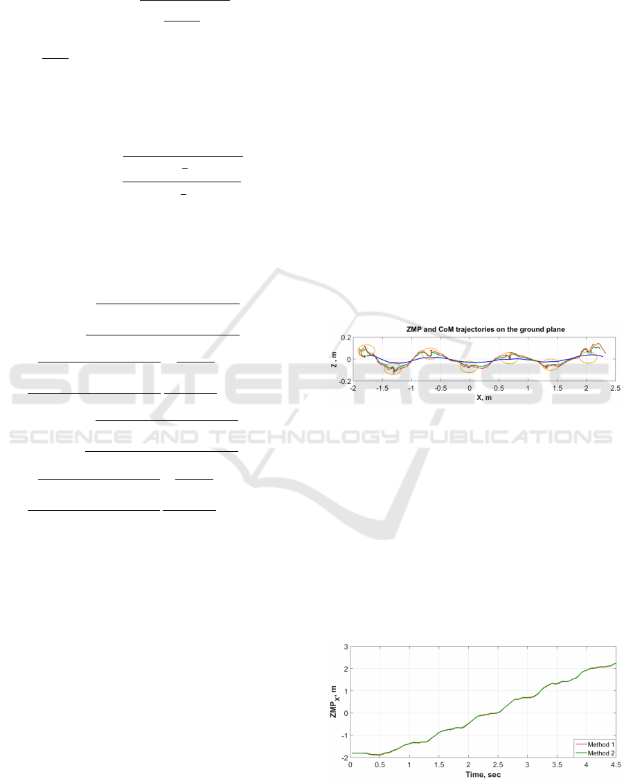
of CoM for i-th body part changes over time along
x-coordinate during human locomotion (e.g., foot’s
CoM acceleration is shown in Fig. 4, blue curve).
Therefore we smooth the MoCap-measured data (blue
curve in Fig. 4) with moving average to estimate the
mathematical expectation (brown curve in Fig. 4).
Figure 4: Measured foot’s CoM acceleration along the x-
axis (blue curve) and its smoothing (brown curve).
We use the same method to calculate the smoothed
mathematical expectation of CoM acceleration and
coordinates for both human body as a single mass
point (the first method, Section 3.1) and all body parts
as multiple mass points (the second method, Sec-
tion 3.2). As far as we provide indirect ZMP measure-
ZMP Trajectory from Human Body Locomotion Dynamics Evaluated by Kinect-based Motion Capture System
165
ments, the Error Theory should be applied to calculate
ZMP measurement error ∆ZMP
x
with equation:
∆ZMP
x
=
s
(
n
∑
i=1
∂ZMP
∂x
i
dx
i
)
2
(5)
where
∂ZMP
∂x
i
is a partial derivative of ZMP function
for one of the variables and dx
i
is the estimation of
absolute measurement error for this variable.
Therefore, the total ZMP error for the first method
is calculated as follows:
∆ZMP
x
=
q
(∆x
2
com
+ (
ˆy
g
∆a
xcom
)
2
)
∆ZMP
z
=
q
(∆z
2
com
+ (
ˆy
g
∆a
zcom
)
2
)
(6)
where ˆy is average CoM position along the vertical
Y -axis.
Whereas the total ZMP error for the second
method is calculated as follows:
∆ZMP
x
=
s
12
∑
i=1
(m
i
( ¨y
i
+g)∆x
i
)
2
+
12
∑
i=1
(m
i
x
i
∆ ¨y
i
)
2
12
∑
i=1
m
i
( ¨y
i
+g)x
i
−
12
∑
i=1
m
i
¨x
i
y
i
+
s
12
∑
i=1
(m
i
y
i
∆ ¨x
i
)
2
+
12
∑
i=1
(m
i
¨x
i
∆y
i
)
2
12
∑
i=1
m
i
( ¨y
i
+g)x
i
−
12
∑
i=1
m
i
¨x
i
y
i
s
12
∑
i=1
m
i
∆y
i
12
∑
i=1
m
i
( ¨y
i
+g)
∆ZMP
z
=
s
12
∑
i=1
(m
i
( ¨y
i
+g)∆z
i
)
2
+
12
∑
i=1
(m
i
z
i
∆ ¨y
i
)
2
12
∑
i=1
m
i
( ¨y
i
+g)z
i
−
12
∑
i=1
m
i
¨z
i
y
i
+
s
12
∑
i=1
(m
i
y
i
∆ ¨z
i
)
2
+
12
∑
i=1
(m
i
¨z
i
∆y
i
)
2
12
∑
i=1
m
i
( ¨y
i
+g)z
i
−
12
∑
i=1
m
i
¨z
i
y
i
s
12
∑
i=1
m
i
∆y
i
12
∑
i=1
m
i
( ¨y
i
+g)
(7)
where x
i
, y
i
, z
i
, ¨x
i
, ¨y
i
, ¨z
i
correspond to the coordi-
nates and accelerations of the i-th body part, and
∆x
i
, ∆y
i
, ∆z
i
, ∆ ¨x
i
, ∆ ¨y
i
, ∆ ¨z
i
are absolute error estima-
tions for coordinates and accelerations of the i-th
body part.
4 ZMP TRAJECTORY AND
ACCURACY ANALYSIS
4.1 ZMP and GCoM Trajectories from
Human Body Dynamics
ZMP and GCoM trajectories on the ground plane
were calculated from human body data, where hu-
man body was approximated a single and multiple
mass points methods, according to equations (1) and
(2) correspondingly. Figure 5 represents human ZMP
trajectories obtained by a single mass point method
(red curve) and multiple mass points method (green
curve), whereas blue curve shows the GCoM trajec-
tory and orange ellipses illustrate human footprints.
The figure shows that both ZMP and GCoM trajec-
tories are located close to the footprints (and conse-
quently to the corresponding support polygons). It
satisfies the static (GCoM) and dynamic (ZMP) sta-
bility criteria (Mrozowski et al., 2007) and proves
that the human gait was properly balanced. More-
over, the ZMP trajectory which was calculated apply-
ing multiple mass point method lays slightly closer to
the GCoM trajectory than the calculated with a single
mass point method trajectory. As far as both methods
process the same MoCap data, it means that they have
different accuracy. Only the last segment of ZMP tra-
jectories lays outside the support area (footprint) at
the coordinate of 2 m. It emphasizes the balancing
changes before a human stop at the end of MoCap
walking area.
Figure 5: Human ZMP trajectory from single mass point
(red curve) and multiple mass points methods (green curve),
GCoM trajectory (blue curve) and footprints (orange el-
lipses) on the ground plane. The X-axis and Z-axis are ori-
ented in the human walking and orthogonal to the walking
(lateral) directions respectively.
Figures 6 and 7 show ZMP trajectories vs. time in
sagittal and frontal planes respectively which are cal-
culated from human body locomotion dynamics. The
significant deviations of ZMP trajectory in the frontal
plane in the vicinity of the footprint positions arise
from the limitations of MoCap system measurement
accuracy.
Figure 6: Human ZMP trajectory vs. time in sagittal plane
for single mass point (red curve) and multiple mass points
methods (green curve).
VISAPP 2016 - International Conference on Computer Vision Theory and Applications
166
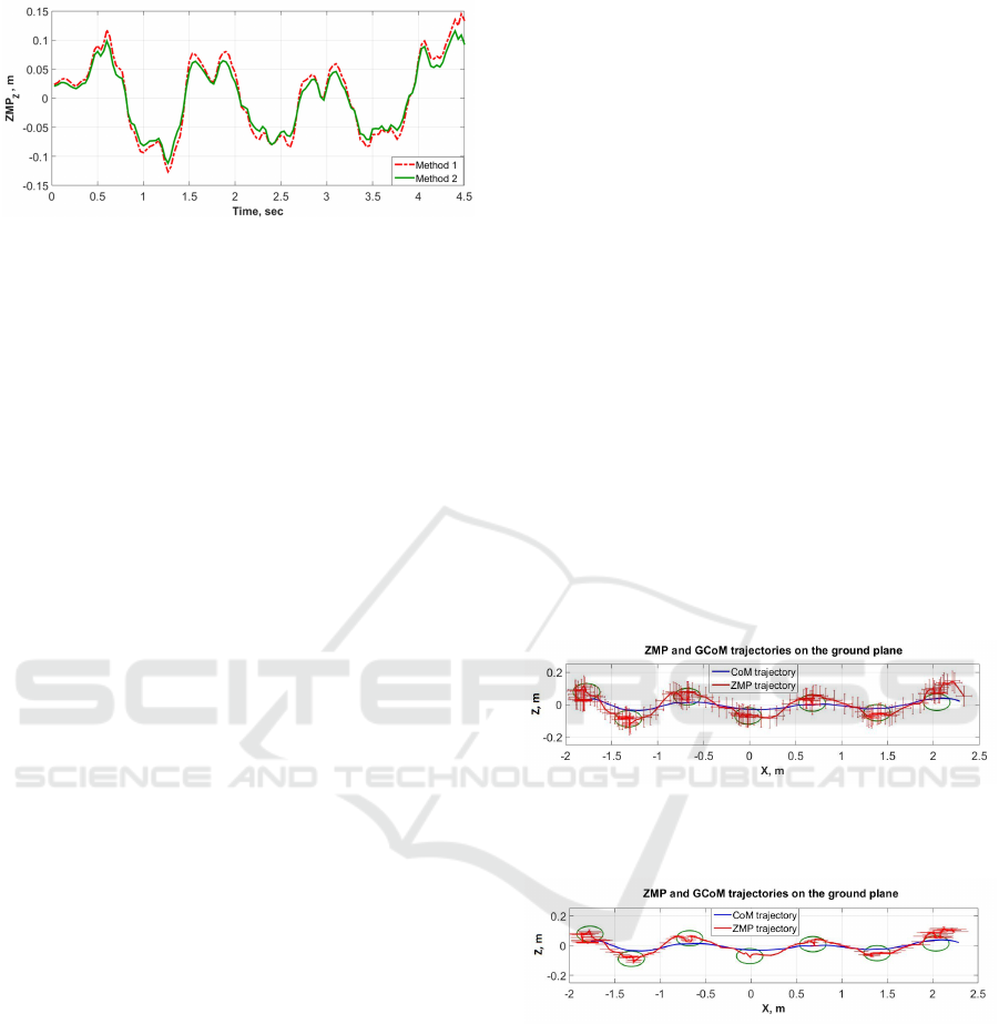
Figure 7: Human ZMP trajectory vs. time in frontal plane
for single mass point (red curve) and multiple mass points
methods (green curve).
4.2 CoM and ZMP Accuracy
Estimation
We estimated the GCoM measurement error as a stan-
dard deviation applying equation (4), which gave us
the typical values:
(
∆x
com
≈ 1cm
∆z
com
≈ 1cm
(8)
For the human body model which is built with a sin-
gle mass point method the total ZMP errors are time-
independent due to the model simplicity (Gabbasov
et al., 2015), and its values are computed according to
equations (6):
(
∆ZMP
x
≈ 7cm
∆ZMP
z
≈ 7cm
(9)
For the 12 mass points human body model the to-
tal ZMP errors were calculated according to equa-
tions (7). The calculated values of the total ZMP er-
ror in the walking direction ∆ZMP
x
varies from 1 mm
to 35 mm (where the value ∆ZMP
x
= 35 mm corre-
sponds to the MoCap walking area of 2 m length, i.e.
±1 m from the center of MoCap scene in Fig. 2),
whereas ZMP error in lateral direction ∆ZMP
z
varies
in the range from 1 to 7 mm.
(
∆ZMP
x
≈ 3.5cm
∆ZMP
z
≈ 0.7cm
(10)
Moreover, the ZMP error in the walking direction
∆ZMP
x
strongly depends on the x-coordinate of ZMP
trajectory (i.e., on a human position relatively to the
center of Kinect-based MoCap system), which results
in the minimal total ZMP error at the center of Mo-
Cap walking area and maximal error on the bound-
aries of the MoCap capture zone. The growth of
∆ZMP
x
is nonlinear from MoCap capture zone center
to its boundaries. While ∆ZMP
x
was approximately
the same for both ZMP evaluation methods on the
boundaries of the ±1.5 m interval of the MoCap cap-
ture zone (centered in the middle of the 4.5 m walking
zone), for the MoCap capture zone of 4.5 m (which
corresponds to start and stop lines in Fig. 2) the sec-
ond ZMP evaluation method (Section 3.2) gives much
higher total ZMP error ∆ZMP
x
than the first method
(Section 3.1). Therefore, to eliminate the influence of
acceleration and deceleration within the first steps and
thus to minimize the total ZMP error we restricted the
MoCap active capture zone to ±1 m from the center
of the MoCap scene for the second method.
Figures 8 and 9 demonstrate ZMP and GCoM tra-
jectories for the single and multiple mass point meth-
ods of human body correspondingly. The total ZMP
error is shown with the red bars. The comparison of
total ZMP errors for human body models as a sin-
gle and multiple mass points (equations (9) and (10)
correspondingly) demonstrates that the multiple mass
point method is more accurate for the shortened Mo-
Cap capture zone of 2 m length and could be better
applicable to the task of human locomotion analysis
by static (GCoM) and dynamic (ZMP) stability crite-
ria of human gait balance.
Figure 8: ZMP trajectory (red curve) and the total ZMP er-
rors (red bars), calculated with a single mass point method,
and GCoM trajectory (blue curve).
Figure 9: ZMP trajectory (red curve) and the total ZMP
errors (red bars), calculated with a multiple mass points
method, and GCoM trajectory (blue curve).
5 CONCLUSION AND FUTURE
WORK
This paper focused on the analysis of human loco-
motion. The locomotion data was recorded with Mo-
Cap markerless tracking and visualization technol-
ogy, which is based on four Kinect 2 sensors and
non-real-time processing with iPi Soft software and
ZMP Trajectory from Human Body Locomotion Dynamics Evaluated by Kinect-based Motion Capture System
167

MATLAB. Human gait balance was analyzed apply-
ing static (GCOM) and dynamic (ZMP) stabilities.
Human ZMP and GCoM trajectories were calcu-
lated by two methods, which consider human body
as a simplified approximation with the models of a
single mass point and multiple mass points. Our cal-
culations demonstrated close localization of analyzed
GCoM and ZMP trajectories to the human’s footprints
and the corresponding support polygons. It means
that the human walking had static and dynamic sta-
bility, proving that the human gait was properly bal-
anced. The comparison of total ZMP errors for hu-
man body models as a single and multiple mass points
demonstrated that the later method is significantly
more accurate for the limited MoCap walking zone of
2 m length (the maximal ZMP error was 3.5 cm along
the walking direction and 0.7 cm in lateral direction)
than the former one, and thus should be preferred for
human gait estimation. Quite significant ZMP trajec-
tory deviations in the vicinity of footprints’ positions
arise from the limitations of MoCap system measure-
ment accuracy.
Finally, we use MoCap system and analyze human
locomotion to identify key features of human walk-
ing, collecting statistically significant data to create
an adequate human gait mathematical model, which
could be adapted to Russian AR-601M robot simu-
lation model, yielding its statically and dynamically
stable and more natural locomotion.
ACKNOWLEDGEMENTS
This work was supported by Russian Ministry of
Education and Science, and our industrial partner
Android Technics under Scientific and Technolog-
ical Research and Development Program of Rus-
sian Federation for 2014-2020 years (research grant
RFMEFI60914X0004). Special thanks to iPi Soft
company for providing temporary access to iPi Soft
Mocap Studio.
REFERENCES
Asano, F. and Luo, Z.-W. (2008). Energy-efficient and
high-speed dynamic biped locomotion based on prin-
ciple of parametric excitation. IEEE Transactions on
Robotics, 24(6):1289–1301.
Chalodhorn, R., Grimes, D. B., Grochow, K., and Rao, R.
P. N. (2007). Learning to walk through imitation. In
Proc. of 20th Int. Joint Conference on Artifical Intel-
ligence, IJCAI’07, pages 2084–2090, San Francisco,
CA, USA. Morgan Kaufmann Publishers Inc.
Dasgupta, A. and Nakamura, Y. (1999). Making feasible
walking motion of humanoid robots from human mo-
tion capture data. In IEEE ICRA, volume 2, pages
1044–1049.
Field, M., Stirling, D., Naghdy, F., and Pan, Z. (2009). Mo-
tion capture in robotics review. In IEEE Int. Conf. on
Control and Automation, pages 1697–1702.
Gabbasov, B., Danilov, I., Afanasyev, I., and Magid, E.
(2015). Toward a human-like biped robot gait: Biome-
chanical analysis of human locomotion recorded by
kinect-based motion capture system. In Proc. of 10th
Int. Symposium on Mechatronics and its Applications.
Goswami, A. (1999). Foot rotation indicator (fri) point: A
new gait planning tool to evaluate postural stability of
biped robots. In IEEE ICRA, pages 47–52.
Ha, T. and Choi, C.-H. (2007). An effective trajectory gen-
eration method for bipedal walking. Robotics and Au-
tonomous Systems, 55(10):795–810.
Haley, J. et al. (1988). Anthropometry and mass distribu-
tion for human analogues. In Military Male Aviators,
Volume 1, Aerospace Medical Research Lab., Wright-
Patterson AFB Ohio USA, Tech. Rep, pages 34–38.
Kajita, S., Kanehiro, F., Kaneko, K., Fujiwara, K., Harada,
K., Yokoi, K., and Hirukawa, H. (2003). Biped walk-
ing pattern generation by using preview control of
zero-moment point. In IEEE ICRA, volume 2, pages
1620–1626.
Khusainov, R., Afanasyev, I., and Magid, E. (2016). An-
thropomorphic robot modelling with virtual height in-
verted pendulum approach in Simulink: step length
and robot height influence on walking stability. In Int.
Conf. on Artificial ALife and Robotics (in press).
Kim, H., Lee, S., Lee, D., Choi, S., Ju, J., and Myung, H.
(2015). Real-time human pose estimation and gesture
recognition from depth images using superpixels and
svm classifier. Sensors, 15(6):12410–12427.
Larsen, J. C. and Stoy, K. (2011). Energy efficiency of robot
locomotion increases proportional to weight. Proce-
dia Computer Science, Proc. 2nd European Future
Technologies Conference and Exhibition, 7:228 – 230.
Mrozowski, J., Awrejcewicz, J., and Bamberski, P. (2007).
Analysis of stability of the human gait. Journal of
theoretical and applied mechanics, 45:91–98.
Naksuk, N., Lee, C., and Rietdyk, S. (2005). Whole-body
human-to-humanoid motion transfer. In 5th IEEE-
RAS Int. Conf. on Humanoid Robots, pages 104–109.
Sinnet, R. W., Powell, M. J., Jiang, S., and Ames, A. D.
(2011). Compass gait revisited: A human data per-
spective with extensions to three dimensions. In Proc.
of 50th IEEE Conf. on Decision and Control, and Eu-
ropean Control Conf. (CDC-ECC), pages 682–689.
Vukobratovic, M. and Borovac, B. (2004). Zero-moment
point thirty five years of its life. International Journal
of Humanoid Robotics, 1(1):157–173.
Vukobratovic, M. and Juricic, D. (1969). Contribution to
the synthesis of biped gait. In IEEE Transactions on
Biomedical Engineering, volume 16(1), pages 1–6.
Wong, C., Zhang, Z.-Q., Lo, B., and Yang, G.-Z. (2015).
Wearable sensing for solid biomechanics: A review.
Sensors Journal, IEEE, 15(5):2747–2760.
VISAPP 2016 - International Conference on Computer Vision Theory and Applications
168
