
Characteristics of Phase-Shifted Fiber Bragg Grating Inscribed by
Fusion Splicing Technique and Femtosecond Laser
Yajun Jiang
1,2
, Jian Xu
1,2
, Yuan Yuan
1,2
, Dexing Yang
1,2
, Dong Li
1,2
, Meirong Wang
1,2
and Jianlin Zhao
1,2
1
Key Laboratory of Space Applied Physics and Chemistry, Ministry of Education, Xi’ an, China
2
Shaanxi Key Laboratory of Optical Information Technology, School of Science, Northwestern Polytechnical University
Xi’ an 710072, China
Keywords: Optical Fiber Sensors, Phase-shifted Fiber Bragg Gratings, Femtosecond Laser.
Abstract: Phase-shifted fiber Bragg grating (PS-FBG) inscription in nonphotosensitive single mode fiber (SMF) by
the fusion splicing technique and femtosecond laser is reported. Two SMFs are fusion spliced to introduce a
refractive index modulation point which acts as a phase shift, then exposing the fusion spliced fiber with
femtosecond laser and a uniform phase mask. Two dips can be observed in the transmission spectrum of
inscribed grating, and the max induced refractive index modulation can reach to 4.210
-4
without any fiber
sensitization for a peak power density of 4.510
13
W/cm
2
. The annealing tests show that type I PS-FBG is
successfully inscribed. This type of grating also shows good strain and pressure characteristics. Such PS-
FBGs can be potentially used for optical fiber lasers, filters and sensors.
1 INTRODUCTION
Phase-shifted fiber Bragg gratings (PS-FBGs) show
a very narrow transmission band within its reflection
spectrum, and they have found many applications in
wavelength-division multiplexing systems (Agrawal
and Radic, 1994), optical fiber lasers (Chen et al.,
2005), high finesse transmission filters (Zou et al.,
2013), ultrasonic detectors (Rosenthal et al., 2011;
Liu and Ham, 2012) and optical fiber sensors
(Malara et al., 2015). Many methods have been
presented for PS-FBG inscription, such as
employing a phase-shifted phase mask (PM) (Liu
and Ham, 2012), Moiré method by slightly tuning
the laser wavelength (Malara et al., 2015) or shifting
the fiber perpendicularly to the fiber axis (Reid et al.,
1990), moving fiber-scanning beam technique (Cole
et al., 1995), post-processing technique by exposing
the uniform FBG with focused UV (Canning and
Sceats, 1994) or CO
2
laser (Xia et al., 2005), and
exposing twice process (Chehura et al., 2010), in
which two uniform FBGs with same parameters are
overlapped physically by one grating period. These
methods mentioned above possess good repeatability,
flexibility and quality, but they need the relatively
expensive phase-shifted PM or a high precise control
or the PS-FBGs show poor annealing properties.
In the past decades, femtosecond laser has been
explored for writing complex FBGs in many types
of fibers (Thomas et al., 2008; Marshall et al., 2010;
Williams et al., 2011). PS-FBG has been inscribed
by point-by-point technique with femtosecond laser
by modulating the phase and frequency of
femtosecond laser with two triggers (Marshall et al.,
2010) or an electro-optical modulator (Burgmeier et
al., 2014) in conjunction with a high precise stage,
this technique is versatile and repeatable; however, it
requires the synchronization of pulse train with the
writing position. The PS-FBG has be also inscribed
by introducing an in-grating bubble in the middle of
uniform FBG with femtosecond laser and fusion
splicing technique (Liao et al., 2013), in which the
phase shift is adjusted by filling liquids with
different refractive indices into the bubble, whereas
the fabrication process is complex. Another PS-FBG
inscription technique is proposed by overexposing a
uniform FBG with femtosecond laser and a uniform
PM (He et al., 2015), which is easy to implement,
but an obvious decrease in the transmission loss at
the Bragg wavelength is observed during the
inscription process.
In this paper, a new method for PS-FBG
inscription in nonphotosensitive single mode fiber
358
Jiang, Y., Xu, J., Yuan, Y., Yang, D., Li, D., Wang, M. and Zhao, J.
Characteristics of Phase-Shifted Fiber Bragg Grating Inscribed by Fusion Splicing Technique and Femtosecond Laser.
DOI: 10.5220/0005738503560360
In Proceedings of the 4th International Conference on Photonics, Optics and Laser Technology (PHOTOPTICS 2016), pages 358-362
ISBN: 978-989-758-174-8
Copyright
c
2016 by SCITEPRESS – Science and Technology Publications, Lda. All rights reserved

(SMF) by fusion splicing technique and
femtosecond laser is reported. The PS-FBG is
inscribed by fusion splicing two SMFs and then
exposing the fusion spliced fiber with femtosecond
laser and a uniform PM. Its annealing, strain and
pressure characteristics are experimentally studied.
2 EXPERIMENTAL SETUP
The inscription process is divided into three steps.
First, the SMF (Coring SMF-28e+) is cleaved into
two sections by using an optical fiber cleaver after
stripping its coating with a length of about 20 mm.
Then the two sections are spliced by a fusion splicer,
and the typical fusion loss is 0.01 dB. Finally, the
fusion spliced fiber is exposed by femtosecond laser
through a cylindrical lens and a uniform PM. Figure
1 shows the schematic diagram of the PS-FBG
inscription by femtosecond laser. The femtosecond
laser pulses have a 35 fs duration and are generated
by a Ti:sapphire amplifier at wavelength of 800 nm
with pulse repetition rate of 1 kHz. The max output
pulse energy of 4 mJ can be adjusted by rotating a
half-wave plate followed by a polarizer. The laser
beam has a radius of 4 mm and is focused by the
cylindrical lens with focal length of 40 mm through
a zero-order nulled PM onto the fiber. The half-
width of the focal line
is 2.5 m according to
=
f/(
0
)
,
where
is the wavelength, f is the focal
length of the cylindrical lens, and
0
is the incident
beam radius. The coating stripped SMF is cleaved
and spliced, and then it is positioned behind the PM
at a distance of about 2 mm in order to produce two-
pure interference (Smelser et al., 2004). The PM is
designed for 800 nm radiation with a period of 2142
nm (Ibsen Photonics) which is twice of the period of
inscribed PS-FBG. Less than 5% of the beam is
diffracted into the 0th order, and more than 70% of
the beam is diffracted into the 1st orders. The
Figure 1: Schematic diagram of the PS-FBG inscription by
femtosecond laser.
during the inscription process by an ASE source and
an optical spectrum analyzer.
3 RESULTS AND DISCUSSIONS
The fusion spliced fiber is exposed by 600 J laser
pulses for 100 s and the peak power density at the
focus is about 4.110
13
W/cm
2
. Figure 2 gives the
reflection and transmission spectra of the induced
PS-FBG. We can see that there are two main dips in
the transmission spectrum because the PS-FBG is
successfully inscribed. A refractive index
modulation point is introduced by fusion splicing
two SMFs in the fiber core, which acts as a phase
shift during the inscription process. The 2nd order
PS-FBG is inscribed according to the Bragg
condition defined by m
Bragg
=2n
eff
g
, where
Bragg
is
the Bragg wavelength, m is the order number, n
eff
represents the effective index of fiber core, and
g
donates the grating period. The measured Bragg
wavelength
Bragg
=1548.1 nm, so the calculated
n
eff
=1.445. The phase shift is observed during the
whole inscription process which is different from the
PS-FBG formation in stage II (He et al., 2015), and
it is almost unchanged. The cladding modes are also
observed due to the light coupling into the fiber
cladding, which can be suppressed by scanning the
inscription laser beam vertically to maximize
coverage of the fiber core region.
1544 1546 1548 1550 1552
-70
-60
-50
-40
-30
-20
Wavelength (nm)
Reflection (dBm)
-40
-35
-30
-25
Transmission (dBm)
Figure 2: Reflection and transmission spectra of the PS-
FBG inscribed by femtosecond laser.
During the inscription process, the wavelengths
show a nonlinear red shift for about 0.14 nm with
the exposure time (total incident laser fluence). The
transmission losses of the 1st and 2nd dips increase
to -9.3 dB and -4.8 dB, while the wavelengths shift
to 1548.20 nm and 1547.94 nm, respectively. No
obvious saturation is observed within 100 s. The
induced refractive index modulation can be inferred
from the expression for maximum reflectivity
Femtosecond laser
0 order
+1 order -1 order
PM
SMF
g
m
+2 order
-2 order
Characteristics of Phase-Shifted Fiber Bragg Grating Inscribed by Fusion Splicing Technique and Femtosecond Laser
359
R=tanh
2
(
L), where the coupling coefficient
=mn
m
/(2n
eff
m
), L is the grating length, n
m
is
the refractive index modulation of the mth order
grating, and
m
is the PM period. So the induced
refractive index modulation n
m
=3.310
-4
for a dip
of -9.3 dB. The fiber core’s refractive index n
eff
at
the fusion spliced point decreases within few
hundreds of micronmeters due to dopant diffusion,
glass structure change and residual stress relaxation
(Abrishamian et al., 2012), so negative refractive
index change in the fusion spliced point is
introduced to form a PS-FBG during the inscription
process. The insertion loss at 1550 nm is about 0.3
dB.
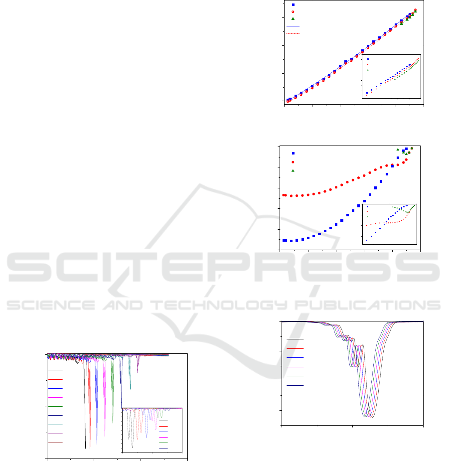
The annealing tests are conducted in a tube
furnace. The evolution of the transmission spectra of
PS-FBG form 24
°
C to 940
°
C are shown in Fig. 3. It
can be seen that the transmission spectrum of PS-
FBG shifts to long wavelength, at the same time, it
transmission decreases with increase the
temperature. The change of the central wavelengths
and the transmission losses with the temperature are
given in Fig 4 (a) and (b), respectively. It can be
seen that the central wavelengths of the two dips
shift almost with the same speed according to the
polynomial fit results. But the transmission loss of
the 2nd dip changes slowly compared with the 1st
dip. There is a turning point near the temperature of
800
°
C at which the loss of the 2nd dip is larger than
the 1st one. At the same time a new third dip can be
observed, its loss increases firstly and approaches to
the 2nd one at the temperature of 920
°
C, and then
they decrease at the same speed. The experimental
results show that type I PS-FBG has been inscribed.
Figure 3: Evolution of the transmission spectra of PS-FBG
under different temperature.
The hydrostatic pressure test of the PS-FBG was
performed in a sealed stainless steel tube filled with
water. The transmission loss of the PS-FBG is about
-13 dB, so the induced refractive index modulation
n
m
=4.210
-4
. Figure 5 gives the evolution of the
transmission spectra of PS-FBG under different
pressures in the range from 0 MPa to 25 MPa with a
step of 5 MPa. It can be seen that the transmission
Figure 4: Change of the (a) central wavelengths and (b)
transmission losses for two dips with the temperature.
1547 1548 1549
-12
-8
-4
0
Transmission (dB)
Wavelength (nm)
0 MPa
5 MPa
10 MPa
15 MPa
20 MPa
25 MPa
Figure 5: Evolution of the transmission spectra of PS-FBG
under different pressures.
spectrum has a blue shift and its shape is not
distorted during increasing the pressure. Figure 6
depicts the central wavelengths and transmission
losses for the two dips under different pressures.
From Fig. 6 (a), we can see that the central
wavelengths for two dips decrease linearly with the
pressure at a same sensitivity of -4.4 pm/MPa, which
is slightly higher than that of the UV laser induced
0 200 400 600 800 1000
-10
-8
-6
-4
-2
0
1st dip
2nd dip
3rd dip
Transmission (dB)
Temperature (
0
C)
(b)
700 750 800 850 900 950
-3
-2
-1
0
1st dip
2nd dip
3rd dip
700 750 800 850 900 950
1558
1559
1560
1561
1st dip
2nd dip
3rd dip
0 200 400 600 800 1000
1548
1552
1556
1560
1st dip
2nd dip
3rd dip
Polynomial fit of the 1st dip
Polynomial fit of the 2nd dip
Wavelength (nm)
Temperature (
0
C)
Y1=2.5*E-6X1^2+0.012*X1+1547.73
Y2=2.6*E-6X2^2+0.012*X2+1547.48
(a)
1558 1560 1562
-2.5
-2.0
-1.5
-1.0
-0.5
0.0
780
0
C
820
0
C
860
0
C
900
o
C
920
o
C
940
o
C
1540 1550 1560 1570
-10
-5
0
Transmission (dB)
Wavelength (nm)
24
0
C
120
0
C
240
0
C
360
0
C
480
0
C
600
0
C
720
0
C
840
0
C
940
0
C
OSENS 2016 - Special Session on Optical Sensors
360
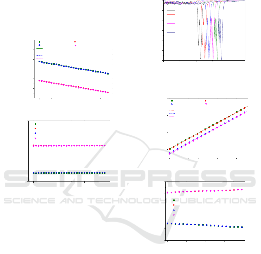
FBG in standard SMF. There is no hysteresis for
both increasing and decreasing cycles. In Fig. 6 (b),
the transmission losses of the two dips are almost
unchanged under different pressures, and the
fluctuation is only about 0.1 dB.
0 10 20 30
1547.9
1548.0
1548.1
1548.2
1548.3
1548.4
1548.5
Increase of the 1st dip Increase of the 2nd dip
Decrease of the 1st dip Decrease of the 2nd dip
Linear fit of increase of the 1st dip
Linear fit of increase of the 2nd dip
Linear fit of decrease of the 1st dip
Linear fit of decrease of the 2nd dip
Wavelength (nm)
Pressure (MPa)
The 1st dip
Increase: Y1=1548.279-0.0044*X1
Decrease: Y2=1548.277-0.0044*X2
The 2st dip
Increase: Y3=1548.082-0.0044*X3
Decrease: Y4=1548.082-0.0044*X4
(a)
0 10 20 30
-15
-10
-5
0
Increase of the 1st dip
Increase of the 2nd dip
Decrease of the 1st dip
Decrease of the 2nd dip
Transmission (dB)
Pressure (MPa)
(b)
Figure 6: Changes of the (a) central wavelengths and (b)
transmission losses for two dips under different pressures.
The strain test of another PS-FBG with the dip of
-11.6 dB inscribed under the same condition was
performed by fixing it on two manual translating
stages with a resolution of 0.01 mm, and the space
between the two fixed points was 483 mm. The
strain was applied on the FBG by adjusting one of
the translating stages up to 1 mm with a step of 0.05
mm. Figure 7 shows the evolution of the
transmission spectra under different strains in the
range from 0 to 2070 . We can see that the
transmission spectrum has a red shift and there is no
distortion during increasing the strain. Figure 8 (a)
and (b) depict the wavelengths shift for two dips
under different strains. We can see that the strain
response of the PS-FBG shows good linearity and
repeatability, and the strain sensitivity is 1.2 pm/,
which is the same with that of the UV laser induced
FBG. But the transmission loss of the 1st dip
decreases when increasing the strain, while it
increases for the 2nd one.
1544 1548 1552
-12
-10
-8
-6
-4
-2
0
Transmission (dB)
Wavelength (nm)
0
414
828
1242
1656
2070
Figure 7: Evolution of the transmission spectra under
different strains.
0 500 1000 1500 2000
1548
1549
1550
1551
Increase of the 1st dip Increase of the 2nd dip
Decrease of the 1st dip Decrease of the 2nd dip
Linear fit of increase of the 1st dip
Linear fit of decrease of the 1st dip
Linear fit of increase of the 2nd dip
Linear fit of decrease of the 2nd dip
Wavelength (nm)
Strain ()
The 1st dip
Increase:Y1=1548.551+0.0012*X1
Decrease:Y2=1548.515+0.0012*X2
The 2nd dip
Increase:Y3=1548.278+0.0012*X3
Decrease:Y4=1548.243+0.0012*X4
(a)
0 500 1000 1500 2000
-13
-12
-11
-10
-9
-8
Increase of the 1st dip
Increase of the 2nd dip
Decrease of the 1st dip
Decrease of the 2nd dip
Transmission (dB)
Strain ()
(b)
Figure 8: Change of the (a) central wavelengths and (b)
transmission losses for two dips under different strains.
4 CONCLUSIONS
In conclusion, PS-FBGs have been successfully
inscribed in nonphotosensitive SMFs by fusion
splicing technique and femtosecond laser through a
uniform PM. Two main dips can be observed due to
the formation of PS-FBG and its transmission
spectrum of PS-FBG shows a nonlinear red shift
during the inscription process. The max induced
refractive index modulation of 4.210
-4
is achieved
for a PS-FBG with a dip of -13 dB for a peak power
Characteristics of Phase-Shifted Fiber Bragg Grating Inscribed by Fusion Splicing Technique and Femtosecond Laser
361

density of 4.510
13
W/cm
2
. The annealing, strain
and pressure characteristics of the PS-FBG are
experimentally studied. These PS-FBGs inscribed in
SMFs by femtosecond laser will find applications in
optical fiber lasers, two wavelength filters and
optical fiber sensors.
ACKNOWLEDGEMENTS
This work was supported by the National Natural
Science Foundation of China (Grant No. 61405163),
the Fundamental Research Funds for the Central
Universities (Grants No. 3102014KYJD025,
3102014JCQ01100 and 3102015BJ(Ⅱ)ZS015) and
the Northwestern Polytechnical University
Foundation for Fundamental Research (Grant No.
JC20110272).
REFERENCES
Agrawal, G & Radic, S 1994, ‘Phase-shifted fiber Bragg
gratings and their application for wavelength
demultiplexing’, IEEE Photonics Technology Letters,
vol. 6, no. 8, pp. 995-997.
Chen, X, Yao, J & Deng, Z 2005, ‘Ultranarrow dual-
transmission-band fiber Bragg grating filter and its
application in a dual-wavelength single-longitudinal-
mode fiber ring laser’, Optics Letters, vol. 30, no. 16,
pp. 2068-2070.
Zou, X, Li, M, Pan, W, Yan, L, Azaña, J & Yao, J 2013,
‘All-fiber optical filter with an ultranarrow and
rectangular spectral response’, Optics Letters, vol. 38,
no. 16, pp. 3096-3098.
Rosenthal, A, Razansky, D & Ntziachristos, V 2011,
‘High-sensitivity compact ultrasonic detector based on
a -phase-shifted fiber Bragg grating’, Optics Letters,
vol. 36, no. 10, pp. 1833-1835.
Liu, T & Han, M 2012, ‘Analysis of -phase-shifted fiber
Bragg gratings for ultrasonic detection’, IEEE Sensors
Journal, vol. 12, no. 7, pp. 2368-2373.
Malara, P, Campanella, C, De Leonardis, F, Giorgini, A,
Avino, S, Passaro, V & Gagliardi, G 2015, ‘Enhanced
spectral response of pi-phase shifted fiber Bragg
gratings in closed-loop configuration’, Optics Letters,
vol. 40, no. 9, pp. 2124-2126.
Reid, D, Ragdale, C, Bennion, I, Buus, J & Stewart, W
1990, ‘Phase-shifted Moiré grating fibre resonators’,
Electronics Letters, vol. 26, no. 1, pp. 10-12.
Cole, M, Loh, W, Laming, R, Zervas, M & Barcelos, S
1995, ‘Moving fibre/phase mask-scanning beam
technique for enhanced flexibility in producing fibre
gratings with uniform phase mask’, Electronics
Letters, vol. 31, no. 17, pp. 1488-1490.
Canning, J & Sceats, M 1994, ‘π-phase-shifted periodic
distributed structures in optical fibres by UV post-
processing’, Electronics Letters, vol. 30, no. 16, pp.
1344-1345.
Xia, L, Shum, P & Lu, C 2005, ‘Phase-shifted bandpass
filter fabrication through CO
2
laser irradiation’, Optics
Express, vol. 13, no. 15, pp. 5878-5882.
Chehura, E, James, S & Tatam, R 2010, ‘A simple and
wavelength-flexible procedure for fabricating phase-
shifted fibre Bragg gratings’, Measurement Science &
Technology, vol. 21, no. 9, pp. 094001-1-7.
Thomas, J, Voigtländer, C, Schimpf, D, Stutzki, F,
Wikszak, E, Limpert, J, Nolte, S & Tünnermann, A
2008, ‘Continuously chirped fiber Bragg gratings by
femtosecond laser structuring’, Optics Letters, vol. 33,
no. 14, pp. 1560-1562.
Marshall, G, Williams, R, Jovanovic, N, Steel, M &
Withford, M 2010, ‘Point-by-point written fiber-Bragg
gratings and their application in complex grating
designs’, Optics Express, vol. 18, no. 19, pp. 19844-
19859.
Williams, R, Voigtländer, C, Marshall, G, Tünnermann, A,
Nolte, S, Steel, M & Withford, M 2011, ‘Point-by-
point inscription of apodized fiber Bragg gratings’,
Optics Letters, vol. 33, no. 15, pp. 2988-2990.
Burgmeier, J, Waltermann, C, Flachenecker, G & Schade,
W 2014, ‘Point-by-point inscription of phase-shifted
fiber Bragg gratings with electro-optic amplitude
modulated femtosecond laser pulses’, Optics Letters,
vol. 39, no. 3, pp. 540-543.
Liao, C, Xu, L, Wang, C, Wang, D, Wang, Y, Wang, Q,
Yang, K, Li, Z, Zhong, X, Zhou, J & Liu, Y 2013,
‘Tunable phase-shifted fiber Bragg grating based on
femtosecond laser fabricated in-grating bubble’,
Optics Letters, vol. 38, no. 21, pp. 4473-4476.
He, J, Wang, Y, Liao, C, Wang, Q, Yang, K, Sun, B, Yin,
G, Liu, S, Zhou, J & Zhao, J 2015, ‘Highly
birefringent phase-shifted fiber Bragg gratings
inscribed with femtosecond laser’, Optics Letters, vol.
40, no. 9, pp. 2008-2011.
Smelser, C, Grobnic, D & Mihailov, S 2004, ‘Generation
of pure two-beam interference grating structuresin an
optical fiber with a femtosecond infrared source and a
phase mask’, Optics Letters, vol. 29, no. 15, pp. 1730-
1732.
Abrishamian, F, Dragomir, N & Morishita, K 2012,
‘Refractive index profile changes caused by arc
discharge in long-period fiber gratings fabricated by a
point-by-point method’, Applied Optics, vol. 51, no.
34, pp. 8271-8276.
OSENS 2016 - Special Session on Optical Sensors
362
