
EXE-SPEM: Towards Cloud-based Executable Software Process Models
Sami Alajrami
1
, Barbara Gallina
2
and Alexander Romanovsky
1
1
School of Computing Science, Newcastle University, Newcastle upon Tyne, U.K.
2
M
¨
alardalen University, V
¨
aster
˚
as, Sweden
Keywords:
Process Modelling, Process Enactment, Cloud-based Software Development, Cloud Computing.
Abstract:
Executing software processes in the cloud can bring several benefits to software development. In this paper,
we discuss the benefits and considerations of cloud-based software processes. EXE-SPEM is our extension
of the Software and Systems Process Engineering (SPEM2.0) Meta-model to support creating cloud-based
executable software process models. Since SPEM2.0 is a visual modelling language, we introduce an XML
notation meta-model and mapping rules from EXE-SPEM to this notation which can be executed in a workflow
engine. We demonstrate our approach by modelling an example software process using EXE-SPEM and
mapping it to the XML notation.
1 INTRODUCTION
The Model Driven Engineering (MDE) vision is
based on putting higher emphasis on models to in-
crease both abstraction level and automation. This
brings several benefits such as: reduced development
cost, increased quality and reduction of maintenance
costs. In the context of software processes, modelling
software processes have been influenced by two ma-
jor groups: a) a group of tool developers interested
in process automation (focusing on models for ma-
chines). And b) a group that is interested in mod-
elling software processes to understand and improve
them (focusing on models for humans) (Mnch et al.,
2012).
The Software and Systems Process Engineering
Meta-model (SPEM2.0) (OMG, 2008) became an
Object Management Group (OMG) standard for soft-
ware process modelling. However, SPEM2.0 lacks
support for model execution and fits in the “mod-
els for humans” category. Such languages have been
made for process documentation and exchange (Ben-
draou et al., 2006).
Today, machine-executable models are crucial as
companies are seeking increased automation in their
software processes. Increased automation means
faster development and less cost.
The rise of cloud computing has changed the way
software is consumed and delivered. It is also chang-
ing the way software is developed with development
tools and environments moving to the cloud (e.g. Co-
denvy
1
, Jazz
2
). As a result, gradually -but surely- the
entire software development process will be taking
place in the cloud in a “as a Service” fashion (e.g.
(Schmidberger and Schmidberger, 2012)). Executing
software processes in the cloud will bring several ben-
efits such as saving resources (money, time and ef-
fort) and increasing the development speed. However,
there are issues that need to be considered such as
confidentiality and privacy of artefacts and processes,
and utilization of elastic cloud resources.
To support software process models execution in
the cloud, we introduce EXE-SPEM which is an ex-
tension of the SPEM2.0 meta-model to enable captur-
ing the information needed for cloud-based software
process execution. Since SPEM2.0 is a visual (non-
executable) language, we also introduce an executable
XML notation that can be executed in a workflow en-
gine. We define the rules for model transformation
between EXE-SPEM and the executable XML nota-
tion.
This paper is structured as follows, Section 2 pro-
vides a brief background on model driven engineer-
ing, cloud and SPEM2.0 enactment. Section 3 dis-
cusses the potential of having cloud-based executable
software process models. A set of required features
for cloud-based software process models is estab-
lished in Section 4. Section 5 introduces EXE-SPEM
and Section 6 introduces the XML notation. Sec-
1
https://codenvy.com/
2
https://jazz.net/
Alajrami, S., Gallina, B. and Romanovsky, A.
EXE-SPEM: Towards Cloud-based Executable Software Process Models.
DOI: 10.5220/0005740605170526
In Proceedings of the 4th International Conference on Model-Driven Engineering and Software Development (MODELSWARD 2016), pages 517-526
ISBN: 978-989-758-168-7
Copyright
c
2016 by SCITEPRESS – Science and Technology Publications, Lda. All rights reserved
517

tion 7 provides a demonstrating example of a soft-
ware development process modelled in EXE-SPEM
and mapped to an executable XML model. Finally,
conclusions are discussed in Section 8.
2 BACKGROUND
In this section, we present background information
and discussion about the potentials and challenges of
Model Driven Engineering (Section 2.1). The con-
cepts of Software and Systems Process Engineering
Meta-model (SPEM2.0) are briefly presented (Sec-
tion 2.2). Related work on SPEM2.0 enactment is
reviewed (Section 2.3). Finally, cloud computing and
its service and deployment models are described (Sec-
tion 2.4).
2.1 Model Driven Engineering (MDE)
Today, software systems are more complex than ever.
They consist of large number of subsystems or com-
ponents possibly written in several programming lan-
guages and run on different platforms. Over the years,
the complexity of software systems kept growing and
the development paradigms kept evolving to address
this continuous growth of complexity. However, as
Fred Brooks put it (Brooks, 1987): “There is no silver
bullet” as he argues that all what new methods can do
is to eliminate accidental difficulties in software de-
velopment but essential difficulties are inherent and
will continue to exist.
The evolution of development paradigms has fo-
cused on increasing the level of abstraction and au-
tomation in software development to enable develop-
ers to focus on the core business logic. And this is the
aim of Model Driven Engineering (MDE). The con-
cept of MDE is to use models for abstraction of pro-
gram specification. These models can then be trans-
formed into an executable format which leads to au-
tomation. MDE is centred around two enabling tech-
nologies (Schmidt, 2006):
• Domain Specific Languages (DSLs): which are
modelling languages defined to capture models
for a particular domain such as: avionics or finan-
cial services. DSLs are better than general pur-
pose languages as the latter fail to capture the es-
sential details of all domains.
• Model Transformation and Code Generation:
models can be transformed between different
modelling languages in order to provide platform
independence and interoperability. In addition,
code for a specific platform can be generated from
the models which reduces the cost and time-to-
market and increases the quality of the overall sys-
tem (Azoff, 2008). The generated code ideally
should be of good quality and conform to the best
practice of the target platform (depending on the
quality of the code generator).
One of the popular MDE approaches is the Object
Management Group (OMG) standard: Model Driven
Architecture (MDA) (OMG, 2003). MDA was driven
by the diversity of systems and programming lan-
guages and frameworks which led to various compat-
ibility and interoperability issues (Haan, 2008b). As
the standard document states: “We have to agree to
coexist by translation, by agreeing on models and how
to translate between them” (OMG, 2003).
As a result of the increased automation and ab-
straction, MDE brings in several benefits including:
faster development cycles, more flexibility towards
platform and staff changes, reduced development and
maintenance costs and increased quality. However,
MDE still faces some challenges which restrict its
wide industrial adoption. Tooling support for MDE
approaches is weak compared to the tooling support
of current programming languages. This is because
the big vendors are not backing MDE tools (Azoff,
2008). In addition, developers tend to like coding
more than modelling and this hinders their accep-
tance of MDE approaches. Furthermore, undertak-
ing MDE projects comes with several risks. Us-
ing a general purpose language or having too many
domain specific languages for modelling is one of
the main risks as it may lead to badly formed mod-
els (Haan, 2008a). Some MDE approaches like
MDA form just a part of the development life-cycle
which means companies would need to spare extra
effort/cost to support the rest of the life-cycle (Azoff,
2008). In the context of software processes, several
software process modelling approaches existed (e.g.
Rule-based (Peuschel and Sch
¨
afer, 1992), Petri-net
based (Emmerich and Gruhn, 1996) and Program-
ming language-based (Conradi et al., 1992)). Today,
there are standards for modelling software processes
such as: SPEM2.0 (OMG, 2008), Essence (OMG,
2014) and ISO/IEC 24744 (ISO, 2014).
2.2 SPEM2.0
SPEM2.0 was developed by the Object Management
Group (OMG) for defining software and system de-
velopment processes and their components. With the
aim of accommodating large range of development
methods and processes, SPEM2.0 was designed to be
generic without adding domain-specific elements to
its core structure. SPEM2.0 is defined as an MOF-
MODELSWARD 2016 - 4th International Conference on Model-Driven Engineering and Software Development
518

based meta-model and a UML 2 profile (OMG, 2008).
It is based on the concept of interaction between Roles
that perform Activities which consume (and produce)
Work Products (Combemale et al., 2006). SPEM2.0
is structured into seven meta-model packages which
contain its modelling elements.
2.3 SPEM2.0 Enactment
One of the problems with SPEM2.0 is its lack of ex-
plicit enactment support. In section 16 of its stan-
dard (OMG, 2008), it is stated that there are two com-
mon ways for enacting SPEM2.0 process: a) mapping
the process model into project plans and enact them
using project planning tools. And b) mapping the pro-
cess model to a business flow or execution language
then enact it in a workflow engine.
As a result of the lack of enactment sup-
port, several researchers have proposed different ap-
proaches and extensions to support process enact-
ment. In (Yuan et al., 2006), the authors propose
mapping rules to map SPEM2.0 models into XML
Process Description Language (XPDL) which then
can be enacted in XPDL-based engines. In (Portela
et al., 2012), authors propose xSPIDER ML (a soft-
ware process enactment language based on SPEM 2.0
concepts). Although xSPIDER ML is supported with
a modelling tool and an enactment environment, the
notion of enactment is limited to process monitoring
since developers are supposed to perform their tasks
off-line and report their progress to the enactment en-
vironment. The authors in (Ellner et al., 2010) in-
troduce eSPEM which is a SPEM extension to allow
describing fine-grained behaviour models that facili-
tate process enactment. They implement a distributed
process execution environment (Ellner et al., 2011)
based on the Foundational subset for Executable
UML Models (FUML
3
) standard with emphasis on
supporting the ability to share process state on dif-
ferent nodes, suspend and resume process execution,
interact with humans, and adapt to different organi-
zations. However, the notion of process enactment in
that execution environment also assumes that devel-
opers carry out their tasks outside the execution envi-
ronment and return control back to it once they finish.
There are SPEM2.0 extensions which address specific
domains’ needs. For instance, S-TunExSPEM (Gal-
lina et al., 2014) is allow modelling, simulation and
execution of safety-oriented processes based on safety
standards (e.g. DO-178B). To support executabil-
ity, the authors define mapping rules between S-
TunExSPEM and XPDL2.2 (WFMC, 2012).
3
http://www.omg.org/spec/FUML/
In general, we found that all those extensions have
one or more of the following weaknesses:
• They did not have any available tool support.
• Their notion of enactment is limited to monitoring
the process while the process itself is performed
completely outside the enactment environment.
• They did not have explicit support for cloud-based
enactment.
The question about enacting SPEM2.0 processes
is yet to be answered (possibly in the next ver-
sion(s) of the standard). However, to the best of our
knowledge, the concept of cloud-based enactment of
SPEM2.0 models has not been mentioned in the liter-
ature.
2.4 Cloud Computing
Cloud computing is defined as “a model for enabling
ubiquitous, convenient, on-demand network access to
a shared pool of configurable computing resources
(e.g., networks, servers, storage, applications, and
services) that can be rapidly provisioned and released
with minimal management effort or service provider
interaction” (Mell and Grance, 2011). There are three
cloud service models:
• Infrastructure as a Service (IaaS): computing in-
frastructure (hardware and network) is provided
as a service. This model gives the greatest flex-
ibility to customers as they control the OS, soft-
ware stacks and some limited networking configu-
rations. On the other hand, this means more main-
tenance effort from the customer side.
• Platform as a Service (PaaS): this model gives
less control and requires less effort from the cus-
tomer’s side. The computing infrastructure, OS
and the software stack is managed by the cloud
provider. Customers can only deploy applications
created using the libraries, tools and programming
languages supported by the provider and may not
be able to deploy the same application on another
PaaS provider.
• Software as a Service (SaaS): providers offer soft-
ware applications to customers as a service and
take control of all the application and software
stack as well as the underlying infrastructure. The
customer’s control in this model is very limited
and cannot exceed some specific application set-
tings.
Depending on who has control on the cloud re-
sources, deployment models can be categorized into
four types (Mell and Grance, 2011): public, private,
hybrid and community clouds. Cloud gained vast
EXE-SPEM: Towards Cloud-based Executable Software Process Models
519

popularity due to the benefits it brings. It reduces
capital expenditure, operational costs and up-front in-
vestments needed by companies to get into the mar-
ket. Cloud also offer elastic resources that can be
scaled up and down on demand. In addition, cloud
services are offered on pay-as-you-go model which
means customers pay only for what they use.
However, there are also risks associated with
cloud computing. The main risk comes from multi-
tenancy -where computing resources are shared be-
tween multiple tenants-. Multi-tenancy is a core char-
acteristic of cloud which allows for efficient use of
resources. But it also impose security risks from po-
tential adversary cloud neighbours. As a result of the
security risks, lack of trust and control in the cloud
has been one of the main risks for cloud adopters.
3 MOTIVATION
Cloud computing is changing the way software sys-
tems are delivered as we are entering the POST-PC
era (Maximilien and Campos, 2012; Lawler, 2014).
This change is taking place due to the compelling
characteristics of the cloud such as: accessibility,
availability, elasticity and the pay-as-you-go pricing
model. MDE can benefit from these characteristics.
Bruneliere et al (Bruneli
`
ere et al., 2010) proposed the
term Modelling as a Service (MaaS) where they high-
lighted the potential for integrating the MDE and the
cloud domains. They argue that cloud’s availability
would facilitate model execution and evolution by al-
lowing designers to rely on the cloud for infrastruc-
ture and deployment. They also argue that model
transformation engines and MDE tools’ bridges can
be made available as an on-demand services in the
cloud which would ease interoperability problems. In
addition, the cloud accessibility makes it easier to col-
laborate and have distributed models repository.
Models are the core artefact in MDE. The longer
a software artefact remains of value, the greater the
return from creating it (Haan, 2008a). Therefore,
having an executable model that remains of value
throughout the development cycle will have higher
return on productivity and quality than modelling for
the purpose of documentation or communication only.
And with software development moving to the cloud
(e.g. project Eclipse Orion
4
-the cloud-based coun-
terpart of the Eclipse IDE-), software process models
should be executable in the cloud. For a model to
be executable, it means that the model can be passed
(either directly or after being transformed) to a pro-
4
https://orionhub.org/
cess enactment engine which can execute it. Exe-
cution in the cloud requires the model to incorporate
cloud-specific execution requirements as well as con-
trol flow information to guide the execution. These
requirements are discussed in Section 4.
In this paper, we reuse a subset of the SPEM2.0
meta-model and extend it to meet the requirements
established in Section 4. We follow a different
approach from our previous work (Alajrami et al.,
2014) where we defined a custom domain specific
language for modelling cloud-based software pro-
cesses. Researchers have proposed various extensions
to SPEM2.0 to support domain specific features (e.g.
(Gallina et al., 2014; Ellner et al., 2010)). However,
non of those extensions support cloud-based execu-
tion of software processes. Reusing the existing pro-
cess elements from SPEM2.0 saves us from reinvent-
ing the wheel. To support executablility, we map the
software process models to an XML model. Other
executable languages such as: XML Process Defini-
tion Language (XPDL) (WFMC, 2012) or Business
Process Execution Language (BPEL) (OASIS, 2007)
were not used as they do not capture fine grained ex-
ecution details of individual activities within a pro-
cess. In addition, the available workflow engines for
those languages are not cloud-based and do not pro-
vide fine-grained execution control. Providing fine
grained executability controls in the software process
model allows for facing the cloud risks. For instance,
a sensitive activity in a process can be configured to
run on a private infrastructure.
4 REQUIREMENTS FOR
CLOUD-BASED SOFTWARE
PROCESS MODELS
In this section, we define what information a cloud-
based software process model should contain to en-
able cloud-based model execution. The following re-
quirements are not satisfied by SPEM2.0 specifica-
tion. Therefore, we extend SPEM2.0 to satisfy these
requirements in Section 5. The requirements are:
• R1- Allow Defining the Required Cloud Re-
sources for an Activity.
Software process activities are diverse and they
use different tooling support. While some ac-
tivities in a process might be as simple as edit-
ing a textual file, other activities could involve
more complex computational tasks (e.g. testing
or model checking). Such computing intensive
tasks need to be allocated appropriate computing
resources. With the elasticity of cloud computing,
MODELSWARD 2016 - 4th International Conference on Model-Driven Engineering and Software Development
520

it is possible to allocate an initial set of resources
and scale it up and down as needed. A cloud-
based software process model needs to capture
the initial set of resources needed to start model
execution. It also needs to capture the resource
scaling mechanism if needed. To cater for differ-
ent activities’ needs, the model should allow hav-
ing different execution settings/configurations for
each activity.
• R2- Allow Defining Security and Privacy Mea-
sures.
Security has been the main concern for using
cloud computing. Many enterprises and officials
are sceptical about using public clouds based on
their fear of data loss or leakage. Although cloud
computing relieves enterprises from infrastructure
management and maintenance, this comes with
the disadvantage of cloud’s opacity. Users do
not know where their data is actually located and
which other users may have access to it. Private
clouds came to address those concerns by giving
full control of the infrastructure to the user. In a
software process model, some artefacts or activi-
ties may use confidential or sensitive data. There-
fore, process designers should be able to define
whether an activity (and its artefacts) should be
undertaken in a private cloud (for security rea-
sons) or in a public cloud.
• R3- Define Basic Human-machine Runtime In-
teractions.
Software process are very complex and involve
many stakeholders (e.g. designers, developers,
project managers, business analysts, customers).
While in some cases the process activities can
be repetitive and automated (with no or little hu-
man interactions), many activities would require
human interactions during the process execution.
We envision to support two types of basic human-
machine interactions:
– Decision Making: where a human would guide
the executing process at runtime by specifying
a particular branch the execution should follow,
or by deciding to repeat a particular activity
with different settings. This kind of interaction
should be defined in the process model in order
to be supported at runtime.
– Parameter Passing: in some cases, it might be
difficult to set some execution parameters for an
activity at the modelling stage. In such cases, a
simple interaction is needed to pass those pa-
rameters at runtime. This allows activities to
have a simple interaction with users in the form
of questions (asking for parameters) and an-
swers (passing parameters by users).
• R4- Allow Defining Control-flow Semantics.
Software processes are control-flow processes.
Software process models need the flexibility of
expressing control flow semantics such as: loops,
forks and joins. SPEM2.0 does not provide ex-
plicit control flow elements.
• R5- Allow Defining the Required Tool Support.
Activities in software processes are usually sup-
ported by some tools. In this context, the execu-
tion of software process models means orchestrat-
ing the supporting tools for process activities in
a workflow style. Therefore, the model need to
incorporate the tool details such as: version and
compatible inputs and outputs.
5 EXE-SPEM
As described in Section 2.3, SPEM2.0 does not have
explicit support for process execution. We extend the
SPEM2.0 meta-model to address the requirements es-
tablished in Section 4. The extended model is called
EXE-SPEM.
Out of the seven SPEM2.0 meta-model packages,
the Process Structure meta-model contains the struc-
tural elements for process definition. EXE-SPEM ex-
tends Process Structure meta-model with two new
meta-classes, one enumeration and added attributes
to existing meta-classes. Figure 1 illustrates the
extended meta-model where classes with dark grey
background are new and classes with light grey back-
ground have new attributes. To keep the figure clear,
some classes (not affected by the extension) have been
omitted.
The extension is summarized in the following
points:
• The CloudPrivacyKind enumeration is added to
define types of cloud deployment where an activ-
ity will be executed. It is used as an attribute in
the Activity meta-class.
• The Activity meta-class is extended with attributes
that will be used to guide execution in the cloud.
The added attributes specify the version of the ac-
tivity (the supporting tool) to be used, the type of
cloud deployment (private or public) and the type
and number of machines and a time out for ex-
ecuting the activity in the cloud. This meets the
requirements R1 and R5. The use of CloudPriva-
cyKind here satisfies requirement R2.
• Two subtypes of Activity are introduced to provide
control flow semantics:
EXE-SPEM: Towards Cloud-based Executable Software Process Models
521
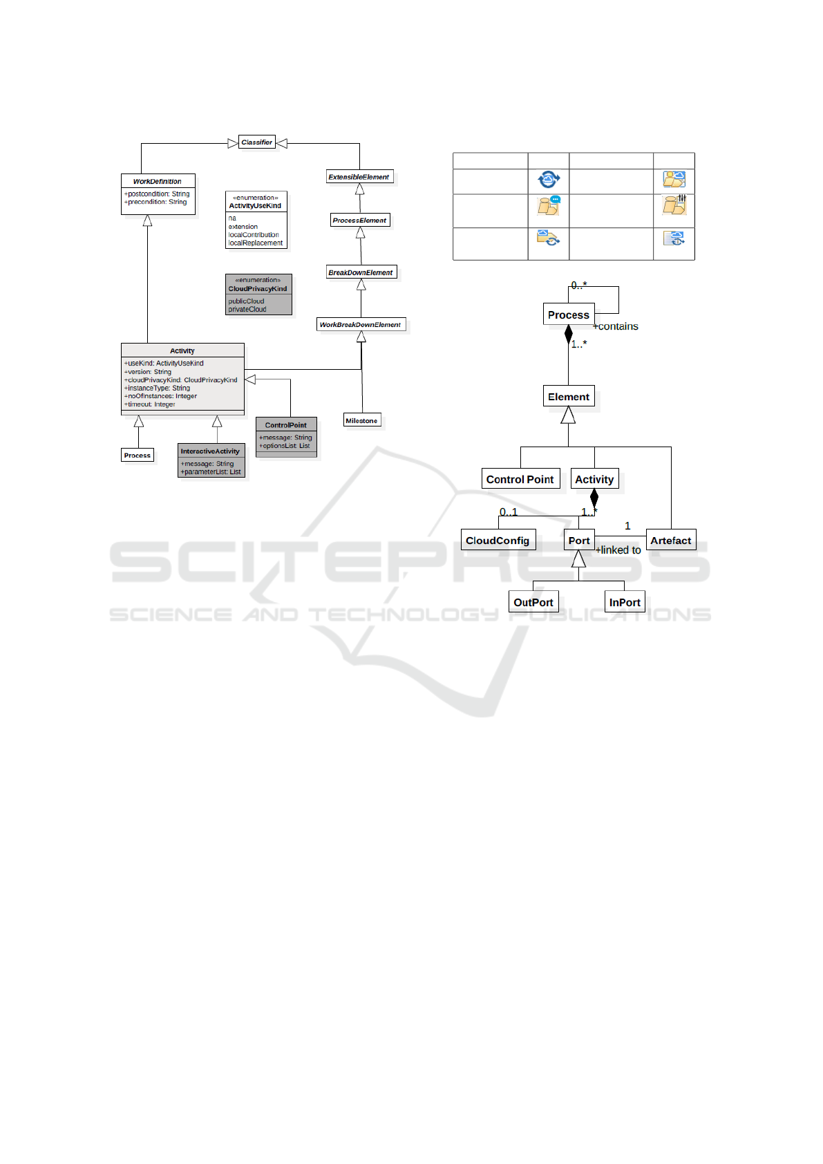
Figure 1: The meta-model of the extended SPEM 2.0 pro-
cess structure.
– The Control Point provides the semantics of
control flow in the process model. Control
points in the process model give the user ex-
ecuting the process control on deciding which
branch the execution should follow next. A
branch can be: a loop (referring to the same
activity), a fork or a join. The control point in-
teraction is simply done by providing options
(pre-defined in the model) and asking the user
to make a decision on which option to follow.
This meets requirement R4 and the decision
making interaction part of requirement R3.
– Interactive Activity which can be used to model
an activity that involves simple interactions
with stakeholders. This meets the parameter
passing type of interactions in requirement R3.
Icons for the EXE-SPEM elements are provided
in Table 1. It is worth noting that EXE-SPEM reuses
some of the SPEM2.0 elements (Role Use, Guidance,
Process Parameter and Work Sequence) with the same
icons. Furthermore, the difference between a Task and
Activity in EXE-SPEM is that the task is not supported
by a tool while the activity is.
Table 1: Graphical Icons of EXE-SPEM elements.
Element Icon Element Icon
Process Activity
Interactive
Activity
Control
Activity
Task Use
Work
Product Use
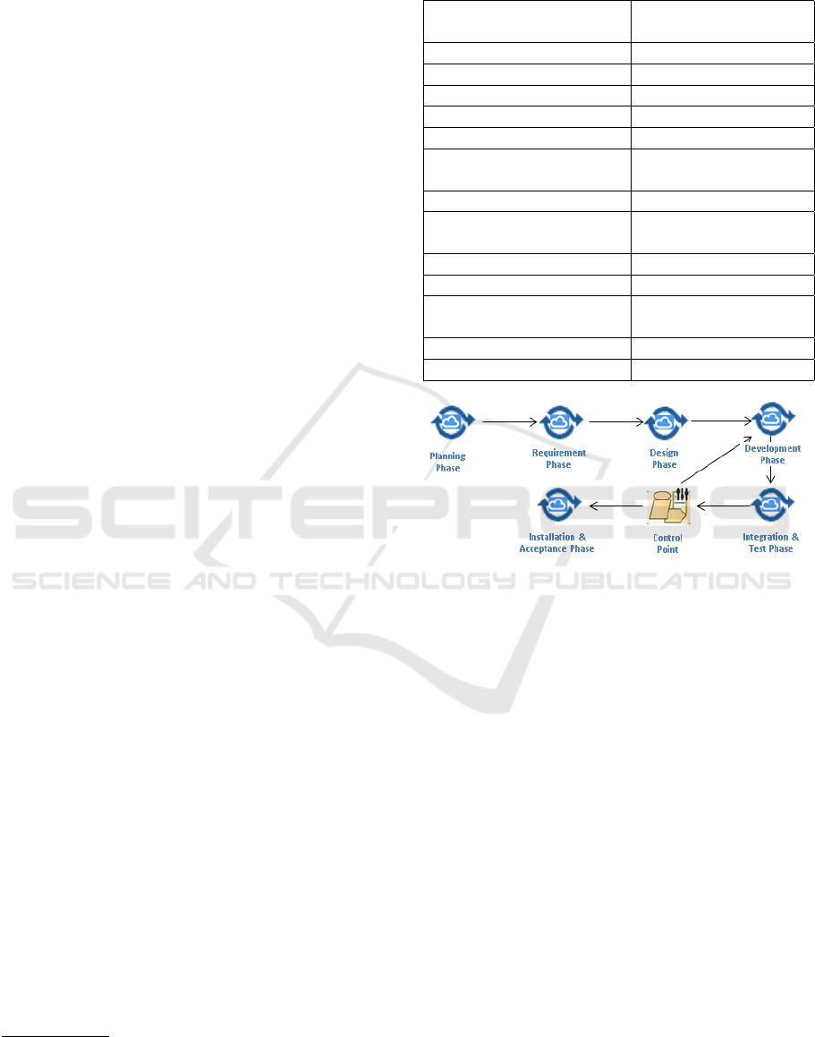
Figure 2: The meta-model of the XML schema.
6 XML NOTATION
In order to enact the EXE-SPEM model, we map it
to an executable XML format following the XML
schema in the Appendix. The meta-model of the
schema is described in Figure 2. The XML schema
captures a process consisting of the following ele-
ments:
• Process: this is the software development cycle.
A process is usually created by an actor but might
be performed by multiple actors.
• Actor: a person who is involved in the process
such as: process managers, software engineers,
testers, etc. A process will involve one or more
actors. Although a team of actors might collabo-
rate off-line on performing an activity, the activity
will be assigned to a single actor who takes the
responsibility for this activity.
• Artefacts: items produced or needed by the ac-
tivities of the software development process (e.g.
MODELSWARD 2016 - 4th International Conference on Model-Driven Engineering and Software Development
522
code, executables, models, documents, etc.).
• Activities: Activities represent the smallest unit
of execution. They represent the different steps
in a software production life cycle. Those steps
usually involve the use of tools and/or actor inter-
action to be completed. Activities can be:
– Concrete Activities: are executable blocks of
code. This type of activities is the tool sup-
port that is used for process execution. For in-
stance, a verification activity will be supported
by a verification tool (e.g. a model checker)
which will be executed.
– Control Points: a type of activities which al-
lows actors to guide the execution of the pro-
cess in one of multiple defined directions. This
allows for supporting loops, if conditions, and
forks.
• Cloud Configuration: represents cloud-related
configurations such as: cloud deployment type,
machine type, machine image, number of ma-
chines to be used, etc.
• Ports: Each activity can have zero or more input
ports and zero or more output ports. Ports pro-
vide the means to connect activities and direct the
process execution flow. They define both the con-
sumed and produced artefacts by an activity. In
addition, input ports act as preconditions that need
to be satisfied so that the activity can start execut-
ing.
Table 2 shows the rules to map an EXE-SPEM
model into the XML format described above. The
mapping include some SPEM2.0 elements which are
reused in EXE-SPEM. These elements are denoted
with *.
7 EXAMPLE PROCESS
In this section, we model parts of the software
process documentation example adopted from Shell
Method process repository
5
. Shell Method is an inte-
grated software development methodology designed
for business and operations-oriented database systems
that must pass audit. The example describes in detail
the life-cycle of an order entry and shipping opera-
tions database application project
6
.
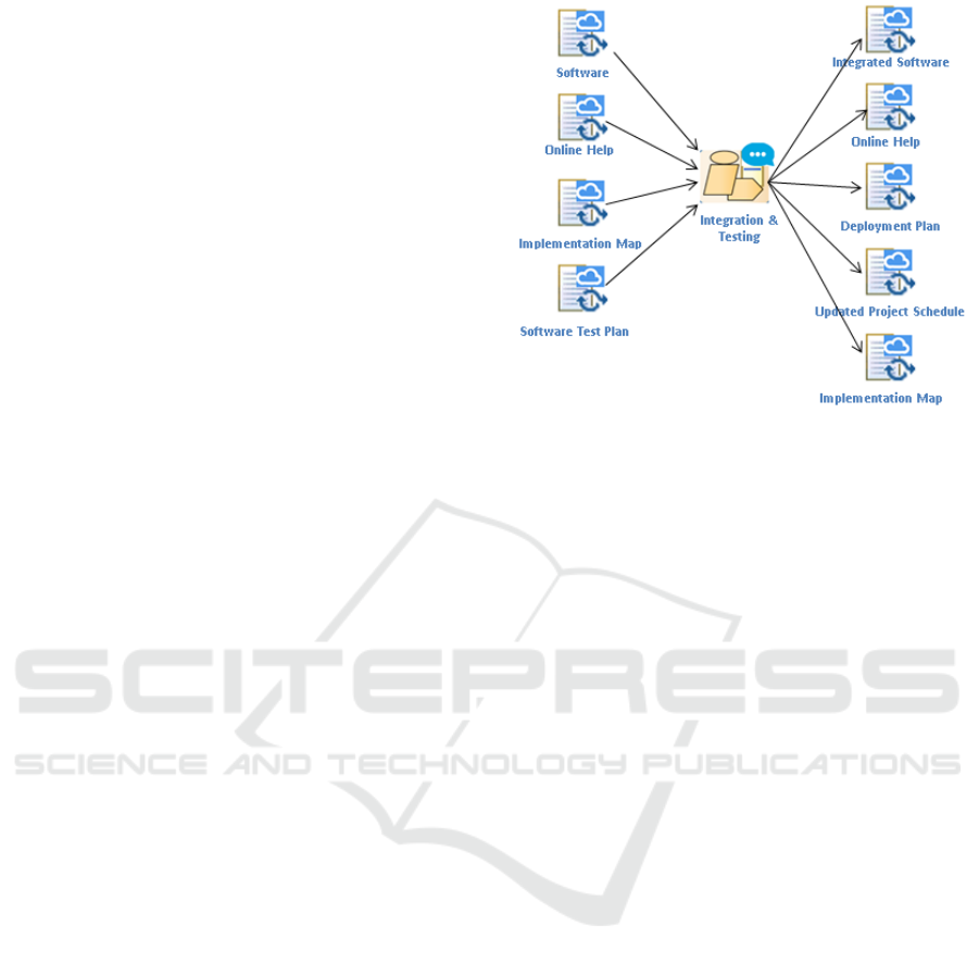
We modelled the high level stages of the project as
shown in Figure 3. In this model, a Control Point is
introduced after the Integration and Testing phase to
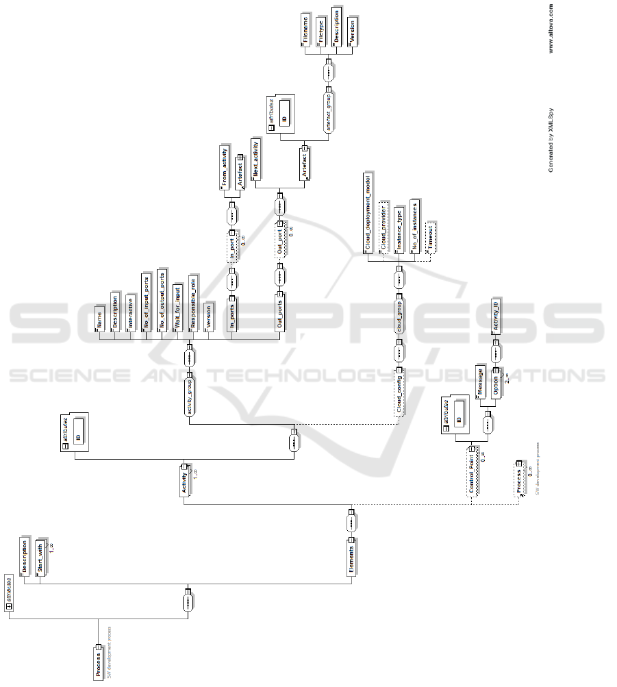
provide control flow in the process. Figure 4 shows
5
http://www.shellmethod.com/
6
http://shellmethod.com/refs/SDLC.pdf
Table 2: Mapping rules between EXE-SPEM and our XML
notation.
EXE-SPEM
cloud-specific process
XML Process
Process Process
Phase (Sub) Process
Activity Activity
Control Point
Control Point
Interactive Activity Interactive Activity
Activity (execution
-related) attributes
Cloud Configuration
(of an activity)
Task (supported by a tool) Activity
Task (Not supported
by a tool)
Activity description
attribute
Work Product Use Artefact
Role Use* Activity actor attribute
Guidance*
Activity description
attribute
Process Parameter* Port
Work Sequence* Port attributes
Figure 3: High level life-cycle process model in EXE-
SPEM.
the Integration and Testing stage of the life-cycle
modelled in EXE-SPEM. This process uses an Inter-
active Activity to allow the user to provide parameters
to run the integration tests. The Integration and Test-
ing activity takes four artefacts as an input (generated
from the Development stage) and produces six out-
come artefacts.
The life-cycle process model is mapped to an
XML model following the mapping rules in Table 2.
The following is a snippet of the XML model :
<Process>
<Elements>
......
<Process>
<Elements>
<Activity ID="560d33bce4v02180e944k92l">
<Name>Integration</Name>
<Description>
Integration and Testing stage
</Description>
<Interactive>true</Interactive>
<No_of_input_ports>4</No_of_input_ports>
<No_of_output_ports>6</No_of_output_ports>
<Wait_for_input>false</Wait_for_input>
EXE-SPEM: Towards Cloud-based Executable Software Process Models
523
<Responsible_role>
Integration Engineer
</Responsible_role>
<Version>1</Version>
<In_ports>
<In_port>
<From_activity>560d33bbe4b02110e7</From_activity>
<Artefact ID="560d33bbe4b02110e944c806">
......
</Artefact>
</In_port>
<In_port>
<From_activity>560d33bbe4b02110e8</From_activity>
<Artefact ID="560d33bbe4b02110e944c842">
......
</Artefact>
</In_port>
......
</In_ports>
<Out_ports>
<Out_port>
<Next_activity>560d33bbe4b02110e8</Next_activity>
<Artefact ID="560d33bbe4b02110e944b5j2">
......
</Artefact>
</Out_port>
......
</Out_ports>
<Cloud_config>
<Cloud_deployment_model>public
</Cloud_deployment_model>
<Cloud_provider>AWS</Cloud_provider>
<Instance_type>m3.xlarge</Instance_type>
<No_of_instances>2</No_of_instances>
<Timeout>2</Timeout>
</Cloud_config>
</Activity>
</Elements>
</Process>
<Control_Point ID="560d33bbe4b02110e8jm2n16">
<Message>Choose the next branch.</Message>
<Options>
<Option> <!-- Development-->
<ActivityID>560d33bbe4b02110e8</ActivityID>
</Option>
<Option> <!-- Installation & Acceptance-->
<ActivityID>560d33bbe4b02110e8</ActivityID>
</Option>
</Options>
</Control_Point>
</Elements>
</Process>
In contrast to SPEM2.0, using EXE-SPEM in the
above model has allowed to model interaction and
control flow semantics. In addition, the textual model
(XML) contains configurations that will used for en-
actment.
Figure 4: Integration and Testing process model in EXE-
SPEM.
8 CONCLUSIONS
Cloud computing is becoming the norm for comput-
ing resources delivery. However, its potential for soft-
ware processes has not been fully harnessed yet. In
this paper, we highlighted the potentials and concerns
of moving software processes to the cloud. We argued
that executable cloud-based software process models
can help with further adoption of the MDE approach
for software development. This will leverage the ben-
efits of both the cloud and MDE for software devel-
opment.
We introduced EXE-SPEM which is an extension
of the SPEM2.0 meta-model to capture cloud-based
execution information in software process models. To
demonstrate the use of EXE-SPEM, we used it to
model an example software process for database ap-
plication development. Currently, we are working on
developing a cloud-based enactment platform to ex-
ecute EXE-SPEM models. The new platform will
support integrating tools as services and execution of
software process models on a hybrid cloud. In addi-
tion, algorithms to automate the mapping between the
EXE-SPEM and the XML notation.
ACKNOWLEDGEMENTS
Alexander Romanovsky has been supported by the
EPSRC/UK TrAmS-2 platform grant on Trustwor-
thy Ambient Systems: Resource-constrained Ambi-
ence. Barbara Gallina has been supported by by
the Swedish Foundation for Strategic Research (SSF)
project SYNOPSIS.
MODELSWARD 2016 - 4th International Conference on Model-Driven Engineering and Software Development
524

REFERENCES
Alajrami, S., Romanovsky, A., Watson, P., and Roth, A.
(2014). Towards cloud-based software process mod-
elling and enactment. CloudMDE, page 6.
Azoff, M. (2008). White paper: The benefits of model
driven development. mdd in modern web based sys-
tems. Technical report, Butler Direct Limited, Hull,
East Yorkshire, UK.
Bendraou, R., Gervais, M.-P., and Blanc, X. (2006).
Uml4spm: An executable software process model-
ing language providing high-level abstractions. In
Enterprise Distributed Object Computing Conference,
2006. EDOC ’06. 10th IEEE International, pages
297–306.
Brooks, F. P. (1987). No silver bullet: Essence and accidents
of software engineering. IEEE Computer, 20:10–19.
Bruneli
`
ere, H., Cabot, J., and Jouault, F. (2010). Combining
Model-Driven Engineering and Cloud Computing. In
Modeling, Design, and Analysis for the Service Cloud
- MDA4ServiceCloud’10: Workshop’s 4th edition (co-
located with the 6th European Conference on Mod-
elling Foundations and Applications - ECMFA 2010).
Combemale, B., Cr
´
egut, X., Caplain, A., and Coulette, B.
(2006). Towards a rigorous process modeling with
SPEM. In ICEIS 2006 - Proceedings of the Eighth
International Conference on Enterprise Information
Systems: Databases and Information Systems Integra-
tion, Paphos, Cyprus, May 23-27, 2006, pages 530–
533.
Conradi, R., Jaccheri, M. L., Mazzi, C., Nguyen, M. N., and
Aarsten, A. (1992). Design, use and implementation
of spell, a language for software process modelling
and evolution. In Proceedings of the Second European
Workshop on Software Process Technology, EWSPT
’92, pages 167–177.
Ellner, R., Al-Hilank, S., Drexler, J., Jung, M., Kips, D., and
Philippsen, M. (2010). espem - a spem extension for
enactable behavior modeling. In Modelling Founda-
tions and Applications, volume 6138 of Lecture Notes
in Computer Science, pages 116–131.
Ellner, R., Al-Hilank, S., Drexler, J., Jung, M., Kips, D., and
Philippsen, M. (2011). A fuml-based distributed exe-
cution machine for enacting software process models.
In Modelling Foundations and Applications, volume
6698 of Lecture Notes in Computer Science, pages
19–34. Springer.
Emmerich, W. and Gruhn, V. (1996). Funsoft nets: A petri-
net based software process modeling language. In In
Proceedings of The Sixth International Workshop on
Software Specification and Design. 1991, IEEE Com-
puter Society, pages 175–184. IEEE Computer Soci-
ety Press.
Gallina, B., Pitchai, K., and Lundqvist, K. (2014). S-
tunexspem: Towards an extension of spem 2.0 to
model and exchange tunable safety-oriented pro-
cesses. In Lee, R., editor, Software Engineering Re-
search, Management and Applications, volume 496
of Studies in Computational Intelligence, pages 215–
230. Springer International Publishing.
Haan, J. D. (2008a). 8 reasons why model-
driven approaches (will) fail. Available at
www.infoq.com/articles/8-reasons-why-MDE-fails,
accessed on: 2015-10-16.
Haan, J. D. (2008b). Mda, model driven ar-
chitecture, basic concepts. Available at
www.theenterprisearchitect.eu/blog/2008/01/16/mda-
model-driven-architecture-basic-concepts/, accessed
on: 2015-10-16.
ISO (2014). ISO/IEC 24744:2014. ISO Standard, Interna-
tional Organization for Standardization (ISO).
Lawler, R. (2014). Microsoft ceo satya nadella says
we have entered the post-post-pc era. Available
at www.techcrunch.com/2014/05/27/microsoft-ceo-
satya-nadella-says-weve-entered-the-post-post-pc-
era/, accessed on: 2015-10-16.
Maximilien, E. M. and Campos, P. (2012). Facts, trends
and challenges in modern software development. Int.
J. Agil. Extrem. Softw. Dev., 1(1):1–5.
Mell, P. M. and Grance, T. (2011). Sp 800-145. the nist
definition of cloud computing. Technical report, Na-
tional Institute of Standards & Technology, Gaithers-
burg, MD, United States.
Mnch, J., Armbrust, O., Kowalczyk, M., and Soto, M.
(2012). Software Process Definition and Manage-
ment. Springer Publishing Company, Incorporated.
OASIS (2007). Web Service Business Process Execution
Langugae Version 2.0. OASIS Standard, OASIS.
OMG (2003). MDA Guide, version 1.0.1. OMG Standard,
Object Management Group (OMG).
OMG (2008). Software and Systems Process Engineering
Meta-Model Specification, V2.0. OMG Standard, Ob-
ject Management Group (OMG).
OMG (2014). Kernel And Language For Software Engi-
neering Methods (Essence), V1.0. OMG Standard,
Object Management Group (OMG).
Peuschel, B. and Sch
¨
afer, W. (1992). Concepts and imple-
mentation of a rule-based process engine. In Proceed-
ings of the 14th International Conference on Software
Engineering, ICSE ’92, pages 262–279. ACM.
Portela, C., Vasconcelos, A., Silva, A., Silva, E., Gomes,
M., Ronny, M., Lira, W., and Oliveira, S. (2012). xspi-
der
ml: Proposal of a software processes enactment
language compliant with spem 2.0. Journal of Soft-
ware Engineering and Applications, 5(6):375 – 384.
Schmidberger, M. and Schmidberger, M. (2012). Software
engineering as a service for hpc. In Parallel and Dis-
tributed Computing (ISPDC), 2012 11th International
Symposium on, pages 34–39.
Schmidt, D. C. (2006). Guest editor’s introduction: Model-
driven engineering. Computer, 39(2):25–31.
WFMC (2012). XML Process Definition Language 2.2.
WFMC Standard, Workflow Management Coaliation.
Yuan, F., Li, M., and Wan, Z. (2006). SEM2XPDL: to-
wards SPEM model enactment. In Proceedings of
the International Conference on Software Engineer-
ing Research and Practice & Conference on Program-
ming Languages and Compilers, SERP 2006, Las Ve-
gas, Nevada, USA, June 26-29, 2006, Volume 1, pages
240–245.
EXE-SPEM: Towards Cloud-based Executable Software Process Models
525
APPENDIX
XML Schema for Executable Software
Process Models
MODELSWARD 2016 - 4th International Conference on Model-Driven Engineering and Software Development
526
