
Abstracting Data and Image Processing Systems using a
Component-based Domain Specific Language
Thomas Hoegg, Christian Koehler and Andreas Kolb
Computer Graphics and Multimedia Systems Group, University of Siegen, Hoelderlinstr. 3, 57076 Siegen, Germany
Keywords:
Modeling, Components, Domain-specific Languages, Image Processing.
Abstract:
This work proposes a textual and graphical domain-specific language (DSL) designed especially for modeling
and writing data and image processing algorithms. Since reusing algorithms and other functionality leads to
higher program quality and mostly shorter development time, this approach introduces a novel component-
based language design. Special diagrams and structures, such as components, component-diagrams and
component-instance-diagrams are introduced. The new language constructs allow an abstract and object-
oriented description of data and image processing tasks. Additionally, a compatible graphical design interface
is proposed, giving modelers and architects the opportunity to decide which kind of modeling they prefer
(graphical or textual, including round-trip engineering).
1 INTRODUCTION
The requirements on software systems were rising
dramatically during the last years. Especially the
usage of complex software architectures for techni-
cal applications, such as image processing or sim-
ilar (sensor-) data processing tasks, has heavily in-
creased due to cheaper and more powerful hardware.
While system requirements become more and more
complex, the time to market should be shortened and
the software quality should be improved at the same
time. Setting up new data and image processing sys-
tems is an always recurring task. Having predefined
domain-specific languages (DSLs) and tested generic
default runtime architectures, supporting functional-
ity as Graphical-User-Interface (GUI) and algorithm
interaction can catalyze development. As an add-
on on top of a data processing runtime, component-
based software engineering (CBSE) can help sepa-
rating data processing problems and algorithms into
packed, reusable software components. After design-
ing such a component, engineers and developers are
able to instantiate it and connect it to other compo-
nents using predefined interfaces. However, one of
the biggest drawbacks in the domain of data and im-
age processing is that no real standard architecture has
been established yet.
During the past years, several techniques have
been established in software engineering but are
rarely used for image processing. The two most im-
portant approaches are graphical modeling and DSLs.
Graphical modeling gives modelers the possibility to
create a relatively simple, high-level, iterative graph-
ical architecture design, where all relevant parties
(programmers and non-programmers as e.g. project
leaders) can have an abstract but graphical view on
the system in development. This can help with iden-
tifying and solving problems at an early stage. DSLs
are the second important approach. While the con-
cept of DSLs has been known for a long time, they
have gained much importance in the last years due
to tools simplifying the language development, e.g.
Xtext (Efftinge et al., 2015). DSLs are divided into
two types: internal and external DSLs (Fowler, 2010).
Internal DSLs use the existing infrastructure of host
programming languages. Examples for such DSLs
are OpenCL or OpenGL. Both languages are a C di-
alect, extending C to their requirements. External
DSLs however are designed from scratch after a full
analysis of the problem description. Using special
keywords, abstractions and control structures, they
are able to illustrate complex problems mostly in sim-
pler and more compressed forms. A big drawback is
that the whole infrastructure such as parsers, lexers
and compilers has to be built. Well-known examples
are the Unix shell scripts or SQL.
Both kinds of approaches, graphical modeling and
also external DSLs, are unfortunately hardly used in
the domain of image processing and computer vision.
Developers mainly want to concentrate on algorithm
292
Hoegg, T., Koehler, C. and Kolb, A.
Abstracting Data and Image Processing Systems using a Component-based Domain Specific Language.
DOI: 10.5220/0005743502920300
In Proceedings of the 4th International Conference on Model-Driven Engineering and Software Development (MODELSWARD 2016), pages 292-300
ISBN: 978-989-758-168-7
Copyright
c
2016 by SCITEPRESS – Science and Technology Publications, Lda. All rights reserved
development and not on software design issues. This
is why we propose GU-DSL, an external data and im-
age processing related language, combining graphical
and textual modeling to reduce architecture and sys-
tem design times. For this purpose we contribute the
following novel main features:
• A language concept and implementation of com-
ponents using ports and interfaces based on Xtext
• Class-, component- and novel component-
instance-diagrams for component and system
design
• A textual and graphical tool infrastructure using
Eclipse Xtext and GMF
The remainder of this paper is organized as fol-
lows: Sec. 2 explains the newly proposed language
and software architecture concept. In Sec. 3, we show
our novel DSL features. Sec. 4 exhibits an image pro-
cessing modeling example. In Sec. 5, the related work
to this paper is discussed. Sec. 6 concludes this paper.
2 SYSTEM CONCEPT AND
OVERVIEW
GU-DSL is a diagram based, object oriented mod-
eling language supporting structural- and behavior-
modeling in a textual and graphical, model driven
way. Using a Java and C# like syntax, it is easy to
learn and offers an abstract way for textual modeling
of especially data and image processing tasks. Apart
from using class- and activity-diagrams to model ob-
jects and system behaviors, it gives architects the pos-
sibility for sequential behavior coding using an em-
bedded expression language. The DSL’s activity-
diagrams and the expression language are just men-
tioned for completeness and are not part of this paper.
The paper proposes a novel component-based
language in a textual and graphical form. For
component-oriented modeling, we pick up the basic
concepts specified in literature as interfaces, classes,
components, ports and interface connections and in-
tegrate them in a novel way into our DSL. Hence,
we add special novel keywords, structures, compo-
nent implementations and communication concepts
that we will show in the following sections.
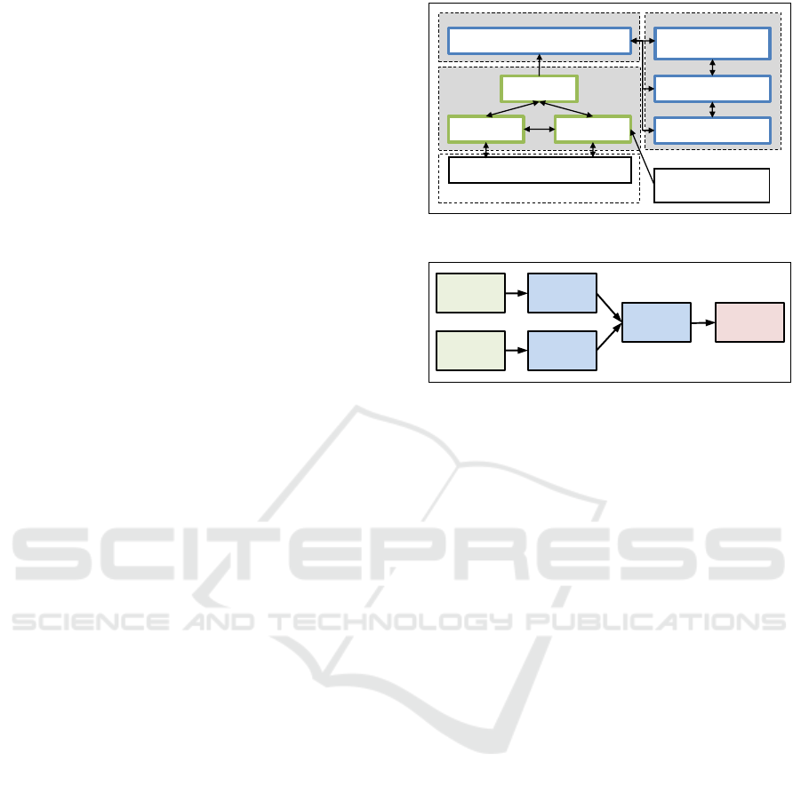
Fig. 1 shows the principle setup of the frame-
work. The contributed parts with this paper are high-
lighted in green. Three collaborating system parts
are comprised: modeling, code-generation and the
framework runtime. The basis of our system is built
in Eclipse in combination with some modeling plug-
ins such as Xtext (a DSL generation language) and
Eclipse Xtext/GMF/Java
Basic-GU-DSL
(Xtext-DSL)
C/C++/OpenCL-Code Generator
GMF-Editors
OpenGL-GUI-Framework
Heteregenous Computing
Framework
Real-World-Problem
Description/Algorithm
Modeling
Optional: Generation
Runtime
Optional: Framework Runtime
Component-
based GU-DSL
C++ CBSE Framwork
Figure 1: The principle schema of the modeling framework.
Camera
(Source)
Camera
(Source)
Mean
(Filter)
Viewer
(Sink)
Mean
(Filter)
Merge
(Filter)
Figure 2: An image processing example using several com-
ponents.
GMF (Graphical Modeling Framework). On top
of Eclipse, there is our DSL-modeling environment.
It contains three interacting parts: the basic DSL
(class- and activity-diagrams, expression language),
the component-based language parts and the GMF ed-
itors allowing for graphical modeling. By using the
modeling part, the system architect can easily abstract
real-world problems and algorithm descriptions and
use the model as input for the future code generator.
Data and image processing tasks can rapidly grow
in complexity. The abstraction towards reusable com-
ponents helps handling this. Having a look on such a
processing system (see our example in Fig. 2) shows,
that we generally have a pipeline system starting with
a source (often a camera, sensor or a database), con-
tinuing with filters (e.g. noise reduction or data eval-
uation) and finishing with sinks (e.g. showing or stor-
ing data). In software-engineering, this problem de-
scription can be mapped by the pipe and filter ar-
chitectural pattern, allowing pipeline based data pro-
cessing. It serves as a basis for our novel language
concept as we will show in the next sections. A de-
tailed description of the particular DSL parts can be
found in Sec. 3.
Components form the basis of our system. In-
terfaces, known e.g. from UML and SysML, allow
communication between components. The direction
depends on the interface definition and can be either
uni- or bi-directional. The DSL is defined with the
following restrictions:
• Sources: Outgoing communications (uni-
directional)
Abstracting Data and Image Processing Systems using a Component-based Domain Specific Language
293

• Filters: Incoming and outgoing communications
(bi-directional)
• Sinks: Incoming communications (uni-
directional)
Ports are used as flexible input and output points
of components by providing required interfaces. Ev-
ery port is uniquely assigned to a component and can
be connected to other valid ports, allowing a prede-
fined, direct communication as we will see in the later
sections.
3 THE COMPONENT BASED
ENGINEERING LANGUAGE
GU-DSL is a language especially designed for object-
oriented modeling of data and image processing prob-
lems. Different to other languages in this domain, it
is designed in a way that model driven problem so-
lutions, both textual and graphical, are the main fo-
cus. Other languages often concentrate on the com-
pression and simplification of code only.
This section shows all the features required for
understanding our concept and novel ideas. Com-
ponents are a well established concept in software
engineering, however, the novel contribution of this
approach is the way how all the different diagrams
(class-, activity- and component-diagrams) and lan-
guage features interact to reduce future errors and
to speed up development. Especially the way how
components interact with classes, types and meth-
ods using behavior-diagrams or sequential coding are
unique in this domain and will be shown in the fol-
lowing section. Additionally, the proposed compo-
nent approach can be used standalone for architectural
design and modeling in the sense of Architecture De-
scription Languages (ADL).
To better support reusable components, we split
our system into two main parts:
1. Component-diagrams
2. Component-instance-diagrams
As typical for ADLs, this gives architects the op-
portunity of splitting a system into an architectural
modeling layer (component-diagrams, where the ba-
sic system setup can be defined) and an instantiation
layer (component-instance-diagrams, where compo-
nents can be instantiated). This can be partly com-
pared to the OMG Meta-Object-Facility (MOF, a four
layer modeling architecture (OMG, 2015c)).
The following sections will introduce all neces-
sary new language features.
3.1 Interface Definitions
A central role in our language is played by inter-
faces. GU-DSL supports standard interfaces (known
e.g. from UML), but for our novel component ex-
tension, they are not sufficient. To make the system
type- and communication-safe, we introduce two spe-
cial keywords: processor and provider. As shown
in Listing 1, the new keywords can directly be ap-
plied to either defining an output-interface (provider)
or an input-interface (processor). The keywords clas-
sify the new interface types to be usable with compo-
nent ports, as will be shown in Sec. 3.3.
1 I n t e r f a c e :
2 v i s i b i l i t y = ( ’ p u b l i c ’ | ’ p r o t e c t e d ’ | ’
p r i v a t e ’ ) ? ’ i n t e r f a c e ’
3 ( ’ p r o v i d e r ’ | ’ p r o c e s s o r ’ ) ? name=ID
4 ’{ ’ ( method s +=Method ) ∗ ’ } ’
Listing 1: Component interface definitions.
An automatic communication specialization has
been added in a way, that a provider-interface can talk
to a corresponding processor-interface only. For this
purpose, there is a restriction that a provide-method-
signature needs a corresponding process-method-
signature as can be seen in our example in Listing 8.
It simplifies the usage, makes automatic code genera-
tion easier and allows for complete model validation.
Which processor and which provider interface corre-
sponds to each other can be defined in the component-
diagram by connecting ports (see Sec. 3.3).
3.2 Component Definitions
Components and their simple (re-)usage are the cen-
tral new contribution of our paper. In our approach,
they are directly interconnected with the class-system
known from UML class diagrams and are the base of
our system architecture definition.
Therefore, an important novel idea is introduced
with our class diagrams. The keywords source, filter
and sink can be used in a similar way as the standard
class-keyword (see Listing 2). Stemming from the
domain of data and image processing, these special
keywords characterize the components as specified in
Sec. 2.
Once having a component-class defined, it is
used as basis for the final component. Designing
components this way gives architects the possibil-
ity to split the definition (component-diagram) from
the concrete implementation (class-diagram, activity-
diagram). Components are designed in the newly
introduced component-diagrams (Listing 3). As for
class-diagrams, there are also the three main types
MODELSWARD 2016 - 4th International Conference on Model-Driven Engineering and Software Development
294

(source, filter, sink) available. To support generic
components that cannot be mapped to these three
types, the class-keyword is usable. The component
definition syntax (see Listing 3) itself is quite simple:
it is the previously defined fully qualified name (Fqn)
used in the class-diagram (see Listing 2). As class-
and activity-diagrams, component-diagrams support
nesting of additional components in arbitrary depth
as can be seen in Listing 3.
1
2 C l a s s D i a g r a m :
3 ’ Clas s D ia g r a m ’ name=ID
4 ’{ ’
5 c l a s s e s += B a s e C l a s s ∗
6 ’ } ’ ;
7
8 B a s e C l a s s :
9 v i s i b i l i t y =( ’ p u b l i c ’ | ’ p r o t e c t e d ’ | ’ p r i v a t e ’ ) ?
10 ( ’ c l a s s ’ | ’ so u r c e ’ | ’ f i l t e r ’ | ’ s i n k ’ ) name=ID
11 ’{ ’
12 ( f i e l d s += F i e l d ) ∗
13 ( methods +=Method ) ∗
14 ’} ’
Listing 2 : Class-diagram and class definitions.
For embedded components, the same design prin-
ciples are applicable as for all other components.
That means the underlying classes have to be defined
first and ports have to be used in the same way (see
Sec. 3.3).
1 Comp o n e ntDiagr a m :
2 ’ C omp one ntD iag ram ’ name=ID
3 ’{ ’
4 ( comp o n e nts += Component ) ∗
5 ’ } ’ ;
6
7 Component :
8 ( ’ c l a s s ’ | ’ so u r c e ’ | ’ f i l t e r ’ | ’ s i n k ’ | name = [ B a s e C l a s s |
Fqn ]
9 ’{ ’
10 ( comp o n e nts += Component ) ∗
11 ( p o r t s += P o r t ) ∗
12 ( c o n n e c t i o n s += C o n n e c t i o n ) ∗
13 ’ } ’ ;
Listing 3: Component-diagram and component defini-
tions.
3.2.1 Component Interfaces
Components require interfaces to be able to commu-
nicate. Hence, two types of component interface im-
plementations are provided:
1. Interfaces by inheritance
2. Anonymous interfaces
Interfaces by Inheritance. are the default inter-
faces that should be used during the component def-
inition. In this case, the component classes inherit
from the necessary interfaces and provide all the
methods that can later be used by ports and during the
component functionality implementation. An impor-
tant feature is that in this case, the interfaces meth-
ods have to be implemented only, if they require a
special implementation. Otherwise, they are automat-
ically available assuming a default implementation.
This has the advantage of interface methods being di-
rectly accessible and usable without any additional
code. However, if a special kind of implementation
is required, the interface methods can also be imple-
mented using our DSL.
Anonymous Interfaces. are a special version of in-
terface implementations. In this case, the component
class does not have to implement the interface, but the
interface method can still be called directly, e.g. in the
DSL’s sequential expression language. Therefore we
have added a new kind of interface call (Listing 4).
1 I n t e r f a c e C a l l :
2 ( ’ c a l l ’ ( ’ i n t e r f a c e ’ ) ? ) ? i n t e r f a c e N a m e =Fqn ’ . ’
methodName=ID
3 ’ ( ’ p a r a m e t e r V a l u e s += P a r a m e t e r V a l u e
4 ( ’ , ’ p a r a m e t e r V a l u e s += P a r a m e t e r V a l u e ) ∗ ’ ) ’
Listing 4: Anonymous interface calls.
Anonymous interfaces are completely loose and
the full interface definitions do not have to be avail-
able during design time. This gives designers the pos-
sibility to model components without having the full
interface code. It can also be used to call interface
methods from arbitrary places during component ex-
ecution.
3.3 Port Definitions and Connections
Ports are the door to the outer and inner world of com-
ponents. Allowing data exchange between compo-
nents and nested components, ports provide the abil-
ity to define interfaces that handle how data can be
transferred to and from a component. Therefore the
previously defined interfaces (see Listing 1) can be
chosen. The port definition within a component has a
simple syntax (see Listing 5).
1 P o r t :
2 ( ’ asy n c ’ ( ’ b u f f e r e d ’ ) ? ) ? ’ p o r t ’ name=Fqn
3 ’ ( ’ c o n n e c t o r s += C o n n e c t o r
4 ( ’ , ’ c o n n e c t o r s += C o n n e c t o r ) ∗ ’ ) ’
5
6 C o n n e c t o r :
7 ’ p r o c e s s o r | ’ p r o v i d e r ’ name=Fqn ’ : ’ i n t e r f a c e r e f =[
I n t e r f a c e | Fqn ] ;
8
9 C o n n e c t i o n :
10 ’ [ ’ name=ID ’ s o u r c e ’ s o u r c e p o r t =[ C o n n e c t o r | Fqn ] ’==>’
’ t a r g e t ’ t a r g e t p o r t =[ C o n n e c t o r | Fqn ] ’ ] ’ ;
Listing 5: Port and Connection definitions.
The special preceded keyword async characterizes
the port to be asynchronous, which means commu-
nication is forced to be non-blocking. Compared to
standard blocking ports, a called interface method di-
rectly returns to the component and its sequential ex-
ecution. A special variant of asynchronous ports are
Abstracting Data and Image Processing Systems using a Component-based Domain Specific Language
295

buffered ports. Incoming data can be buffered and is
forwarded to the component if needed.
The detailed usage of components in combination
with interfaces and ports can be found in our example
in Sec. 4.
Ports play an important role when designing the
system. By connecting two ports (source ==¿ tar-
get), we define which interfaces and which interface
methods can be connected in the component-instance-
diagram (see Sec. 3.4).
Once all components, interfaces, ports and con-
nections are defined, the architecture definition is
completed and the instantiation phase can begin as we
will show in the next sections.
3.4 Component Instance Definitions
Once components have been designed and interface/-
port wiring is completed, the architectural definition
can be used in the component-instance-diagram. The
component-instance-diagram is an important new fea-
ture we have added to be able to reuse components
and to guarantee a type- and interface-safe compo-
nent wiring. The diagram can be compared to the
object-diagram known from UML, but it is specially
designed for component based engineering. Splitting
the instantiation from the definition of types and ob-
jects is a well-known practice in software engineer-
ing, but is not fully established for component based
ADL approaches (or also UML) in this form.
The separation of definition and instantiation en-
sures two things:
1. Defined components can simply be reused and
parametrized
2. Interface connections can be checked for validity
during design
Using the component and port definitions of the
component-diagram, the component instantiation can
be realized as shown in Listing 6.
While the component definition just defines fields
and methods in the class declaration, the instantiation
step assigns a unique instance name and initialization
values to a component and its fields. Three points are
necessary to completely instantiate a component. The
first one is a unique name. As second point, the com-
ponent type has to be assigned using the fully quali-
fied name of a component defined in the component-
diagram. The third important point is the assignment
of new initialization values. They can directly be as-
signed within two parentheses after the type specifi-
cation by a name-value combination.
1 C o m p o n e n t I n s t a n c e D i a g r a m :
2 ’ C o mp o n e n t In s t an c e D i a gr a m ’ name=ID
3 ’{ ’
4 c o m p i n s t a n c e s += C o m p o n e n t I n s t a n c e ∗
5 ’ } ’ ;
6
7 C o m p o n e n t I n s t a n c e :
8 name=ID ’ i n s t a n t i a t e s ’ co mponentT y p e =[ B a s e C l a s s | Fqn ]
9 ’ ( ’ ( fi e l d N a m e +=ID ’= ’ f i e l d V a l u e = F i e l d V a l u e
10 ( ’ , ’ f i e l d N a m e +=ID ’= ’ f i e l d V a l u e = F i e l d V a l u e )
∗) ? ’) ’
11 ’{ ’
12 ( p o r t s += C ID P or t ) ∗
13 ( ( b i n d i n g s += B i n d i n g ) ∗)
14 ( c o m p i n s t += C o m p o n e n t I n s t a n c e ∗ ) ?
15 ’ } ’ ;
Listing 6: Component instance definitions.
Besides the component instantiation, the other im-
portant step is having connections allowing the com-
munication and data-exchange between components.
For this purpose, instances of ports are created first.
Newly instantiated ports can then be wired. This syn-
tax can be seen in Listing 7.
1 C I D P o r t :
2 name=ID ’ : ’ ty p e =ID
3 ’ ( ’ c o n n e c t o r s += CI D C o n n e c to r ( ’ , ’ c o n n e c t o r s +=
CI D C o nn e c to r ) ∗ ’ ) ’ ’ ; ’ ;
4
5 C I D C on n e c t o r :
6 ’ p r o c e s s o r ’ | ’ p r o v i d e r ’ name=ID ’= ’
p r o c e s s o r I n t e r f a c e T y p e =Fqn
7 ’ ( ’ ( fi e l d N a m e +=ID ’= ’ f i e l d V a l u e = F i e l d V a l u e ( ’ , ’
f i e l d N a m e +=ID ’= ’ f i e l d V a l u e = F i e l d V a l u e ) ∗) ? ’ ) ’ ;
8
9 B i n d i n g :
10 ( ’ [ ’ ’ s o u r c e ’ s o u r c e p o r t = [ CI D C o n n e c to r | Fqn ] ’==>’
’ t a r g e t ’ t a r g e t p o r t =[ CI D C o nn e c to r | Fqn ] ’ ] ’ ) ;
Listing 7: Component connection definitions.
Connections are possible between processor and
provider ports only. This is guaranteed by the
architecture definition specified in the component-
diagram. Validity checks can be applied by an OCL
(Object Constraint Language, see (OMG, 2015d))
model validator (used in our approach) or any other
kind of validator. Depending on the final kind of code
generation and how ports are implemented on the tar-
get platform, it is also possible to initialize and assign
values to port instances. This can e.g. be necessary
for buffered ports shown in Listing 5, giving the op-
portunity to define the buffer size and so forth.
The connections are created between instantiated
ports. Only port instances are used as source or target.
The direction is unidirectional and it does not matter
if the source is a provider and the target a processor
or vice versa.
3.5 Component Initialization and
Execution
While the previous sections have shown how compo-
nents can be defined in general, this section shows
how they can be implemented. Hence, three meth-
MODELSWARD 2016 - 4th International Conference on Model-Driven Engineering and Software Development
296

ods are automatically available. The first one is re-
sponsible for initialization (init()) and it is assumed to
be called during the instance initialization, while the
second method is called during the component exe-
cution process(). The third important method is the
cleanup() and is responsible to release e.g. memory
or other resources. It is important to know that we
assume, that the process()-method is executed in a
thread. But this depends on the code-generator and
the underlying CBSE framework. The implementa-
tion of all three methods is performed in the corre-
sponding component class, either by using activity-
diagrams or sequential code as we show in our exam-
ple in Sec. 4.
3.6 Graphical Design Assistance
Besides the textual new features, we have also added
special graphical editors allowing full graphical mod-
eling in the sense of model driven development. Us-
ing graphical editors, system architects profit from the
higher level of abstraction. Multiple lines of code can
be added by drag and drop operations from a toolbox,
placing e.g. complete components on a component-
diagram. Also, connections can intuitively and in-
teractively be added by simply selecting source and
target ports. Sequential coding of method implemen-
tations is added using in-place editors supporting the
full language specification, especially the expressions
language. This gives architects the possibility to de-
cide on their own, if they prefer either textual, graph-
ical or mixed design. Since textual and graphical
representations are fully compatible (round-trip engi-
neering), the designer starts e.g. with textual model-
ing and can go over to graphical modeling and vice
versa. This can facilitate the entry to this new kind of
programming language and the component based en-
gineering. An example of the graphical design system
can be seen in Sec. 4.
3.7 Summary
The previous sections have introduced our novel
textual and graphical language contributions as
provider and processor interfaces, components,
ports, component-instances and also component- and
component-instance-diagrams. We have shown how
components can be designed and how they can be
connected using ports and interfaces.
Once the system architecture is specified in the
class- and component-diagrams, component, port and
connection instances have to be created in the novel
component-instance-diagram. The separation of defi-
nition and instantiation in this case has the big advan-
tage of giving two clear points of view onto the system
implementation. Furthermore, the new component-
instance-diagrams give the opportunity to uniquely
name and initialize the component and port instances.
By the usage of e.g. OCL validators, it is guaranteed
that names and field-value assignments are unique
and that instantiated component connections are ap-
plicable (provider to processor only).
All the previously introduced novel language fea-
tures allow for a complete architectural system speci-
fication and instantiation. An example system can be
found in Sec. 4.
4 A COMPONENT BASED
MODELING EXAMPLE
In the next sections, we will show a small image pro-
cessing example scenario to evaluate and demonstrate
the simplicity and flexibility of our new modeling lan-
guage (see also Fig. 2). A Camera-component (e.g. a
color camera) acquires an image, which is mean-value
filtered in the MeanFilter-component. At the end, the
image is shown in the Viewer-component. We start
with the definition of the necessary classes and inter-
faces in Listing 8.
Until now, we have defined the three main com-
ponent classes and the corresponding image proces-
sor and image provider interfaces. The classes imple-
ment their required interfaces as shown in Sec. 3.2.
Furthermore, they implement the required compo-
nent process-method by calling the responsible ac-
tivity diagrams (not part of this example). List-
ing 9 shows the usage of the classes as basis for
components. The components themselves define all
valid ports (CameraImageProviderPort, MeanImage-
ProcessorPort, MeanImageProviderPort, ViewerIm-
ageProcessorPort) and connections (CameraToFilter,
FilterToViewer) describing the final software archi-
tecture. As stated in Sec. 3, this means that we define
which components are connectable. In this example,
we allow the connection between a Camera and a pro-
cessing MeanFilter and also the connection between
a MeanFilter and a Viewer.
As can be seen, the basic architecture definition
is quite simple. While Listing 9 shows the required
component definitions and thus the developed archi-
tectural definition, Listing 10 instantiates the final
system using a component-instance-diagram (Com-
ponentInstanceExampleDiagram). It creates two
Camera instances (Camera1, Camera2), a MeanFilter
(MeanFilter1) and also a Viewer (Viewer1). Property
values are also assigned during creation.
Abstracting Data and Image Processing Systems using a Component-based Domain Specific Language
297

1 C la s s D i a g r a m C o m p o n e n t C l a s s D e f i n i t i o n s
2 {
3 p u b l i c i n t e r f a c e p r o v i d e r II m a g e P r o v i d e r
4 { / / se e a l s o t h e c o r r e s p o n d i n g p r o c e s s I m a g e
s i g n a t u r e
5 p u b l i c vo i d pr o v i d e I m a g e ( r e f Im age i m a g e ) ;
6 }
7
8 p u b l i c i n t e r f a c e p r o c e s s o r I I m a g e P r o c e s s o r
9 { / / se e a l s o t h e c o r r e s p o n d i n g p r o v i d e I m a g e
s i g n a t u r e
10 p u b l i c vo i d p r o c e s s I m a g e ( r e f Image im a ge ) ;
11 }
12
13 p u b l i c s o u r c e Camera im p l e m e n t s I I m a g e P r o v i d e r
14 {
15 p u b l i c i n t wi d t h ;
16 p u b l i c i n t h e i g h t ;
17
18 p u b l i c bo o l p r o c e s s ( C o n s t I O b j e c t P a r a m e t e r s P t r
p a r a m e t e r s )
19 { / / C a l l t h e a c t i v i t y −d i a g r a m r e s p o n s i b l e f o r
20 / / image a c q u i s i t i o n
21 c a l l b e h a v i o r Ad A c q u i r e I m a g e ;
22 r e t u r n t r u e ;
23 }
24 }
25
26 p u b l i c f i l t e r M e a n F i l t e r im p l e m e n t s I I m a g e P r o v i d e r ,
I I m a g e P r o c e s s o r
27 {
28 p u b l i c bo o l p r o c e s s ( C o n s t I O b j e c t P a r a m e t e r s P t r
p a r a m e t e r s )
29 { / / C a l l t h e mean f i l t e r a c t i v i t y −d i a g r a m
30 c a l l b e h a v i o r A d F i l t e r M e a n ;
31 r e t u r n t r u e ;
32 }
33 }
34
35 p u b l i c f i l t e r Viewe r im p l e m e n t s I I m a g e P r o c e s s o r
36 {
37 p u b l i c bo o l p r o c e s s ( C o n s t I O b j e c t P a r a m e t e r s P t r
p a r a m e t e r s )
38 { / / C a l l t h e a c t i v i t y −d i a g r a m t o show a new imag e
39 c a l l b e h a v i o r AdShowImage ;
40 r e t u r n t r u e ;
41 }
42 }
43 }
Listing 8: Component class example diagram.
Furthermore, all required port instances (Cam-
era1ProviderPort, Camera2ProviderPort, MeanPro-
cessorPort, MeanProviderPort, ViewerProcessor-
Port) are created. Finally, the ports are connected. As
already mentioned, the instantiation of ports and also
the connections are restricted to the fixed definitions
in Listing 9.
As stated in Sec. 3.6, besides the textual DSL, we
also propose graphical editors with this approach. It
rounds off the new component system approach as
can be seen in Fig. 3. The textual class-, component-
and component-instance-diagrams are shown in their
graphical version. While the textual form grows up
relatively fast, the graphical representations are more
compressed and much simpler to understand, which
can simplify design.
The listings and figures in this section show a
representative small example of the newly proposed
DSL component features. Starting with the class-
and interface-definitions (Listing 8), continuing with
the component design (Listing 9) and finishing with
the component instance definitions (Listing 10), the
example creates a small image processing pipeline
(Two cameras -¿ mean-filter -¿ viewer) in a textual
and graphical form.
By using e.g. a code generator, the example can be
transformed into compilable code. A reference imple-
mentation of a corresponding C++ CBSE system can
be found in (Hoegg et al., 2015).
1
5 RELATED WORK
This paper presents a novel DSL designed for textual
and graphical, component based modeling. The next
sections will have a look at some related work.
Several related languages and software engineer-
ing frameworks have been developed during the last
years. Architecture Description Languages (ADLs)
play an important role for this development, allowing
description of hardware as well as software architec-
tures. We exemplary compare our DSL and its infras-
tructure with the most important of them.
A very early approach of formal architecture def-
initions is Wright (Allen and Garlan, 1997). It was
introduced by R. Allen et. al in 1997, proposing ways
how components can be interconnected.
In (Magee et al., 1993), Magee et al. have intro-
duced Darwin, a configuration language that allows
for grouping process instances (an early kind of mod-
ern components) communicating by message passing.
Another standardized example of an ADL is
AADL (Feiler et al., 2005). It was developed es-
pecially for automotive embedded hard- and soft-
ware real-time systems, supporting several different
types as devices, buses, processors (hardware-side)
and threading or data processing (software-side). Fur-
thermore, it can encapsulate visible functionality into
connectable components.
UML (OMG, 2015e) and SysML (OMG, 2015f)
are standardized, ADL like languages supporting
structural, sequential and behavioral graphical mod-
eling of real world problems. They are proposed to be
generic applicable system and architecture languages,
giving architects the possibility of graphically design-
ing and solving problem descriptions.
Besides ADLs, also other related component
based approaches and frameworks have been installed
in several domains of software engineering in the past
two decades.
An early example of a component based robotic
controlling framework is SmartSoft (Schlegel and
Wrz, 1999) on basis of CORBA (Common Object Re-
quest Broker Architecture (OMG, 2015a)).
1
Examples and additional material: http://www.gu-
dsl.org
MODELSWARD 2016 - 4th International Conference on Model-Driven Engineering and Software Development
298
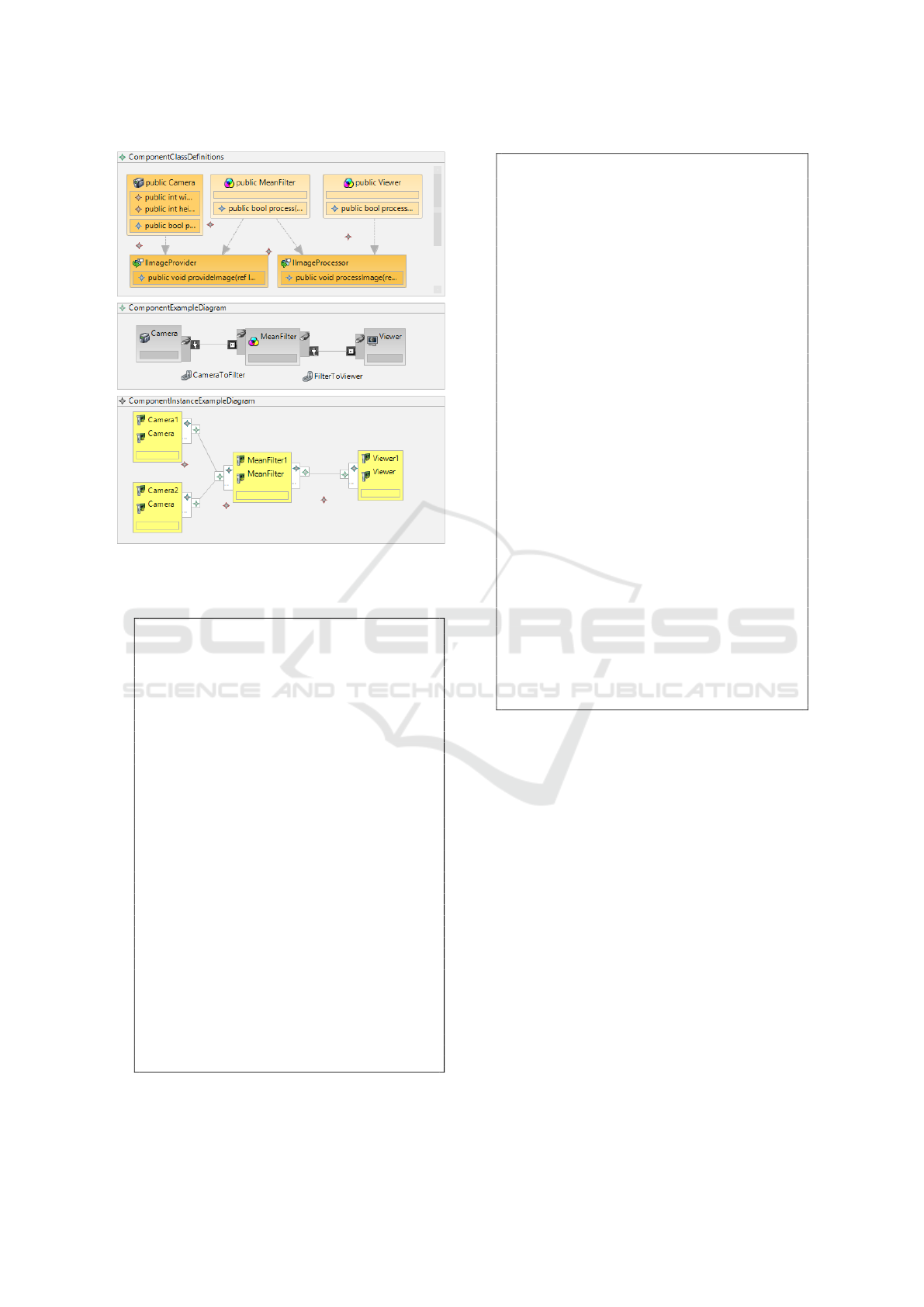
Figure 3: The graphical CBSE example. Top: The class
diagram; Middle: The component-diagram; Bottom: The
component-instance-diagram.
1 C ompo nent Diag ram C o mpon entEx ample Diag r am
2 {
3 s o u r c e C o m p o n e n t C l a s s D e f i n i t i o n s . Camera
4 { / / D e f i n e t h e o u t p u t p o r t
5 p o r t C a m e r a I m a g e P r o v i d e r P o r t ( p r o v i d e r
C a m e r a I m a g e P r o v i d e r P o r t :
6 C o m p o n e n t C l a s s D e f i n i t i o n s .
I I m a g e P r o v i d e r ) ;
7 / / De f i n e t h e p o r t
8 [ C a m e r a T o F i l t e r s o u r c e C a m e r a I m a g e P r o v i d e r P o r t .
C a m e r a I m a g e P r o v i d e r P o r t ==>
9 t a r g e t M e a n I m a g e P r o c e s s o r P o r t .
F i l t e r I m a g e P r o c e s s o r P o r t ]
10 }
11
12 f i l t e r C o m p o n e n t C l a s s D e f i n i t i o n s . M e a n F i l t e r
13 { / / D e f i n e t h e i n p u t and o u t p u t p o r t s
14 p o r t M e a n I m a g e P r o c e s s o r P o r t ( p r o c e s s o r
F i l t e r I m a g e P r o c e s s o r P o r t :
15 C o m p o n e n t C l a s s D e f i n i t i o n s .
I I m a g e P r o c e s s o r ) ;
16 p o r t M e a n I m a g e P r o v i d e r P o r t ( p r o v i d e r
F i l t e r I m a g e P r o v i d e r P o r t :
17 C o m p o n e n t C l a s s D e f i n i t i o n s .
I I m a g e P r o v i d e r ) ;
18
19 / / De f i n e t h e p o r t
20 [ F i l t e r T o V i e w e r s o u r c e M e a n I m a g e P r o v i d e r P o r t .
F i l t e r I m a g e P r o v i d e r P o r t ==>
21 t a r g e t V i e w e r I m a g e P r o c e s s o r P o r t .
V i e w e r I m a g e P r o c e s s o r P o r t ]
22 }
23
24 s i n k C o m p o n e n t C l a s s D e f i n i t i o n s . Viewer
25 { / / D e f i n e t h e i n p u t p o r t
26 p o r t V i e w e r I m a g e P r o c e s s o r P o r t ( p r o c e s s o r
V i e w e r I m a g e P r o c e s s o r P o r t :
27 C o m p o n e n t C l a s s D e f i n i t i o n s .
I I m a g e P r o c e s s o r ) ;
28 }
29 }
Listing 9: Component example diagram.
1
2 C o m p on e n t I n s t a n ce D i a g r a m
Co m p on e n t I n s t a n ce E x am p l eD i a gr a m
3 {
4 Camera1 i n s t a n t i a t e s C o m p o n e n t C l a s s D e f i n i t i o n s .
Camera
5 ( w i d t h = 6 4 0 , h e i g h t = 4 8 0 )
6 {
7 C a m e r a 1 P r o v i d e r P o r t : C a m e r a I m a g e P r o v i d e r P o r t (
8 p r o v i d e r C a m e r a I m a g e P r o v i d e r P o r t =
I I m a g e P r o v i d e r ( ) ) ;
9
10 [ s o u r c e C a m e r a 1 P r o v i d e r P o r t .
C a m e r a I m a g e P r o v i d e r P o r t ==> t a r g e t
11 M e a n F i l t e r 1 . M e a n P r o c e s s o r P o r t .
M e a n I m a g e P r o c e s s o r P o r t ]
12 }
13
14 Camer a2 i n s t a n t i a t e s C o m p o n e n t C l a s s D e f i n i t i o n s .
Camera ( )
15 {
16 C a m e r a 2 P r o v i d e r P o r t : C a m e r a I m a g e P r o v i d e r P o r t (
17 p r o v i d e r Ca m e r a I m a g e P r o v i d e r P o r t = I I m a g e P r o v i d e r
( ) ) ;
18
19 [ s o u r c e C a m e r a 2 P r o v i d e r P o r t .
C a m e r a I m a g e P r o v i d e r P o r t ==> t a r g e t
20 M e a n F i l t e r 1 . Me a n P r o c e s s o r P o r t .
M e a n I m a g e P r o c e s s o r P o r t ]
21 }
22
23 M e a n F i l t e r 1 i n s t a n t i a t e s C o m p o n e n t C l a s s D e f i n i t i o n s .
M e a n F i l t e r ( )
24 {
25 M e a n P r o c e s s o r P o r t : Me a n I m a g e P r o c e s s o r P o r t (
26 p r o v i d e r Me a n I m a g e P r o c e s s o r P o r t = I I m a g e P r o c e s s o r
( ) ) ;
27
28 M e a n P r o v i d e r P o r t : M e a n I m a g e P r o v i d e r P o r t (
29 p r o v i d e r Me a n I m a g e P r o v i d e r P o r t = I I m a g e P r o c e s s o r
( ) ) ;
30
31 [ s o u r c e M e a n P r o v i d e r P o r t . M e a n I m a g e P r o v i d e r P o r t ==>
t a r g e t
32 Viewe r 1 . V i e w e r P r o c e s s o r P o r t .
V i e w e r I m a g e P r o c e s s o r P o r t ]
33 }
34
35 Viewer1 i n s t a n t i a t e s C o m p o n e n t C l a s s D e f i n i t i o n s .
Viewe r ( )
36 {
37 V i e w e r P r o c e s s o r P o r t : V i e w e r I m a g e P r o c e s s o r P o r t (
38 p r o v i d e r V i e w e r I m a g e P r o c e s s o r P o r t =
I I m a g e P r o v i d e r ( ) ) ;
39 }
40 }
Listing 10: Component instance example diagram.
They propose concepts and patterns how elec-
tronic and software components of a robot can inter-
act and how they can be designed in a reusable way.
Furthermore, they introduce concepts of event driven
communication and also model driven approaches
(Schlegel et al., 2009).
In 2002, the CORBA Component Model (CCM)
(OMG, 2015b), based on CORBA 3.0, has been re-
leased supporting component based distributed archi-
tectures and services.
Another widely spread approach of component
based architectures is Microsoft’s Component Object
Model (COM) and its distributed version (DCOM)
(Microsoft, 2015). It is mostly language independent
using instantiable interfaces for an abstract view of
distributed components.
(Hoegg et al., 2015) introduce an image process-
ing C++ CBSE system. Using a code generator, GU-
DSL can be translated into this kind of component
framework.
In contrast to the mentioned languages and com-
Abstracting Data and Image Processing Systems using a Component-based Domain Specific Language
299

ponent systems, GU-DSL and its infrastructure pro-
vides the full functionality necessary for developing
interactive image processing pipelines. Furthermore,
the DSL supports the concept of round-trip engineer-
ing necessary for arbitrary switching between graphi-
cal and textual modeling. It specially focuses on ob-
ject oriented textual and graphical modeling in the
sense of model driven engineering. Starting with ob-
ject abstractions (from object to class to component)
up to the final system generation in the future, the full
development process can be assisted.
Besides the presented ADLs, frameworks and
concepts, many other systems exist, e.g. LabView
(Instruments, 2015) with its dataflow visual program-
ming language. But as far as we know, no language
exists which is comparable to the proposed one in the
domain of data and image processing.
6 CONCLUSION
In this paper we presented GU-DSL, a component
based textual and graphical language. GU-DSL uses
some well known design principles as classes, inter-
faces and components. These principles are adapted
and improved to fit into the domain of data and im-
age processing. We discussed all the novel fea-
tures and concepts (provider and processor inter-
faces, components, ports, component-instances and
also component- and component-instance-diagrams)
allowing the architecture definition and instantiation.
Furthermore, we have demonstrated their usage in an
image processing example.
A big advantage of the proposed work, compared
to other concepts (such as UML), is the combination
between graphical and textual modeling and the sup-
ported round-trip engineering. This means that both
kinds of modeling are always synchronized in both
directions. Starting with textual modeling does not
prevent developers from switching over to graphical
modeling and also back. So it is up to the modeler’s
and programmer’s preferences which kind of tech-
nique is used. Experienced programmers can decide
for textual programming, enjoying the full feature set
necessary for component-based engineering with the
advantage of much better guidance and support than
generic programming languages provide.
For the future, we plan to extend the graphical ed-
itors by a better and more complete toolbox (required
for graphical object creation). Also, the usability has
to be improved. Furthermore, the support of operat-
ing systems other than Windows is planned for the
language infrastructure and a code generator for C++
CBSE system has to be developed.
ACKNOWLEDGEMENTS
This work was supported by the German Research
Foundation (DFG) as part of the research training
group GRK 1564 ’Imaging New Modalities’.
REFERENCES
Allen, R. and Garlan, D. (1997). A formal basis for architec-
tural connection. ACM Trans. Softw. Eng. Methodol.,
6(3):213–249.
Efftinge, S., Eysholdt, M., Khnlein, J., Zarnekow, S., and
Contributors. (2015). Xtext 2.5 documentation.
Feiler, P. H., Lewis, B., Vestal, S., and Colbert, E. (2005).
An overview of the sae architecture analysis & design
language (aadl) standard: A basis for model-based
architecture-driven embedded systems engineering.
In Architecture Description Languages, volume 176,
pages 3–15. Springer US.
Fowler, M. (2010). Domain Specific Languages. Addison-
Wesley Professional, 1st edition.
Hoegg, T., Koehler, C., and Kolb, A. (2015). Component
based data and image processing systems - a concep-
tual and practical approach. In Software Engineering
and Service Science (ICSESS), 2015 6th IEEE Inter-
national Conference on, pages 66–69.
Instruments, N. (2015). Ni labview. Available at
http://www.ni.com/labview/.
Magee, J., Dulay, N., and Kramer, J. (1993). Structuring
parallel and distributed programs. Software Engineer-
ing Journal, 8:73–82.
Microsoft (2015). Component object model (com). Avail-
able at https://msdn.microsoft.com.
OMG (2015a). Corba. Available at http://www.corba.org/.
OMG (2015b). Corba component model. Available at
http://www.omg.org/spec/CCM.
OMG (2015c). Metaobject facility (mof). Available at
http://www.omg.org/mof/.
OMG (2015d). Ocl. Available at
http://www.omg.org/spec/OCL/.
OMG (2015e). Uml. Available at http://www.uml.org/.
OMG (2015f). Uml. Available at
http://www.omgsysml.org/.
Schlegel, C., Hassler, T., Lotz, A., and Steck, A. (2009).
Robotic software systems: From code-driven to
model-driven designs. In Advanced Robotics, 2009.
ICAR 2009. International Conference on, pages 1–8.
Schlegel, C. and Wrz, R. (1999). Interfacing different lay-
ers of a multilayer architecture for sensorimotor sys-
tems using the object-oriented framework smartsoft.
In Advanced Mobile Robots, 1999. (Eurobot ’99) 1999
Third European Workshop on, pages 195–202.
MODELSWARD 2016 - 4th International Conference on Model-Driven Engineering and Software Development
300
