
Feasibility Study of Inertial Sensor-based Joint Moment Estimation
Method During Human Movements
A Test of Multi-link Modeling of the Trunk Segment
Takashi Watanabe
1
and Jun Kodama
2
1
Dept. Biomedical Engineering, Graduate School of Biomedical Engineering, Tohoku University, Sendai, Japan
2
Dept. Electronic Engineering, Graduate School of Engineering, Tohoku University, Sendai, Japan
Keywords: Joint Moment, Inertial Sensor, Trunk, Rigid Body Link Model.
Abstract: The conventional method of estimating joint moments needs kinematic data measured with a 3D optical
motion measurement system and ground reaction forces measured with force plate. However, the
conventional method is limited generally to laboratory use because of the required measurement systems.
Therefore, we proposed a convenient method to estimate joint moments from measurements only with
inertial sensors for application to clinical evaluation of motor function of paralyzed and elderly subjects. In
this paper, multi-link modeling of the trunk was examined for reliable estimation of joint moments only
from measured data with inertial sensors attached on the body. Body segment parameters (segment length
and mass, center of mass location and moments of inertia) were calculated from anthropometric data.
Experimental test with 3 healthy subjects showed that segmented trunk model estimated joint moments
better than a rigid trunk model for squat and sit-to-stand movements. The estimation results were not
different largely between the 5-link model that modeled the trunk by 3 segments and the 4-link model that
modeled the trunk by 2 segments. However, trunk modeling for 4-link model was suggested to be
appropriate when the upper and the middle trunk segments of the 5-link model were modeled as one
segment.
1 INTRODUCTION
Difficulty in standing up is one of important factors
of preventing independent daily life for elderly or
motor disabled subjects. Joint moments during sit-
to-stand movement can evaluate decrease of muscle
force of lower limbs, from which a cause of the
difficulty in standing up can be estimated. However,
joint moments can not be measured directly with
sensors or measurement equipments, especially
during human movements. Therefore, generally,
joint moments are estimated by indirect means from
data measured with a camera based 3D motion
analysis system and a force plate system. However,
using these systems limits measurement
environment, especially to laboratory, and takes
many costs.
In our previous study, a method of estimating
joint moment only using inertial sensors was
proposed and shown to be feasible in our
preliminary test (Mori and Watanabe, 2011;
Watanabe et al., 2012). Although the proposed
method can remove the limitation of measurement
environment and reduce the cost, estimated joint
moments showed large difference in comparison
with the conventional method using 3D motion
analysis system and force plate. In addition, our
preliminary test suggested that 3-link model of the
body, which modeled the trunk as one segment, can
decrease the difference between inertial sensor based
moment estimation method and the conventional
method in comparison with 4-link model, which
modeled the trunk by 2 segments (Mori and
Watanabe, 2011). However, Zijlstra and Bisseling
reported that segmented trunk model estimated hip
abduction moment using acceleration and angular
velocity signals better than rigid trunk model
(Zijlstra and Bisseling, 2004).
Therefore, this paper aimed at reexamining the
feasibility of joint moment estimation only using
inertial sensors. Especially, in this paper, multi-link
models of the trunk were tested in estimation of joint
moments only from measured data with inertial
sensors attached on the body. Body segment
248
Watanabe, T. and Kodama, J.
Feasibility Study of Inertial Sensor-based Joint Moment Estimation Method During Human Movements - A Test of Multi-link Modeling of the Trunk Segment.
DOI: 10.5220/0005747902480255
In Proceedings of the 9th International Joint Conference on Biomedical Engineering Systems and Technologies (BIOSTEC 2016) - Volume 4: BIOSIGNALS, pages 248-255
ISBN: 978-989-758-170-0
Copyright
c
2016 by SCITEPRESS – Science and Technology Publications, Lda. All rights reserved
parameters (segment length and mass, center of
mass location and moment of inertia) were
calculated from anthropometric data reported by Ae
et al., (1992) and Kouchi and Mochimaru (2005).
Since there were several definitions of trunk
segmentation, based on the model used by Young et
al., (1983), 5-link model consisted of 3-trunk
segments, 2 types of 4-link model including 2 trunk
segments and 3-link model that uses rigid trunk
model were examined in joint moment estimation
comparing to reference data of joint moment
estimated by the conventional method.
2 ESTIMATION METHOD OF
JOINT MOMENTS
2.1 Rigid Body Link Model
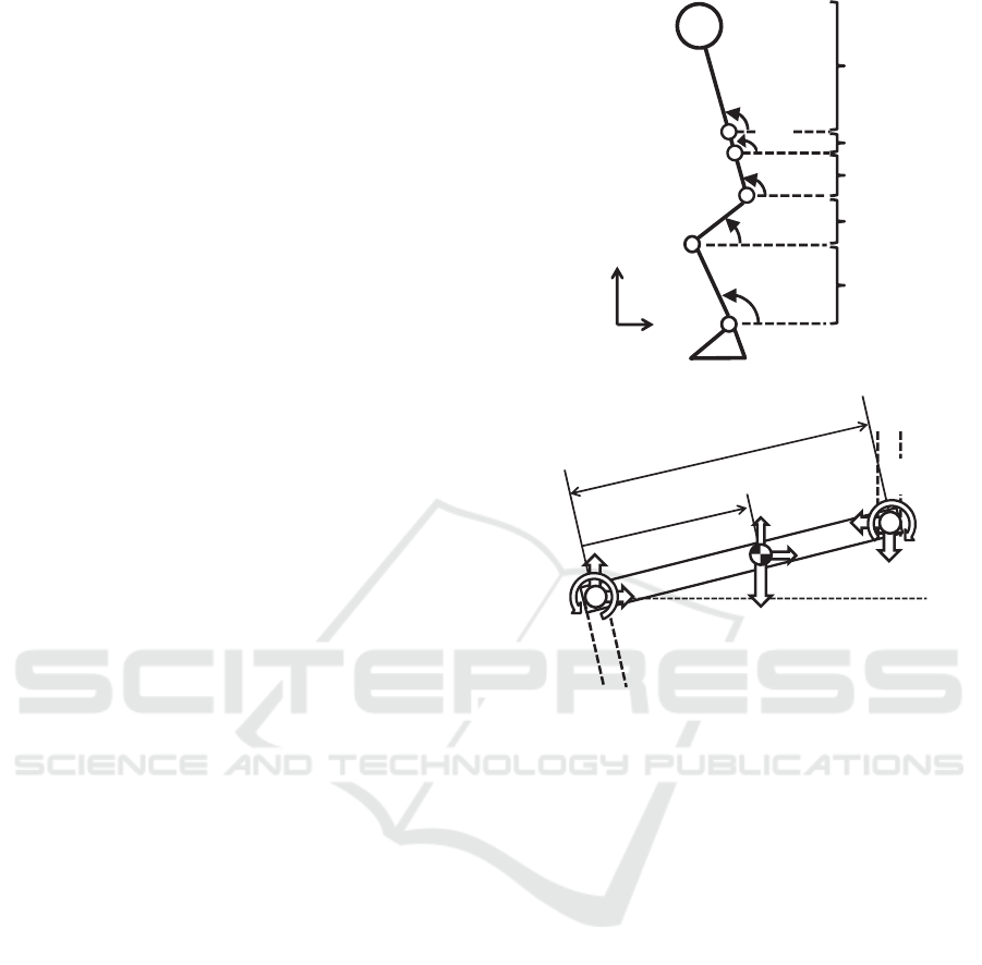
Figure 1(a) shows the rigid body link model for
human body (5-link model), which consists of the
shank (i=1), the thigh (i=2), the lower trunk (i=3),
the middle trunk (i=4) and the upper trunk (i=5). The
foot was fixed on the ground. Definition of
inclination angle of each segment for the 5-link
model is also shown in Figure 1(a). Each segment
was assumed to move in the sagittal plane. The
boundaries between the middle and the lower trunk
segments and between the upper and the middle and
trunk segments were defined at the highest point of
the iliac crest and the lower end of the rib,
respectively. Here, head and upper limbs were
included into the upper trunk segment.
The anthropometric data reported by Ae et al.,
(1992) used the model that segmented the trunk by
the lower end of the rib. For this modeling, the 4-
link model that segmented the trunk by the lower
end of the rib was defined (4-link-A-model). As
another 4-link model, trunk modeling segmented by
the highest point of the iliac crest was also defined
(4-link-B-model). Here, the lower trunk by Ae et al.,
(1992) means the middle-lower trunk of the 5-link
model. Therefore, body segment parameters of the
lower trunk of the 5-link and the 4-link-B models
were calculated from those of the lower trunk
reported by Ae et al., (1992), in which the middle
trunk was approximated by an elliptic cylinder with
the density reported by Clauser et al., (1969). Then,
body segment parameters for the upper-middle trunk
segment were calculated by synthesizing those of the
upper and the middle trunk segments. Size
parameters in calculation of the synthesizing were
obtained from average values in the AIST Human
body size database (Kouchi and Mochimaru, 2005).
(a) Inclinatoin angles
(b) joint reaction force and joint moment of segment i
Figure 1: Definitions of segment inclination angle, joint
reaction force and joint moment. a, b and c shows the
lower end of the rib, the highest point of the iliac crest and
the great trochanter, respectively.
2.2 Estimation of Joint Moment
Center of mass location of each segment was
calculated at first. Each segment length was
calculated from measured height of each subject by
using statistically obtained segment length ratio
(Kouchi and Mochimaru, 2005). The center of
segment mass locations of body segments were
calculated from measured inclination angles of
segments and the calculated segment lengths.
Acceleration of the center of mass and angular
acceleration of inclination angle of each segment
that were required in estimation of joint moments
were calculated by the differential using third order
low pass differentiation algorithm (Usui and Ikegaya,
1978).
Based on Figure 1(b), equations of translational
motion and rotational motion of the center of mass
of each rigid body segment are shown by the
followings:
i=1
i=2
i=3
i=4
i=5
θ
1
θ
2
θ
3
θ
5
X
Z
θ
4
c
b
a
l
i
r
i
l
i
F
z
i
M
i
θ
i
F
x
i
m
i
g
F
x
i+1
F
z
i+1
X
G
i
..
Z
G
i
..
M
i+1
Feasibility Study of Inertial Sensor-based Joint Moment Estimation Method During Human Movements - A Test of Multi-link Modeling of
the Trunk Segment
249
1
ii
xxGii
FFXm
(1)
gmFFZm
izzGii
ii
1
(2)
iizizi
iixixiiiii
lFrFr
lFrFrMMI
ii
ii
cos))1((
sin))1((
1
1
1
(3)
Here,
i : segment number
i
m
: segment mass
i
l
: segment length
i
r
: center of mass ratio from the lower end
i
I
: moment of inertia
i
M
: joint moment
i
x
F
,
i
z
F
: joint reaction forces
Gi
X
,
Gi
Z
: acceleration of segment center of mass
position
i
,
i
: inclination angle and its angular acceleration
g : gravitational acceleration
Joint reaction forces are calculated from Equations
(1) and (2), and then values of the forces are
substituted in Equation (3). Each joint moment can
be estimated by solving these simultaneous
equations with the assumption that no external force
acts to the upper segment.
3 EXPERIMENTAL METHODS
Figure 2 shows experimental set up. In order to
examine the joint moment estimation method,
human movements were measured with optical 3D
motion measurement system (OPTOTRAK,
Northern Digital), force plate (9286A, Kistler) and
wireless inertial sensors (bluetooth, InvenSense
MPU-9150, ERi). Three healthy subjects (male, 21-
23 y.o.) performed 5 times of 4 movements: 2 types
of squat movement (movement time was 6s and 9s)
and 2 types of sit-to-stand movement (normal and
forward inclination of the trunk imitating elderly
persons).
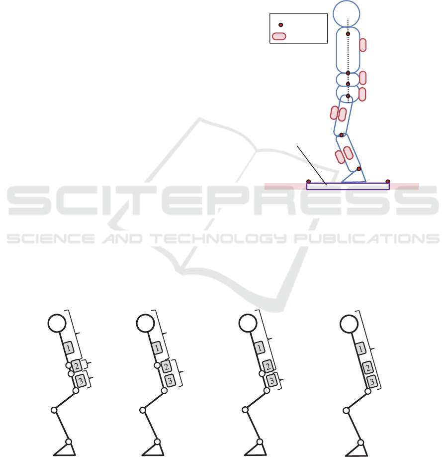
Figure 2: Experimental setup of measurement of
movement with inertial sensors, 3D motion measurement
system and force plate.
Inertial sensors were attached on the skin with
double-sided adhesive tape near the center of mass
location to the front and the lateral sides of the shank
and the thigh of left lower limb, and the back side at
upper, middle and lower trunk segments as shown in
Figure 3: Multi-link models tested in this paper and sensor attachment positions to the trunk segments. 1, 2 and 3 shows
inertial sensors, and a, b and c shows the lower end of the rib, the highest point of the iliac crest and the great trochanter,
respectively.
s1
s2
s3
s5
s4
s6
s7
: marker
: sensor
force plate
3-link
4-link-B
4-link-A
trun
k
upper-middle
lower
middle-lower
upper
5-link
upper
middle
lower
a
c
b
a
c
c
b
c
BIOSIGNALS 2016 - 9th International Conference on Bio-inspired Systems and Signal Processing
250

Figure 2. Markers for the 3D motion measurement
system were attached on the left side of subject, in
which positions were the acromion, along the long
axis of the trunk at the same height as the lower end
of the rib and the highest point of the iliac crest, the
great trochanter, the lateral femoral condyle, and the
lateral malleolus.
Figure 3 shows sensor attachment to trunk
segments of each link model. Reference moment
data were calculated by the conventional method
from measured data with 3D motion measurement
system and force plate for each link model.
Inclination angles were obtained by calculating
the integral of measured angular velocity with
inertial sensor, in which integrated errors caused by
offset of gyroscope was removed assuming constant
offset value during movement. The measured
inclination angles with inertial sensors and estimated
joint moments were evaluated for movement period
that were detected by angular velocity of the shank
for squat movement and by ground reaction force for
sit-to-stand movement, respectively.
4 RESULTS
4.1 Inclination Angles
Segment inclination angles measured with inertial
sensors were compared to those angles measured
with 3D motion measurement system. Calculation
error of the angle by the integral of angular velocity
was corrected by linear approximation of the integral
error. Figure 4 shows average RMS (root mean
square) errors of angles between inertial sensor and
3D motion measurement system. For inclination
angles of the shank and the thigh segments, sensors
attached to the lateral side showed lower values of
RMS error than those of sensors attached to the front
side. For the angles of trunk segment of the 3-link
model, the sensors 1 and 2 that were attached to the
upper and the middle trunks showed small RMS
errors, although the sensors 2 showed the lowest
errors. For angles of the middle-lower trunk segment
of the 4-link-A model, sensor 3 attached to the lower
trunk showed smaller RMS errors. Sensor 1 attached
to the upper trunk showed smaller RMS errors for
angles of the upper-middle trunk segment of the 4-
link-B model.
Figure 4: RMS values of segment inclination angles measured with inertial sensors and the 3D motion measurement system.
s1, s2 and s3 show sensors attached to the trunk shown in Figures 3 and 4. RMS values were calculated for shank and thigh
segments, and a rigid trunk segment of 3-link model, and upper (U-T), middle (M-T), lower (L-T), upper-middle (UM-T)
and middle-lower (ML-T) trunk segments of 4-link and 5-link models.
0
5
10
15
20
25
shank thigh
front
lateral
0
5
10
15
20
25
0
5
10
15
20
25
0
5
10
15
20
25
0
5
10
15
20
25
RMS error [deg]
RMS error [deg]
RMS error [deg]
RMS error [deg]
RMS error [deg]
(a) lower limb (b) 3-link
(c) 4-link-A (d) 4-link-B (c) 5-link
ML-T
s3 s2
U-T
s1 s2
UM-T
s1
s3 s2 s1
L-T
s3
s3 s2 s1
U-T
L-T
M-T
Feasibility Study of Inertial Sensor-based Joint Moment Estimation Method During Human Movements - A Test of Multi-link Modeling of
the Trunk Segment
251
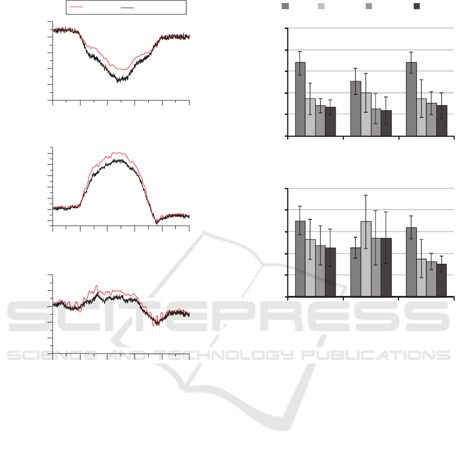
Figure 5: Examples of estimated and reference joint
moments during squat movement (5-link model).
From above results, sensors that showed the
lowest RMS errors were used for measurement
inclination angles of segments in joint moment
estimation.
4.2 Joint Moment
Joint moments were estimated by using inclination
angles measured with inertial sensors determined in
the previous section. Figure 5 shows examples of
estimated and reference joint moments during squat
movement with the 5-link model. Estimated
moments were normalized to the weight of subject.
The inertial sensor based joint moment estimation
method was suggested to estimate joints moments
appropriately.
RMS values of differences between reference
Figure 6: RMS values of estimated joint moments only
with inertial sensors.
moment data and the estimated moments were
shown in Figure 6. For squat movement, the RMS
values of the 5-link model were the smallest and the
4-link-B model showed similar RMS values as those
of the 5-link model, which were less than 0.1 Nm/kg
in average. Although the 4-link-A model showed
smaller RMS values than those of the 3-link model,
the average value and variations were larger than
those of the 5-link and 4-link-B models. RMS values
of the estimated moments shown in Figure 6 were
0.098, 0.112 and 0.074 for the hip, knee and ankle
joints, respectively. For sit-to-stand movement,
estimation of ankle and hip joint moments showed
similar results as the squat movement. However,
knee joint moment was estimated well by the 3-link
model.
In order to validate the estimation method,
inclination angles measured with 3D motion
measurement system were substituted for the angles
in Equations (1)-(3) and joint moments were
estimated by the estimation method described in
Section 2.2 without ground reaction forces. The
0246810
-0.8
-0.6
-0.4
-0.2
0.0
0.2
0246810
0.0
0.2
0.4
0.6
0.8
1.0
1.2
0246810
-0.8
-0.6
-0.4
-0.2
0.0
0.2
sensor
reference
moment [Nm/kg]moment [Nm/kg]moment [Nm/kg]
(a) hip joint
(b) knee joint
(c) ankle joint
[s]
[s]
[s]
0
0.05
0.1
0.15
0.2
0.25
ankle knee hip
RMS value [Nm/kg]
3link 4link-A 4link-B 5link
0
0.05
0.1
0.15
0.2
0.25
ankle knee hip
RMS value [Nm/kg]
(a) squat
(b) sit-to-stand
BIOSIGNALS 2016 - 9th International Conference on Bio-inspired Systems and Signal Processing
252
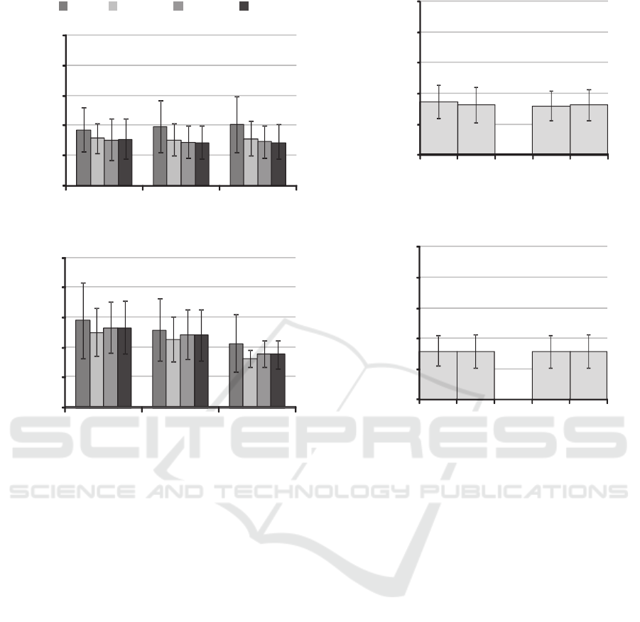
Figure 7: RMS values of estimated joint moments using
inclination angles measured with the 3D motion
measurement system and no ground reaction forces.
results were also compared to the reference moment
data as shown in Figure 7. Although 3-link model
showed the largest RMS values for both movements,
most of the values were smaller than those of
estimation with inertial sensor signals. For the squat
movement, similar results were obtained as the
results with inertial sensors. Although the 4-link-A
model showed smallest RMS values for sit-to-stand
movement, the differences from those of the 5-link
and 4-link-B model were not so large.
The results of Figures 6 and 7 suggest that the 4-
link and the 5-link models could estimate joint
moment better than 3-link model. However, RMS
values of the knee joint moment and some variations
of RMS values were larger and than those of the 3-
link model for the sit-to-stand movement with
inertial sensors.
The 4-link and the 5-link models can estimate
joint moments at the joint between trunk segments.
Estimated joint moments of trunk segments were
compared to the results calculated by the
conventional method. RMS values were shown in
Figure 8: RMS values of trunk joints moments estimated
without ground reaction force. 4A, 4B, 5 represents link
model. Waist and abdominal mean joints between the
middle and the lower trunk segments (at the highest point
of the iliac crest) and between the upper and the middle
trunk segments (at the lower end of the rib), respectively.
Figure 8. RMS Values of joint moments of trunk
segments were similar to those of the hip joint
moment estimation, which were less than 0.1 Nm/kg.
These results were almost same between the 4-link
and 5-link models. Segment inclination angles
measured with 3D motion measurement system also
showed similar results with the inertial sensor based
method.
5 DISCUSSIONS
For measurement of inclination angle of lower limb
with inertial sensors, sensors attached to the lateral
side showed smaller RMS errors than those of
sensors attached on the front side as shown in Figure
4(a). In our previous study, inclination angles of
lower limb segments measured with inertial sensors
0
0.05
0.1
0.15
0.2
0.25
ankle knee hip
0
0.05
0.1
0.15
0.2
0.25
ankle knee hip
RMS value [Nm/kg]
RMS value[Nm/kg]
(a) squat
(b) sit-to-stand
3link 4link-A 4link-B 5link
0
0.05
0.1
0.15
0.2
0.25
RMS value [Nm/kg]
0
0.05
0.1
0.15
0.2
0.25
RMS value [Nm/kg]
4A
waist
54B
abdominal
5
4A
waist
54B
abdominal
5
(a) inertial sensors
(b) 3D motion analysis system
Feasibility Study of Inertial Sensor-based Joint Moment Estimation Method During Human Movements - A Test of Multi-link Modeling of
the Trunk Segment
253

attached to the front side during walking showed
RMS errors less than about 4deg in average in
comparison with the 3D motion measurement
system. The measurements performed in this paper
were during squat and sit-to-stand movements that
involve large hip and knee flexion movements,
which were different from waking. Those large
flexion movements were considered to cause
differences in measurement results between sensors
and markers. That is, deformation of muscles and
sitting on the stool before standing up are considered
to move markers and sensors differently.
As for the trunk inclination angles, 4-link-B
model showed the smallest RMS errors as shown in
Figure 4. Sensor 1 could measure inclination angles
of the upper trunk and the upper-middle trunk with
small RMS values. This suggests that movements of
the upper and the middle trunks are similar even in
the squat and the sit-to-stand movements. Therefore,
4-link-B model that uses the upper-middle trunk
segment is considered to be appropriate. Although
RMS values of the middle trunk of 5-link model was
large, there was a possibility that angle measurement
with the 3D motion measurement system (markers
on the highest point of the iliac crest and the lower
end of the rib) were affected by movements of skin
or subcutaneous fat tissue during trunk bending
movement.
The 5-link and the 4-link-B models showed
similar good RMS values of joint moment
estimation. The 4-link-A model showed increase of
variation of RMS values of hip joint moment for
both movements and ankle joint moment for squat
movement, and the largest RMS values of the knee
joint moment for the sit-to-stand movement in
estimation with inertial sensors. On the other hand,
validation test of the joint moment estimation
method shown in Figure 7 suggested that the 5-link
and 4-link models can estimate joint moments with
similar RMS value. The deterioration of the 4-link-A
model in moment estimation with inertial sensors is
considered to be caused by large difference in
inclination angle of the middle-lower trunk segment.
Variations of RMS values increased for sit-to-
stand movement as seen in Figures 6 and 7. The
variation was considered to be caused by differences
among subjects. Error in modeling subject by rigid
body link model is considered to be caused by using
anthropometric data that were statistic average
values. That is, physical constitution of each subject
was different from average.
RMS values in joint moment estimation with
inertial sensors were less than 0.1 and o.15 for squat
and sit-to-stand movements, respectively. As shown
in Figures 6 and 7, the 5-link and the 4-link-B
models with inertial sensors showed similar RMS
values in joint moment estimation with the 3D
motion measurement system and no ground reaction
forces. These suggest that the method of joint
moment estimation using inertial sensors in this
paper is feasible. However, further studies are
required to make clear if the RMS values are
acceptable or not, increasing the number of subjects.
Joint moment estimation of trunk segments
showed similar RMS values as those of the hip joint
moment. It is considered that this is because
moments of trunk segments were similar values as
those of the hip joint, since the segment masses and
lengths of the middle and the lower trunk segments
were smaller and shorter than those of the upper
trunk segment.
6 CONCLUSIONS
This paper aimed at determination of feasibility of
the method of estimating joint moment only using
inertial sensors. Multi-link model of the trunk was
tested in joint moment estimation after calculations
of body segment parameters based on
anthropometric data. The proposed method could
estimate similar waveform of joint moments as those
of the conventional method. Segmented trunk model
estimated joint moment better than a rigid trunk
model. The estimation results were not different
between the 5-link model that modeled the trunk by
3 segments and the 4-link model that modeled the
trunk by 2 segments. However, trunk modeling for
4-link model was found to be appropriate when the
upper and the middle segments were modeled as one
segment in case of using inertial sensors. The results
of this paper suggested that the inertial sensor based
joint moment estimation is feasible. Further tests are
expected to improve reliability of the inertial sensor
based joint angle estimation method.
ACKNOWLEDGEMENTS
This work was supported in part by the Ministry of
Education, Culture, Sports, Science and Technology
of Japan under a Grant-in-Aid for challenging
Exploratory Research.
BIOSIGNALS 2016 - 9th International Conference on Bio-inspired Systems and Signal Processing
254

REFERENCES
Ae, M., Tang, H.-P., Yokoi, T., 1992. Estimation of Inertia
Properties of the Body Segments in Japanese Athletes,
Biomechanisms 11, pp.23-33. (in Japanese).
Clauser, C. E., McConville, J. T., Young, J. W., 1969.
Weight, volume, and center of mass of segments of the
human body, AMRL Technical Report TR, pp.69-70.
Kouchi, M, Mochimaru, M., 2005. AIST Human Body
Measurement Database 1991-92. https://www.dh.aist.
go.jp/database/91-92. (in Japanese).
Mori, H., Watanabe, T., 2011. A Study on Measurement
of Moment of Lower limb Using Wearable Sensors.
Proc. 32th Annual Conference of Biomechanisms of
Japan, pp.91-94 (in Japanese).
Teruyama, Y., Watanabe, T., 2013. Effectiveness of
variable-gain Kalman filter based on angle error
calculated from acceleration signals in lower limb
angle measurement with inertial sensors.
Computational and mathematical methods in medicine,
Vol.2013, Article ID 398042, 12 pages.
Usui, S, Ikegaya, K., 1978. Low Order Low-Pass
Differential Algorithm for Data Processing and Its
Evaluation, The transactions of the Institute of
Electronics and Communication Engineers of Japan,
Vol.J61-D, No.11, pp.850-857. (in Japanese).
Watanabe, T., Mori, H., Suzuki, T., 2012. A Preliminary
Test of Lower Limb Joint Moment Estimation Method
without Ground Reaction Force using Inertial Sensors.
In ABSTRACT BOOK, 34th Annual Conference of
the IEEE EMBS, p.661.
Young, J. W., Chandler, R. F., Snow, C. C., Robinette, K.
M., Zehner, G. F., Lofberg, M. S., 1983.
Anthropometric and mass distribution characteristics
of the adult female. Technical Report No. FAA-AM-
83-16.
Zijlstra, W., Bisseling, R., 2004. Estimation of hip
abduction moment based on body fixed sensors.
Clinical Biomechanics, Vol.19, pp.819-827.
Feasibility Study of Inertial Sensor-based Joint Moment Estimation Method During Human Movements - A Test of Multi-link Modeling of
the Trunk Segment
255
