
A Practical Framework for the Development of Augmented Reality
Applications by using ArUco Markers
Danilo Avola
1
, Luigi Cinque
2
, Gian Luca Foresti
1
, Cristina Mercuri
2
and Daniele Pannone
2
1
Department of Mathematics and Computer Science, University of Udine, Via delle Scienze 206, 33100 Udine, Italy
2
Department of Computer Science, Sapienza University of Rome, Via Salaria 113, 00198 Rome, Italy
Keywords:
Augmented Reality, ArUco Marker, OpenCV, OpenGL.
Abstract:
The Augmented Reality (AR) is an expanding field of the Computer Graphics (CG) that merges items of the
real-world environment (e.g., places, objects) with digital information (e.g., multimedia files, virtual objects) to
provide users with an enhanced interactive multi-sensorial experience of the real-world that surrounding them.
Currently, a wide range of devices is used to vehicular AR systems. Common devices (e.g., cameras equipped
on smartphones) enable users to receive multimedia information about target objects (non-immersive AR).
Advanced devices (e.g., virtual windscreens) provide users with a set of virtual information about points of
interest (POIs) or places (semi-immersive AR). Finally, an ever-increasing number of new devices (e.g., Head-
Mounted Display, HMD) support users to interact with mixed reality environments (immersive AR). This
paper presents a practical framework for the development of non-immersive augmented reality applications
through which target objects are enriched with multimedia information. On each target object is applied a
different ArUco marker. When a specific application hosted inside a device recognizes, via camera, one of
these markers, then the related multimedia information are loaded and added to the target object. The paper
also reports a complete case study together with some considerations on the framework and future work.
1 INTRODUCTION
In the last few decades, AR has become one of the
emerging technologies both in academic research and
in field of industry. Travel-guide applications (Han
et al., 2013; Pendit et al., 2014), as well as those for
tourists (Chen, 2014; Kourouthanassis et al., 2015)
are probably the most widespread AR applications,
since their connection with AR technologies was im-
mediately evident. Despite this, also other fascinat-
ing fields are taking advantage by using these tech-
nologies. In robotics, for example, AR is used to ad-
dress different challenges, from the development of
systems that allow operators to program actions and
events (Pettersen et al., 2003), up to the implementa-
tion of novel interfaces for interactive robot path and
end-effector orientation planning (Fang et al., 2014).
The medical field is another context where an increas-
ing number of researchers is studying novel AR appli-
cations. Many of these applications concern the en-
hancement of the visualization of the organs and tis-
sues during laparoscopic surgical interventions (Choi
et al., 2015; Ferrari et al., 2015). Even within the
military field the AR is playing a main role for the
development of applications to coordinate defensive
operations (Jung et al., 2008) or support tactical tasks
(Kang and Lee, 2015). Different surveys of AR are
available in literature (Van-Krevelen and Poelman,
2010; Billinghurst et al., 2015).
In this multitude of remarkable studies and appli-
cations, our simple contribute is to provide a practi-
cal and manageable framework for the development
of non-immersiveAR applications through which tar-
get objects are enriched with multimedia informa-
tion. When the RGB sensor of the device (e.g., smart-
phone) recognizes the ArUco marker placed on an ob-
ject, then an image, a video, or the home page of a
Web site is projected on the marker. If the marker has
an unfavourable position or size, the multimedia in-
formation can be also projected elsewhere (near the
marker). One of the most important feature of an AR
application is the agreement between the movement
of the object into the real-world and the projected
multimedia information. This feature can assume a
huge importance in complex contexts, such as auto-
matic interaction or robotic surgery. Since the pro-
posed framework has been designed for general pur-
poses, it includes this feature. The projected infor-
Avola, D., Cinque, L., Foresti, G., Mercuri, C. and Pannone, D.
A Practical Framework for the Development of Augmented Reality Applications by using ArUco Markers.
DOI: 10.5220/0005755806450654
In Proceedings of the 5th International Conference on Pattern Recognition Applications and Methods (ICPRAM 2016), pages 645-654
ISBN: 978-989-758-173-1
Copyright
c
2016 by SCITEPRESS – Science and Technology Publications, Lda. All rights reserved
645

mation follow (when possible) orientation, scale and
size of the ArUco marker thus providing users with a
real feeling of mixed reality. Although the proposed
framework has been designed for non-immersive ap-
plications, it can be also considered to develop semi-
immersive and immersive applications.
The rest of the paper is structured as follows.
Section 2 discusses related work on the use of fidu-
cial markers to support AR applications. Section 3
introduces some different kinds of fiducial markers
and highlights which of them is more suitable to
implement AR applications. Section 4 provides an
overview of the architecture of the framework and
reports a complete case study. Section 5 includes
several experimental observations. Finally, Section 6
concludes the paper and draws future directions.
2 RELATED WORK
Although the widespread of both AR technologies
and marker based approaches, works regarding their
collaboration in some kind of application are less
common than expected. Moreover, there are not so
much works regarding the development of a frame-
work to simplify the process of generating dedicated
AR applications. Two of the main issues of this kind
of applications regard the recognition and tracking of
fiducial markers. In fact, the different inner patterns
that compose a wide range of markers are often used
to detect themselves instead of providing correspond-
ing feature points for pose accuracy. In this direction
several groups of researchers have proposed their own
contribute. A first interesting approach is presented
by (Li et al., 2007), their method utilizes directly the
projective invariant contained in the positional rela-
tion of the corresponding feature points to encode the
marker. Another interesting technique is introduced
by (Jung and Kim, 2012), where a domain-specific
marker recognition approach is proposed. A different
work that highlights how AR and fiducial markers can
collaborate to make interactive real-time applications
is shown by (Fahn et al., 2013). In their work, the au-
thors developed real-time visual tracking techniques
based on edge detection and made 3D virtual objects
display on a set of defined markers that were within
the source images in the Field of View (FoV) of the
camera. Like the previous one, the work proposed by
(Hagbi et al., 2011) shows an alternative way to create
fascinating AR applications by using a variant of the
markers. The authors present a system for real-time
recognition and camera pose estimation from planar
shapes. Their system allows shapes that carry contex-
tual meanings for humans to be used as AR tracking
fiducials. The recognition of each shape is performed
by analysing contour structures and generating pro-
jective invariant signatures from their concavities.
These and other experiences available in literature
have promoted the development of different kinds of
marker for the implementation of AR applications.
The next section introduces some consideration about
marker libraries and briefly outlines the reasons for
which we have chosen the ArUco markers.
3 BACKGROUND
As well-known, fiducial markers are stylized images
composed by a set of distinguishable patterns. Cur-
rently, these markers are used to support a real wide
range of practical applications. In some cases, for ex-
ample, they are adopted to simplify the recognition
process of moving objects or persons. In other cases,
they are utilized to guide moving robots or vehicles.
They are also used to encode a large amount of infor-
mation or, as in our context, to support AR applica-
tions. In any case, two types of information can be
distinguished inside a marker:
Recognition Data (R-Data): it is the part of the
marker that contains information to favour its
recognition within the real-world environment, in-
cluding size, orientation and distortion;
Information Data (I-Data): the rest of the marker
is composed of both data about the target object
on which the marker is applied and error codes
for the correction of this data.
In the left part of the Figure 1 three examples of
common fiducial markers are shown. The first one,
Data Matrix (Figure 1a), was designed for encoding
large amount of data characters. Originally, it was
developed for the Space Shuttle Program, where mil-
lions of parts had to be tracked. The second one,
MaxiCode (Figure 1b), was designed by UPS (United
Parcel Service) for sorting and addressing their pack-
ages. Finally, the QR Code (Figure 1c), was devel-
oped by DENSO WAVE
1
for supporting different lo-
gistics operations. Despite their widespread, the use
of this kind of markers is not recommended to sup-
port AR applications. In fact, these markers have the
common feature that R-Data only fill a small portion
of their structures since the rest of the markers is de-
signed to contain a large amount of I-Data. For exam-
ple, within a Data Matrix marker the R-Data is rep-
resented both by the two solid borders (bottom and
left) and by the two dashed borders (up and right, al-
ternating black and white items). This R-Data pattern
1
http://www.qrcode.com/en/
ICPRAM 2016 - International Conference on Pattern Recognition Applications and Methods
646

(a) Data Matrix. (b) MaxiCode. (c) QR Code. (d) AR-ToolKit. (e) ARTag. (f) ArUco
Figure 1: Example of fiducial markers not suitable, (a)(b)(c), and suitable, (d)(e)(f), for the development of AR applications.
requires to be scanned closely for avoiding misinter-
pretations or ambiguity issues. Similar considerations
can be made for the other two markers, MaxiCode
and QR Code, whose R-Data pattern is represented by
the set of concentric circles and by the three squared
shapes, respectively.
A fiducial marker library suitable for the develop-
ment of AR applications has to own some main prop-
erties:
The recognition of the marker has to be as inde-
pendent as possible from both the perspective and
the distance;
The marker has to contain a high amount of R-
Data and a low amount of I-Data. The only I-Data
of these markers should be the identification num-
ber (ID). The rest of the marker should be a sim-
ple R-Data pattern easily recognizable in different
non-collaborative contexts.
The next sub-sections show some examples of
fiducial markers (right part of the Figure 1) which are
compliant with the previous properties. In particular,
the role and the main properties of the ArUco markers
is briefly introduced.
3.1 AR-ToolKit
Among the different libraries used to build AR appli-
cations, AR-ToolKit
2
is probably one of the simplest
(Figure 1d). Each marker is composed by a squared
shape with black borders and a centred white area.
This last contains a black pattern that can be inher-
ited by the library or customized by users. The black
borders favour both the recognition of the marker and
the distinguishing between it and the internal pat-
tern. Usually, each marker contained within the AR-
ToolKit library has been acquired with different res-
olutions (e.g., light, distance) and different orienta-
tions (i.e., rotations). This process tends to favour
the recognition of markers both in outdoor environ-
ments and in real contexts. The black borders are de-
tected by using well-known binarization algorithms
(e.g., threshold, edge detection), while an affective
process of template matching is adopted to select the
2
http://www.hitl.washington.edu/artoolkit/
more correlated marker. All these aspects make the
AR-ToolKit library a fast and versatile tool. Despite
this, in our experiences, we have observed that an
increasing number of markers can provoke issues of
ambiguity and a high computational cost. Finally, the
recognition of customized markers can require a com-
plex process of training.
3.2 ARTag
Another library designed to build AR applications is
ARTag
3
Figure 1e). Also in this case each marker
is a squared shape, but the borders can be blacks or
whites and the internal pattern contains binary infor-
mation. More specifically, each marker is a matrix
of 10 × 10 items, where each border has a thickness
of 2 items and the internal pattern is a sub-matrix of
6× 6 items. In this way, each fiducial marker can ex-
press 36 bit of information subdivided in 10 bit for
the ID and 26 bit for the error codes. Unlike the AR-
ToolKit, the ARTag recognizes the boundaries of the
square using only an effective edge detection algo-
rithm (without using any threshold). This last aspect
allows ARTag both to recognize partially occluded
markers and to save time during the matching pro-
cess. Despite its remarkable features, the library is
not longer upgraded by its designers. Moreover, our
preliminary tests have highlighted some issues in rec-
ognizing markers in complex outdoor environments.
3.3 ArUco
We have chosen the ArUco
4
markers (Figure 1f) since
they meet all our requirements in terms of robust-
ness, reliability and versatility (Garrido-Jurado et al.,
2014). Moreover, their recognition is very fast with a
low level of ambiguity in indoor environments. As for
the previous libraries, the recognition of the ArUco
markers in outdoor environments is a hard task. This
last aspect is crucial for this kind of systems. Finally,
the ArUco library is free for research purposes and it
has been recently included within the last stable ver-
3
http://www.artag.net/
4
http://www.uco.es/investiga/grupos/ava/node/26
A Practical Framework for the Development of Augmented Reality Applications by using ArUco Markers
647

sion of OpenCV 3.0
5
. Usually, an ArUco marker is
represented by a matrix of 7 × 7 items, where each
black border has a thickness of 1 item and the inter-
nal pattern is a sub-matrix of 5× 5 items. This means
that the internal pattern is composed of 5 rows each
of which with a length of 5 binary items (i.e., black or
white). The designers have employed a slight modi-
fication of the Hamming Code for the codification of
each marker, where 2 bits are used for the informa-
tion and 3 bits are used for the error detection. As
a consequence, it is possible to generate up to 1024
different markers. The main difference between the
original Hamming Code and their reformulation is
that the first bit (parity of bits 3 and 5) is inverted.
In this way, the first ArUco marker (i.e., the marker
with ID = 0) can be coded by 100000 with the novel
Hamming Code instead of 00000 with the original
one. The idea is to prevent a completely black rect-
angle from being a valid marker ID with the goal of
reducing the likelihood of false positives with objects
of the environment. The ArUco library is also inte-
grable with OpenGL
6
, which provides full support for
the development of AR applications. Beyond the per-
sonal experience, the selection of the ArUco library
has been also supported by different works available
in literature which show its practicality and effective-
ness (Speers et al., 2011; Pestana et al., 2014; Babinec
et al., 2014; Sanchez-Lopez et al., 2014).
4 THE FRAMEWORK
ARCHITECTURE
The frameworkarchitecture (Figure 2) is composed of
three main modules. The first one, Camera Calibra-
tion, deals with the calibration of the device’s cam-
era. The second one, Processing Engine, deals with
the building of the AR applications, from the scene
acquisition up to the multimedia projection. The lat-
est, Code Generation, deals with the optimization of
the object code that will be installed on the device.
The framework is managed by a GUI which guides
the main interactive operations, including: the link-
ing between multimedia information and markers, the
setting of the camera calibration, and the insertion of
metadata.
4.1 Camera Calibration
The intrinsic calibration of a camera is a common task
of a wide range of computer vision applications. In
5
http://opencv.org/
6
https://www.opengl.org/
our context, this task has a huge importance since the
recognition process of the ArUco markers is a critical
aspect of the framework. The Camera Calibration is a
simple module based on OpenCV 3.0 by which users
can calibrate any kind of desktop or mobile device.
Once acquired the calibration video (i.e., a video of
a chessboard in various orientations) the framework
generates two XML files representing the parameters
of calibration (i.e., cameraMatrix) and the coefficients
of distortion (i.e., distCoeffs) of the device, respec-
tively (Zhang, 2000). In our empirical experience a
chessboard with (9, 6) inner angles where each square
has a side of 25mm is sufficient to support the cal-
ibration process of the most current devices. These
parameters are subsequently sent to the Code Gener-
ator which includes them inside each AR application
generated for that specific device. Note that, the cali-
bration process is an optional step designed to support
a better recognition of the markers in those particular
application contexts where it can be repeated on all
the devices used for a specific AR application.
4.2 Processing Engine
The Processing Engine is the module that deals with
the building of the AR applications. The pipeline
of this module is composed of five submodules each
aimed at generating a specific task of these applica-
tions during their running on the devices. Some of
these tasks are the same for each type of application,
others change, or are customized, according to the
type of application. Note that, in this work we con-
sider three classes of applications depending on the
kind of multimedia projected by the devices: image,
video, or home page of a Web site. The next subsec-
tions report the main aspects of these submodules.
4.2.1 Scene Acquisition
The task of this submodule is common to all the ap-
plications and performs two main functions. The first
one is to set a limit to the amount of the acquired
frames independently of the frame-per-second (fps)
of the devices. The second one is to resize each ac-
quired frame. Both functions are performed to re-
duce the computational overhead due to the activity
of the next submodule: Marker Detection. Although
these parameters can be managed by the GUI, in
our experience we have observed that the acquisition
of 20 fps each with a spatial resolution of 640x480
can be considered a suitable compromise between the
real-time execution and the natural interaction of the
users. Note that, current devices (e.g., laptops, tablets,
smartphones) differ greatly in computational capac-
ity, type of RGB camera, availability of RAM, and so
ICPRAM 2016 - International Conference on Pattern Recognition Applications and Methods
648
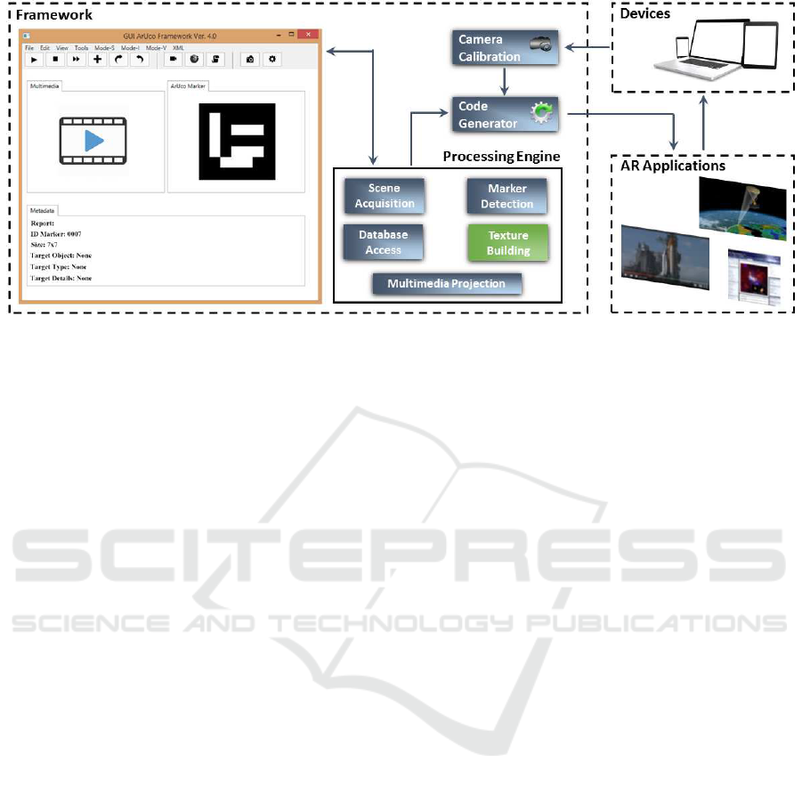
Figure 2: The Framework Architecture is composed of three main modules: the Camera Calibration that deals with the
calibration of the device’s camera; the Processing Engine that deals with the building of the AR applications; and the Code
Generator that deals with the optimization of the AR applications. The GUI manages the whole framework.
on. The comparison of all these devices is not a fo-
cus of the present paper. However, at the end of this
section an overview of the devices adopted for the ex-
perimental tests is reported. In the near future, one
of our main aims is to develop an auto-configuration
module to analyse and set the main parameters of the
applications according to the hardware features of the
different devices. Finally, in the next section, qualita-
tive results on the mentioned devices are also shown.
4.2.2 Marker Detection
Also the task of this submodule is common to all the
applications, and also in this case the task performs
two main functions. The first one is to recognize
one or more candidate markers within each acquired
frame. The second one is to identify the internal code
(i.e., ID) of each found marker.
The phase of recognition can be summarized by
the following three steps:
• on each frame an adaptive threshold is applied to
obtain borders (Chan et al., 1998);
• after the previous step, both real markers and un-
desired borders are found. In this step these lat-
ter are filtered out by using the following two ap-
proaches:
– borders with a small number of points are re-
moved;
– the rest of borders are approximated to poly-
gons with four corners (i.e., rectangles).
• since the adaptive threshold detects both the effec-
tive borders of the markers and borders of some
rectangles contained within the markers, this step
discards those rectangles whose borders are in-
cluded within another rectangle (i.e., the most ex-
ternal borders are kept).
At the end of this phase the candidate markers,
in each frame, are recognized. The next step checks
whether they are valid, and, if so, determines the en-
coding of their internal codes. The phase of identifica-
tion can be summarized by the following three steps:
• on each candidate marker the projection perspec-
tive is removed in order to obtain a frontal view of
the rectangle area using an homography (Jain and
Jawahar, 2006);
• on each area the Otsu’s algorithm is adopted (Liu
and Yu, 2009) to better distinguish black zones
from white zones. This latter assumes a bimodal
distribution and finds the threshold that maxi-
mizes the extra-class variance while minimizes
the intra-class variance;
• finally, each candidate marker is analysed by us-
ing the following two approaches:
– a simple algorithm checks that all the borders
of each candidate marker (i.e., first and last col-
umn and first and last row of the matrix of 7×7
items) are black;
– if so, the internal pattern (i.e., the sub-matrix of
5× 5 items) is decoded to provide the specific
ID. Note that, during the analysis of a marker,
its rotation, with respect the orientation of the
camera, is established. In this way, starting
from a known position of the marker, the sec-
ond and fourth column of its internal pattern,
which represent the binary codification of the
ArUco marker, can be extracted.
A Practical Framework for the Development of Augmented Reality Applications by using ArUco Markers
649

The output of this submodule is composed of both
the IDs related to each marker identified in each frame
and the spatial position of each marker with respect
the camera of the device. These information are used
by the next submodules. Also in this case we have
adopted the functionalities of the OpenCV 3.0 for
managing the ArUco markers
7
.
4.2.3 Database Access
This submodule deals with the linking between the
IDs and multimedia information. This task was de-
signed as simple as possible to be easily embedded
within any kind of device in local or remote modality.
The database is composed of an XML table with two
columns. The first one containing the primary keys
(i.e., IDs) and the second one containing the multi-
media resources. The applications designed for pro-
jecting the home page of Web sites have within the
second column a set of URLs, while ones designed
for projecting an image or a video have within the
second column a path (local or remote) containing the
resources to be loaded.
4.2.4 Texture Building
The applications designed for projecting the home
page of a Web site adopt the default browser of the
device and fill all the screen (or part of it) with the
loaded Web page. Contrarily, the applications de-
signed for projecting images or video require of a
further step of elaboration to merge these multime-
dia information with the images of the real-world.
This submodule transforms in 2D texture images
(GL
TEXTURE 2D) both the loaded images or video
and each current frame coming from the RGB cam-
era. Note that, in case of a video the transformation
is applied frame by frame. The transformation step is
developed by using GLFW 3.0
8
, an OpenGL multi-
platform library for creating and managing graphical
elements from heterogeneous resources. The main
advantage of using textured images (i.e., 2D arrays
of pixels) instead of raster images is that the first
ones can be treated just like other programming ob-
jects whose local and global properties can be easily
changed.
4.2.5 Multimedia Projection
The task of this submodule is the last of each applica-
tion. It deals with the projection of the multimedia in-
formation on the screen of the devices. As previously
7
http://docs.opencv.org/master/d9/d6a/group
aruco.html
8
http://www.glfw.org/
mentioned, the projection of a home page of a Web
site differs from the projection of images or video.
Details about these aspects are provided in section 4.4
where each of them is treated.
4.3 Code Generator
The Code Generator is the module that deals with
the optimization of the applications. The framework
has been developed for generating applications run-
ning under Windows (7 or later) and Android (4.0 or
later) operating systems. For this reason, the whole
framework and, in particular, the submodules gen-
erated within the Processing Engine module are im-
plemented in Java 8
9
. The applications running un-
der Windows do not require of particular optimization
efforts since the whole set of adopted technologies
(i.e., OpenCV 3.0, OpenGL 4.5, GLFW 3.0) is cross-
platform. While those running under Android require
of a further step of elaboration that includes both the
packaging of the applications (i.e., Java’s classes and
XML) and the generation of the installation file (i.e.,
APK). This latter is performed by using functionali-
ties of the Android Studio
10
.
4.4 Case Study
This section shows some details about the multimedia
projection of the two main classes of AR applications
(i.e., images, video). Since the projection of a home
page of a Web site is the simple opening of a browser
on the screen of the devices further details are not pro-
vided.
4.4.1 AR Applications - Images
Once obtained the 2D textured images from both the
loaded images and the current frame coming from
the RGB camera, the applications have to overlap
each loaded image in correspondence of each related
marker. In Figure 3 an example is shown. Note that,
the template image is overlapped on the marker with
respect its size and orientation.
The calculation of the coordinates of the marker
was performed by modifying a native function of the
ArUco library which computes the coordinates of the
marker in the real-world and tracks a virtual cube on
it. Within the overwritten function we have defined
a matrix of 8x3 items which represents the coordi-
nates of the ArUco marker inside a three-dimensional
space. By using a simple transformation function we
have mapped these 3D coordinates in 2D coordinates
9
https://java.com/en/download/faq/java8.xml
10
https://developer.android.com/sdk/index.html
ICPRAM 2016 - International Conference on Pattern Recognition Applications and Methods
650
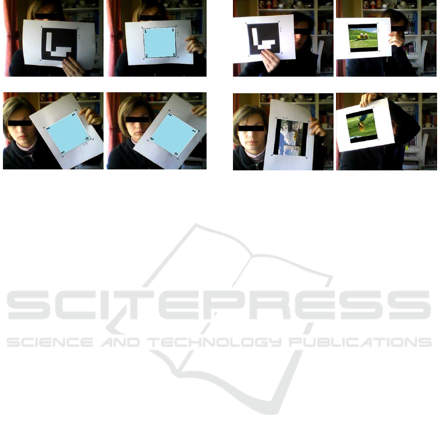
(a) (b)
(c) (d)
Figure 3: AR Applications - Images: (a) ArUco Marker;
(b)(c) and (d) the projection of a template image with the
same size of the marker and in different rotations.
of the related image plane. More specifically, we have
adopted this new matrix as well as the parameters of
calibration (cameraMatrix) and the coefficients of dis-
tortion (distCoeffs) to redefine the coordinates of the
four corners of the textured loaded image for map-
ping them on the coordinates of the four corners of the
marker. Instead of using the parameters of calibration
and coefficientsof distortion computed during the cal-
ibration phase, a set of default values can be adopted
which, however, decrease the performance of the sys-
tem in term of quality. As previously mentioned, the
merging of the textured images is performed by using
the GLFW library which also provides advanced anti-
aliasing functionalities to reduce the lack of quality
due to the continuous variation of the perspectives.
4.4.2 AR Applications - Video
This type of applications can be considered an exten-
sion of the previous ones. In Figure 4 an example is
reported. Note that, this time, each template frame
is overlapped on the marker with respect its size and
orientation. In particular, in Figure 4a, Figure 4b, and
Figure 4c three different frames at three different time
instants are shown. For each frame a process identi-
cal to that observed for a single image is applied. Al-
though the calculations of the geometric transforma-
tion and texturing are not so heavy from a computa-
tional point of view, at this stage assumes a huge im-
portance the setting of the acquired frames depending
on the capacity of the specific device. Also this as-
pect could be automatically guided by an application
able to check the hardware of the device, but it is not
argument of the proposed work.
(a) (b)
(c) (d)
Figure 4: AR Applications - Video: (a) ArUco Marker;
(b)(c) and (d) the projection of a template video with the
same size of the marker and in different rotations.
4.5 Hardware Setting
The whole experimental session was performed by
using two hardware settings: a primary setting (desk-
top) and a secondary setting (mobile). The first one,
a Windows 8.1 64-bit system (Intel Core i7-4860HQ,
2.4/3.6GHz, cache 6MB, RAM 16GB (DDR3L), HD
1TB (7200 rpm), NVIDIA GeForce GTX 980M
(8GB), HD Camera integrated), was adopted to test
each and every aspect of both the framework and AR
applications. The second one, an Android 5.1 (Octa-
Core 1.3/1.9Ghz, RAM 3GB, ROM 32GB, QHD
Camera integrated), was adopted to test some simple
AR applications. Despite the wide difference between
the two systems, in both cases the tests shown good
performance and recognition of the markers in real
time.
5 EXPERIMENTAL RESULTS
One of the main targets of the present paper is to show
a practical and effectiveframework to develop AR ap-
plications. For this reason, we have inserted an exten-
sive experimental session to describe the operation of
the generated applications in real contexts. Our intent
is to provide users with a general guide based on a
concrete experience.
5.1 Test Setting
We have chosen randomly 25 of the 1024 markers
available within the ArUco library. Each marker was
A Practical Framework for the Development of Augmented Reality Applications by using ArUco Markers
651

tested according to the following three main parame-
ters:
Marker Size: each marker was printed in three dif-
ferent sizes: 250 × 250, 150× 150 and 100× 100
pixels (pixel unit in millimetres: 0, 26×0, 26mm);
Recognition Distance: each marker was presented
to the camera with three different distances: 2, 1
and 0.5 meters. At each distance the marker was
rotated both with respect the centre of the camera
(360
◦
on the plan (x, y)) to check the recognition
with different verses and with respect the x and y
axes, respectively, to check the recognition with
different orientations;
Natural Light Intensity: each marker was tested
with different intensity of natural light, about
1000 (outdoor in a sunny morning), 850 (indoor
in a sunny morning) and 500 (indoor in a sunny
evening) lux (lx).
We performed about 225 videos in which a user
shown a marker to the camera following the previ-
ously introduced parameters. The success rate (P
Rec
)
of the recognition process was computed according to
the following formulation:
P
Rec
=
M
Dec
F
Num
× 100 (1)
where, M
Dec
represents the number of times in
which a marker was detected by the recognition en-
gine, and F
Num
represents the number of frames in
which a marker was completely (or partially) visible.
We adopted the hardware configuration introduced in
the previous section. Note that, we have reported only
the results of the recognition process since each appli-
cation worked always properly.
5.2 Outdoor - Natural Light (1000lx)
This subsection summarizes the results of the recogni-
tion process during a sunny morning in outdoor envi-
ronments. Markers sized 250× 250 show a high level
of recognition (about 90%) when they are about 1m
away from the camera. When the distance between
markers and camera is lower, also the success rate de-
creases due to the shadows created by users on the
surfaces where markers are applied. When the dis-
tance between markers and camera is higher, the suc-
cess rate is decreased due to reflection phenomena.
Markers sized 150× 150 show a situation similar to
the previous one where a general increase of the suc-
cess rate is reported. Finally, markers sized 100× 100
show a high level of recognition when they are about
0.50m away from the camera. When the distance be-
tween markers and camera is about 1m the recognition
rate decreases of about 30%. Over 2m it is no longer
possible to recognize the markers.
5.3 Indoor - Natural Light (850lx)
This subsection summarizes the results of the recog-
nition process during a sunny morning in indoor en-
vironments. Markers sized 250 × 250 show a high
level of recognition (about 90%) both when they are
about 0.5m away from the camera and when they are
about 1m away from the camera. A higher distance
between camera and markers causes a slight drop in
accuracy. These positive results are due to the uni-
form diffusion of the natural light within indoor en-
vironments which reduces shadows and reflections.
Markers sized 150 × 150 show a situation even bet-
ter than the previous one where the recognition rate
is increased when the distance between markers and
camera is both about 0.5m and about 1m. When this
distance is about 2m the recognition rate decreases of
about 15%. Finally, markers sized 100× 100 show a
high level of recognition only when they are about 1m
away from the camera. When the distance is lower,
the accuracy decreases too. Also in this case, over 2m
it is no longer possible to recognize the markers.
5.4 Indoor - Natural Light (500lx)
This subsection summarizes the results of the recog-
nition process during a sunny evening in indoor en-
vironments. Markers sized 250 × 250 show a low
level of recognition (about 60%) regardless of the dis-
tance between markers and camera. Markers sized
150×150show a situation similar to the previousone.
Finally, markers sized 100× 100 show a general low
level of recognition and, as in the other cases, over 2m
it is no longer possible to recognize the markers. Note
that, all the experimental sessions depend on the hard-
ware configuration reported in the last sub-paragraph
of the previous section. Despite this, the proportional-
ity among marker size, recognition distance and nat-
ural light intensity should remain unchanged. During
all the experimental sessions we handled as natural as
possible the acquisition device in order to simulate a
real interaction between it and fiducial markers.
6 CONCLUSIONS
The AR has become one of the emerging technolo-
gies both in academic research and in field of indus-
try. An ever-increasing number of applications are
designed to provide users with an enhanced interac-
tive multi-sensorial experience of the real-world that
ICPRAM 2016 - International Conference on Pattern Recognition Applications and Methods
652

surrounding them. In this context, our contribute has
been to provide a practical frameworkfor the develop-
ment of AR applications through which target objects
are enriched with multimedia information. The pro-
posed framework has been designed for general pur-
poses, for this reason it includes some special prop-
erties such as the adaptive placing of the multimedia
information on the fiducial markers, and the treatment
of different digital resources. Finally, we have per-
formed extensive experimental sessions to provided
users with a general guide based on a concrete expe-
rience. Currently, we are studying a novel approach
to define a new set of fiducial markers. We are also
studying an alternative approach to detect and rec-
ognize known markers in non-collaborative environ-
ments.
REFERENCES
Babinec, A., Juriica, L., Hubinsk, P., and Ducho, F. (2014).
Visual localization of mobile robot using artificial
markers. Procedia Engineering, 96(6):1–9.
Billinghurst, M., Clark, A., and Lee, G. (2015). A sur-
vey of augmented reality. Foundations and Trends in
Human-Computer Interaction, 8(2-3):73–272.
Chan, F., Lam, F., and Zhu, H. (1998). Adaptive thresh-
olding by variational method. IEEE Transactions on
Image Processing, 7(3):468–473.
Chen, W. (2014). Historical oslo on a handheld device a
mobile augmented reality application. Procedia Com-
puter Science, 35(3):979–985.
Choi, H., Cho, B., Masamune, K., Hashizume, M., and
Hong, J. (2015). An effective visualization technique
for depth perception in augmented reality-based surgi-
cal navigation. The International Journal of Medical
Robotics and Computer Assisted Surgery, pages 1–11.
Fahn, C.-S., Wu, M.-L., and Liu, W.-T. (2013). On the
use of augmented reality technology for creating in-
teractive computer games. In Virtual, Augmented
and Mixed Reality. Systems and Applications, volume
8022 of Lecture Notes in Computer Science, pages
353–362.
Fang, H., Ong, S., and Nee, A. (2014). A novel augmented
reality-based interface for robot path planning. Inter-
national Journal on Interactive Design and Manufac-
turing (IJIDeM), 8(1):33–42.
Ferrari, V., Viglialoro, R. M., Nicoli, P., Cutolo, F.,
Condino, S., Carbone, M., Siesto, M., and Ferrari,
M. (2015). Augmented reality visualization of de-
formable tubular structures for surgical simulation.
The International Journal of Medical Robotics and
Computer Assisted Surgery, pages 1–10.
Garrido-Jurado, S., Muoz-Salinas, R., Madrid-Cuevas, F.,
and Marn-Jimnez, M. (2014). Automatic generation
and detection of highly reliable fiducial markers under
occlusion. Pattern Recognition, 47(6):2280 – 2292.
Hagbi, N., Bergig, O., El-Sana, J., and Billinghurst, M.
(2011). Shape recognition and pose estimation for
mobile augmented reality. IEEE Transactions on Visu-
alization and Computer Graphics, 17(10):1369–1379.
Han, D.-I., Jung, T., and Gibson, A. (2013). Dublin ar:
Implementing augmented reality in tourism. In Infor-
mation and Communication Technologies in Tourism,
pages 511–523.
Jain, P. and Jawahar, C. (2006). Homography estimation
from planar contours. In Proceedings of the 3th In-
ternational Symposium of 3D Data Processing, Visu-
alization, and Transmission, pages 877–884.
Jung, K., Lee, S., Jeong, S., and Choi, B.-U. (2008). Vir-
tual tactical map with tangible augmented reality in-
terface. In Proceedings of the International Confer-
ence on Computer Science and Software Engineering,
volume 2, pages 1170–1173.
Jung, S. and Kim, S. (2012). Domain-specific marker
recognition method to improve marker efficiency and
reusability. In Computer Applications for Web, Hu-
man Computer Interaction, Signal and Image Pro-
cessing, and Pattern Recognition, volume 342 of
Communications in Computer and Information Sci-
ence, pages 126–132.
Kang, J.-S. and Lee, J.-J. (2015). Augmented reality and sit-
uation awareness applications for military computing.
Journal of Image and Graphics, 3(2):126–131.
Kourouthanassis, P., Boletsis, C., Bardaki, C., and
Chasanidou, D. (2015). Tourists responses to mobile
augmented reality travel guides: The role of emotions
on adoption behavior. Pervasive and Mobile Comput-
ing, 18(4):71–87.
Li, Y., Wang, Y.-T., and Liu, Y. (2007). Fiducial marker
based on projective invariant for augmented real-
ity. Journal of Computer Science and Technology,
22(6):890–897.
Liu, D. and Yu, J. (2009). Otsu method and k-means. In
Proceedings of the 9th International Conference on
Hybrid Intelligent Systems, volume 1, pages 344–349.
Pendit, U. C., Zaibon, S. B., and Bakar, J. A.A. (2014). Mo-
bile augmented reality for enjoyable informal learning
in cultural heritage site. International Journal of Com-
puter Applications, 92(14):19–26.
Pestana, J., Sanchez-Lopez, J., de la Puente, P., Carrio, A.,
and Campoy, P. (2014). A vision-based quadrotor
swarm for the participation in the 2013 international
micro air vehicle competition. In Proceedings of the
International Conference on Unmanned Aircraft Sys-
tems (ICUAS), pages 617–622.
Pettersen, T., Pretlove, J., Skourup, C., Engedal, T., and
Lokstad, T. (2003). Augmented reality for program-
ming industrial robots. In Proceedings of the 2th
IEEE and ACM International Symposium on Mixed
and Augmented Reality, pages 319–320.
Sanchez-Lopez, J., Pestana, J., de la Puente, P., Carrio, A.,
and Campoy, P. (2014). Visual quadrotor swarm for
the imav 2013 indoor competition. In ROBOT2013:
First Iberian Robotics Conference, volume 253 of Ad-
vances in Intelligent Systems and Computing, pages
55–63.
Speers, A., Topol, A., Zacher, J., Codd-Downey, R., Verz-
ijlenberg, B., and Jenkin, M. (2011). Monitoring un-
derwater sensors with an amphibious robot. In Pro-
A Practical Framework for the Development of Augmented Reality Applications by using ArUco Markers
653

ceedings of the Canadian Conference on Computer
and Robot Vision (CRV), pages 153–159.
Van-Krevelen, D. and Poelman, R. (2010). A survey of
augmented reality technologies, applications and lim-
itations. The International Journal of Virtual Reality,
9(2):1–20.
Zhang, Z. (2000). A flexible new technique for camera cal-
ibration. IEEE Transaction on Pattern Analysis and
Machine Intelligence, 22(11):1330–1334.
ICPRAM 2016 - International Conference on Pattern Recognition Applications and Methods
654
