
Design, Implementation and Testing of a Real Time System
to Unambiguously Assign Detected Vehicles from
Car-to-Car Communication and on-Board Camera
Simone Fontanesi
1,2
, Luca Fanucci
1
and Frank Hofmann
2
1
Information Engineering Department, University of Pisa, Via G. Caruso, Pisa, Italy
2
Robert Bosch GmbH, Corporate Research, Robert-Bosch-Strasse 200, Hildesheim, Germany
Keywords:
Car-to-Car Communication, on-Board Sensors, Camera, Sensor Fusion, ADAS, Real Time.
Abstract:
on-Board surround sensors, such as cameras and radars, are used in Advanced Driving Assistance Systems
applications to improve the driver safety and comfort. In the meantime, Car-to-Car Communication systems
are in the deployment phase and have been tested in huge test fields. In order to compensate the weaknesses and
benefit from the strengths of both systems, their information can be fused. In this context, one major challenge
is the unambiguous assignment of detected vehicles from different sensors, which is still an open research
topic and the major target of this work. An innovative algorithm was first tested in Matlab using recorded data
and then implemented on real hardware. The results obtained are promising and, from a spatial point of view,
they show already a successful matching of vehicles. Compared with the solutions proposed in literature, the
developed demonstrator is innovative, and represents the first step towards a real world application running
in real time inside cars. Overall, this work is a useful contribution to active safety and autonomous driving
applications based on sensor fusion and a good reference for further research on the topic.
1 INTRODUCTION
Advanced Driver Assistance Systems (ADAS) used to
improve traffic safety and driving comfort currently
rely on on-board surround sensors such as cameras
and radars. These sensors provide reliable relative po-
sitions between the own vehicle and detected objects,
but have a limited field of view and can suffer in situ-
ation with occlusion.
In parallel, Car-to-Car (C2C) and Car-to-
Infrastructure (C2I) Communication systems
(Baldessari et al., 2007; Fuchs et al., 2012) based on
ad hoc networking are in transition to deployment and
have already been tested in huge field tests (SimTD,
2008; Grace et al., 2012). These communication
systems deliver information about the position and
the movement state of cars and can extend the driver
horizon with a higher range and non-line of sight
capabilities. However, GPS position precision and
communication channel congestion problems could
affect the quality of the received data.
Therefore, the next logical step is the fusion of in-
formation from on-board surround sensors and C2C
Communication, to benefit from the strengths of both
systems and to compensate their weaknesses. In this
regard, one major challenge is the unambiguous as-
signment of detected vehicles from different sources.
2 STATE OF THE ART
While many publications have addressed the problem
of sensor fusion between on-board sensors, not much
work has been done using also C2C Communication
data. The most significant publications related to the
topic of this paper are probably (Thomaidis et al.,
2011; Obst et al., 2014). Indeed, (Thomaidis et al.,
2011) addresses the problem of associating and fus-
ing tracks coming from on-board long range radar
with received vehicle positions from the vehicular
network. In this paper the Unscented Kalman filter
is used together with the constant turn rate and ac-
celeration model to obtain vehicle tracks from Coop-
erative Awareness Messages (CAMs), the messages
sent on a regular basis from the vehicles contain-
ing data regarding their position and their current dy-
namic state. The results of this work show that us-
ing the ITS G5 ad hoc network data the vehicle in
front is tracked for 67% time frames more in com-
parison to radar sensor only, as the route consists in
20
Fontanesi, S., Fanucci, L. and Hofmann, F.
Design, Implementation and Testing of a Real Time System to Unambiguously Assign Detected Vehicles from Car-to-Car Communication and on-Board Camera.
In Proceedings of the International Conference on Vehicle Technology and Intelligent Transport Systems (VEHITS 2016), pages 20-30
ISBN: 978-989-758-185-4
Copyright
c
2016 by SCITEPRESS – Science and Technology Publications, Lda. All rights reserved
many curves and the target is often outside the radar
field of view (FOV). Moreover, the authors affirm that
only 1% of all track associations are wrong. Instead,
in (Obst et al., 2014) C2C Communication and cam-
era data are fused to check the correctness of CAM
content. The cross-correlation between the data from
CAMs and the MobilEye camera (Mobileye, 2015) is
used to check the plausibility of received CAMs and
to compute the existence probability of sending ve-
hicles. In this way, the authors think that problems
such as the malicious injection of a ghost-vehicle in
the ITS G5 network could be avoided, providing a
higher level of security to the users. The Kalman fil-
ter is used and the vehicle dynamics is described with
constant velocity model. The fusion happens at track-
level, hence there is a first measurement-to-track as-
sociation step. Overall the results seem promising,
but only one particular scenario is shown. A differ-
ent approach is used in (Matthias R
¨
ockl and Thomas
Strang and Matthias Kranz, 2008; Matthias R
¨
ockl and
Jan Gacnik and Jan Schomerus, 2008), which consid-
ers C2C communications as a complementing sensor
for future driver assistance systems. In these papers
a particle filter is used to generate target tracks, so
that both the system and the noise can be described
with non-linear and non-Gaussian models. The re-
sults show good accuracy in the mean of the distri-
bution, especially when the target is close and in the
ego vehicle FOV. However, no real data are used to
evaluate the algorithm performances. Indeed, all the
evaluations happen within a simulation environment
called CODAR (Matthias R
¨
ockl and Thomas Strang
and Matthias Kranz, 2008).
In conclusion, the problem of data fusion be-
tween C2C Communication and on-board sensors still
presents open challenges and room for improvement.
In particular, no comprehensive solutions for unam-
biguous car detection and matching between detected
vehicles from different systems have been presented
yet. Of course, this makes the topic interesting and
innovative, both from a research and practical appli-
cation point of view.
3 METHODOLOGY
This section deals with the most important aspects of
the study and describes the major parts of the research
done, both from a theoretical and practical point of
view. In particular, Section 3.1 presents the over-
all experimental setup and provides information re-
garding the hardware used to collect significant data.
Then, Section 3.2 describes the challenges faced dur-
ing the algorithm design, and the respective adopted
solutions. Finally, Section 3.3 gives an overview of
the algorithm main steps, while the actual real time
implementation is described in Section 3.4.
3.1 Experimental Setup
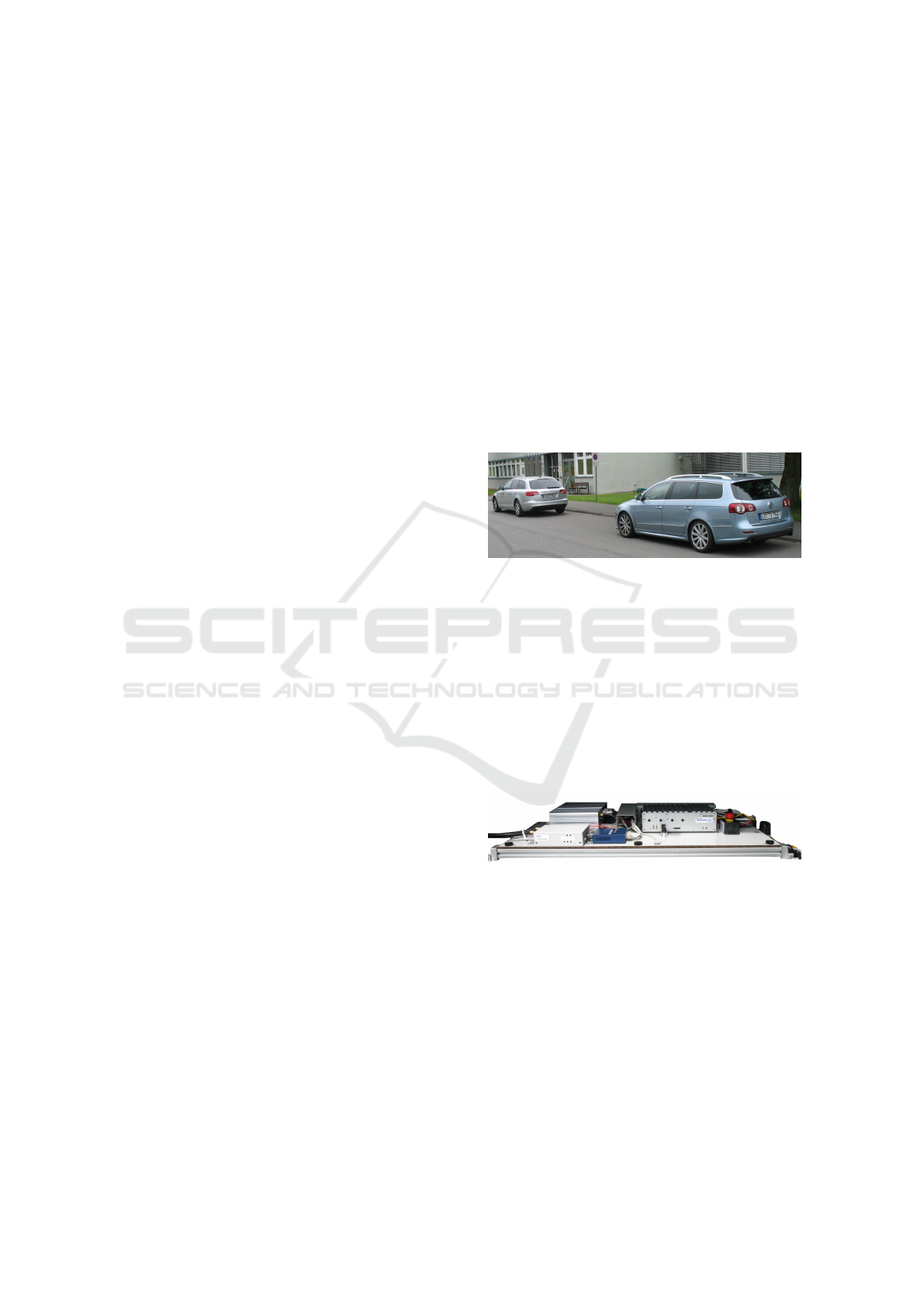
All the data used to test the algorithm have been
recorded as part of this work using a Volkswagen
Passat B6 wagon and an Audi A6 Avant, both in-
side and outside the company premises. The Passat
is equipped with both video and C2C Communication
systems, while the Audi includes only the latter. For
this reason in all the recordings the Audi is driving in
front of the Passat, allowing the camera to detect the
same vehicle that is sending CAMs. Figure 1 shows
the described scenario.
Figure 1: Experimental setup.
The hardware used for the C2C Communication
system corresponds to the ETSI ITS G5 standards
and Figure 2 shows a prototype implementation. As
for the video system, the camera used in this work
is the second generation multi purpose camera MPC2
premium (Robert Bosch GmbH, 2015) developed by
Bosch, which is able to recognize pedestrians, vehi-
cles, road lanes and traffic signs. The detection range
depends on the object size, and for vehicles it extends
to more than 120 m (Robert Bosch GmbH, 2015).
Figure 2: C2C Communication hardware.
3.2 Design Challenges
3.2.1 Sensor Fusion Mechanism
In multi-sensor problems involving target tracking
two approaches are possible:
• Measurement-level fusion:raw data coming from
sensors are preprocessed and directly combined to
obtain the detected object tracks.
• Track-level fusion: for each sensor raw data are
preprocessed and further elaborated to obtain tar-
Design, Implementation and Testing of a Real Time System to Unambiguously Assign Detected Vehicles from Car-to-Car Communication
and on-Board Camera
21

get tracks. Then, considering the tracks belong-
ing to the same target a unified information is pro-
duced.
The second approach has been used in this work
because it allows to structure the problem in a mod-
ular way and has less strict requirements on temporal
alignment and statistical knowledge of sensor behav-
ior.
3.2.2 Geographic Coordinate Conversion
The spatial alignment between data coming from var-
ious sources is a necessary requirement in sensor fu-
sion applications related to target detection and track-
ing. In our case the C2C Communication system pro-
vides the car positions in absolute coordinates, while
the distances from the camera are referenced to the
ego vehicle rear axle. Moreover, the C2C coordinates
are expressed using the WGS84 format, which is not
suitable for tracking applications and for this reason a
first conversion into the Universal Transverse Merca-
tor (UTM) format is needed. To convert from WGS84
to UTM, the formulas suggested in (Snyder, 1987)
have been used.
As for the video system, the relative distance com-
ponents from the video system are first projected onto
the x and y UTM axes using a rotation matrix, then
added to the ego vehicle position.
3.2.3 Time Synchronization
Concerning the C2C Communication system, all the
CAMs include the time instant in which the mes-
sage was generated, expressed in milliseconds and
referenced to 2004-01-01T00:00:00.000Z (European
Telecommunications Standards Institute, 2014). In
particular, all ITS G5 network vehicles (including the
ego vehicle) use the same time scale, hence it is quite
easy to synchronize and align the data from different
cars.
In order to align the camera data with the infor-
mation from the CAMs and the ego vehicle, some
modifications have been made to the existing system
configuration: the application unit of the C2C Com-
munication system is connected directly to the Pri-
vate CAN bus of the Passat to access the camera data
and to add a timestamp to them using the same refer-
ence. Even with this configuration some uncertainty
is present, indeed data are timestamped when they are
received on the CAN bus, and not when the frame is
captured from the camera. In order to minimize the
average error, a fixed offset value defined by a Matlab
simulation is added to all the camera time instants.
This does not completely remove the timing errors
because both the frame processing time and the CAN
sending time are not constant, but it is enough to pro-
ceed further with the study.
3.2.4 Target Track Generation
Tracking is the processing of measurements obtained
from a target in order to maintain an estimate of its
current state (Bar-Shalom and Li, 1995). Since the
state observations are affected by noise and could be
potentially wrong, usually a probabilistic algorithm
involving an a priori model is used. Our implementa-
tion uses the Kalman filter (Bar-Shalom and Li, 1993)
to update the vehicle tracks, both for C2C and video
systems. (Robin Schubert and Christian Adam and
Marcus Obst and Norman Mattern and Veit Leonhardt
and Gerd Wanielik, 2011) concludes that in applica-
tions where only the position is needed, linear mod-
els perform quite well and the complications intro-
duced by non-linear models are unjustified. For this
reason, linear models and classic Kalman filter have
been used in the project.
Concerning the C2C data, one vendor might sim-
ply connect a low-cost GPS receiver, while another
one implements a sophisticated vehicle positioning
algorithm (Obst et al., 2014). Nowadays some of the
GPS errors can be corrected with mathematical mod-
els or advanced GPS techniques. However, measure-
ments could still be inaccurate and imprecise. More-
over, the GPS receiver position is updated at low fre-
quencies (approximately 1 Hz), which are not com-
patible with the requirements of automotive ADAS
applications. Using the Kalman filter, it is possible
to update the vehicle position more often, integrat-
ing GPS data with dead reckoning techniques. In the
Kalman filter implementation the Constant Acceler-
ation (CA) model has been used. In the reality, the
acceleration is not constant and the vehicle dynamics
is different from the CA model. In (Bar-Shalom and
Li, 1993) two possibilities for modeling the accelera-
tion error are presented. The continuous-time model
has been used because, since the target moves contin-
uously over time, it is more accurate than its discrete-
time counterpart (X. Rong Li and Vesselin P. Jilkov,
2004). In figures 3 and 4 the improvements deriving
from the Kalman filter are shown. Figure 3 presents a
comparison between the GPS coordinates of the send-
ing vehicle before and after the Kalman filtering. In
particular, it is possible to appreciate that the position
is updated more frequently after the filtering. Figure
4 instead shows how the filter behaves when an incor-
rect GPS position is received.
Also for the camera data it is convenient to use
the Kalman filter to generate the target tracks. In-
deed, it allows to have a smoother trajectory and to
VEHITS 2016 - International Conference on Vehicle Technology and Intelligent Transport Systems
22
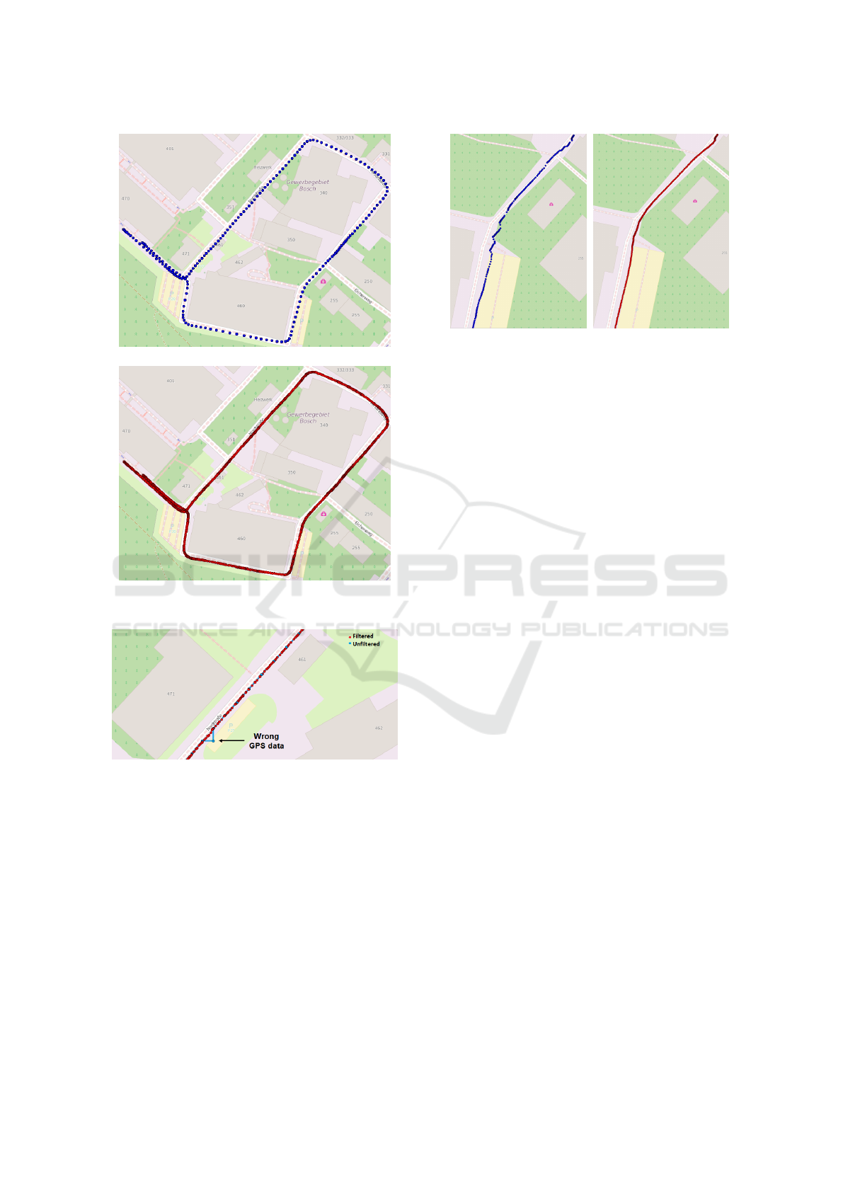
(a) Unfiltered.
(b) Filtered.
Figure 3: Audi track from C2C Communication system.
Figure 4: Kalman filter with wrong measurements.
give less importance to outliers or wrong data. Differ-
ently from CAM data, target vehicle speed and accel-
eration are not available from the video system. For
this reason, to describe the vehicle dynamics the Con-
stant Velocity (CV) model has been preferred over the
CA model. Figure 5 shows a comparison of the target
positions before and after Kalman filtering.
3.3 Algorithm Overview
The output of the algorithm is the association of ve-
hicles from different sources. The inputs consist in
the information included inside CAMs and in the data
from the camera. In addition, ego vehicle information
(a) Unfiltered. (b) Filtered.
Figure 5: Audi track from video system.
such as GPS position, speed and acceleration is used.
The C2C Communication system algorithm uses
the received CAMs to generate and maintain the send-
ing vehicle tracks in UTM coordinates. First of all,
from the vehicle type field it is possible to know if the
message comes from an entity of interest. In particu-
lar, if the message comes from a different source it is
ignored, otherwise it is considered for the following
steps of the algorithm. Then, the vehicle ID field is
used to determine whether the message has been sent
from a new vehicle or if a track already exists for it.
As in (Thomaidis et al., 2011), the vehicle pseudonym
has been considered constant for simplicity. At this
point two options are possible: if the sending vehicle
is a new vehicle its track is initialized, otherwise its
track is updated with the new measurement. In par-
ticular, the latitude and the longitude are converted
into UTM coordinates. Then, the speed and the ac-
celeration components in the UTM reference system
are obtained from the respective absolute values and
the vehicle heading. Indeed, using the notation pre-
sented in figures 6 and 7, the following equations can
be written:
v
x
= v sin(θ
UT M
)
v
y
= v cos(θ
UT M
)
(1)
a
x
= a
long
sin(θ
UT M
) − a
lat
cos(θ
UT M
)
a
y
= a
long
cos(θ
UT M
) + a
lat
sin(θ
UT M
)
(2)
With this information the Kalman filter prediction
and update steps are used to successfully update the
vehicle track. These are:
State Prediction
(
ˆ
x
k+1|k
= A
k
ˆ
x
k|k
P
k+1|k
= A
k
P
k|k
A
T
k
+ Q
k
(3)
Design, Implementation and Testing of a Real Time System to Unambiguously Assign Detected Vehicles from Car-to-Car Communication
and on-Board Camera
23
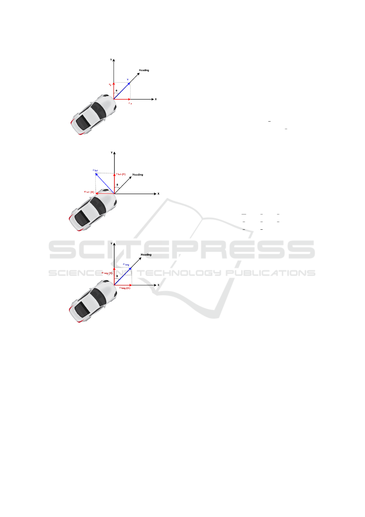
Figure 6: WGS84 to UTM conversion of vehicle speed.
(a) Lateral acceleration.
(b) Longitudinal acceleration.
Figure 7: WGS84 to UTM conversion of vehicle accelera-
tion.
State Update
(
ˆ
x
k+1|k+1
=
ˆ
x
k+1|k
+ K
k+1
y
k+1
− C
k+1
ˆ
x
k+1|k
P
k+1|k+1
= (I − K
k+1
C
k+1
)P
k+1|k
(4)
where:
• x ∈ ℜ
n
= state vector
• y ∈ ℜ
m
= observation vector
• A ∈ ℜ
n×n
= state transition matrix
• C ∈ ℜ
m×n
= observation matrix
• P = state estimate covariance matrix
• Q = state evolution noise covariance matrix
• R = measurement noise covariance matrix
• K
k+1
= P
k+1|k
C
T
k+1
C
k+1
P
k+1|k
C
T
k+1
+ R
k+1
−1
In particular, for the considerations made in Section
3.2.4, the matrices are:
A =
1 0 T
k
0
1
2
T
2
k
0
0 1 0 T
k
0
1
2
T
2
k
0 0 1 0 T
k
0
0 0 0 1 0 T
k
0 0 0 0 1 0
0 0 0 0 0 1
(5)
C =
1 0 0 0 0 0
0 1 0 0 0 0
0 0 1 0 0 0
0 0 0 1 0 0
0 0 0 0 1 0
0 0 0 0 0 1
(6)
Q = S
v
1
20
T
5
k
1
8
T
4
k
1
6
T
3
k
1
8
T
4
k
1
3
T
3
k
1
2
T
2
k
1
6
T
3
k
1
2
T
2
k
T
k
(7)
where S
v
is the power spectral density of the
continuous-time white noise in the state evolution
process and T
k
= t
k+1
−t
k
is the time interval between
the instants t
k+1
and t
k
.
The camera algorithm uses the information re-
garding the objects detected by the video system to
generate and maintain target tracks in UTM coordi-
nates. First of all, the vehicle type field determines if
the detected object should be considered or ignored.
If the detected object is a car, a truck or a motorcy-
cle, then the object ID is considered to distinguish
between new vehicles and vehicles that have already
been observed. In particular, a new track is gener-
ated only if the probability existence field of the new
observation is high enough. This information is pro-
vided together with each detection and gives a prob-
ability estimate of its correctness. Every time a track
is updated, it is necessary to convert the relative dis-
tance between the ego vehicle and the target into the
UTM absolute position. In particular, the ego vehicle
UTM coordinates are generated and filtered using the
same procedure used for CAMs and then interpolated
at the time instants in which the target was detected
from the camera. Using the notation of Figure 8, the
conversion is made applying the following equations:
x
UT M
= x
ego
+ ∆x
UT M
y
UT M
= y
ego
+ ∆y
UT M
(8)
where ∆x
UT M
and ∆y
UT M
are calculated as:
VEHITS 2016 - International Conference on Vehicle Technology and Intelligent Transport Systems
24

∆x
UT M
= ∆x sin (θ
UT M
) − ∆y cos(θ
UT M
)
∆y
UT M
= ∆x cos (θ
UT M
) + ∆y sin(θ
UT M
)
(9)
Once the target coordinates are available in the
UTM format, the Kalman filter algorithm prediction
and update steps are computed. In this case, the ma-
trices are:
A =
1 0 T
k
0
0 1 0 T
k
0 0 1 0
0 0 0 1
(10)
C =
1 0 0 0
0 1 0 0
(11)
Q = S
v
1
3
T
3
k
1
2
T
2
k
1
2
T
2
k
T
k
(12)
As shown is Section 3.2.4, the filtering enables to
smooth the trajectory of the detected vehicles and to
reduce the effect of outliers, improving the successive
fusion results.
Finally, it is possible to fuse the data and perform
the matching between the detected objects. Indeed,
every time a new frame is processed from the video
system, the algorithm checks the similarity between
each camera track and the ones currently available
from the CAMs. In particular, the Euclidean distance
is used to calculate the difference in meters between
corresponding positions. Two different methods have
been utilized to compare the data in simulation:
• Considering only space.
• Considering both space and time.
The first method does not take into account the
time instant in which a measurement was taken and
for each position sample of the camera tracks the dis-
tance from the closest point in C2C Communication
tracks is calculated. In practice this gives an estimate
of how similar the tracks are, but only from a spatial
point of view. On the other hand, the second method
considers also the time and compares points taken at
the same instant. In this case two tracks are similar
only if both spatial and temporal alignment are cor-
rect and accurate. Depending on the application, dif-
ferent methods to compute the track similarity could
be adopted. In this work three strategies have been
used for evaluating the results:
• Considering whole tracks.
• Considering only the last sample of each track.
• Considering the samples included inside a moving
time window.
When more than one sample is considered the
mean value of the distances is computed to have an
overall estimate of how similar the two tracks are. In
order to have a more reliable measurement, outliers
are removed before calculating the mean value.
3.4 Algorithm Implementation
The actual algorithm implementation consists of Java
functions to collect and process in real time the data
from the different systems. Indeed, the applica-
tion unit of the C2C Communication system is pro-
grammed in Java using an OSGi framework, a set
of specifications that enables a development model
where applications are dynamically composed of
many different reusable components (OSGi Alliance,
2015). The main advantage of using OSGi is the
possibility to hide the implementation details of each
component, and make them communicate through
services using a publish-subscribe interface. The
event publish-subscribe mechanism has been largely
used in the implementation, to keep the data collec-
tion independent from the processing phase. Overall
four bundles have been developed to collect, log and
process the data coming from the different system. To
access the data on the CAN bus a dedicated library in
C has been developed and then imported in the Java
code using the Java Native Interface (JNI).
As shown in Figure 13, the user interface (UI) dis-
played on an in-car monitor, consists mainly of two
graphs, the bigger one displaying the vehicle tracks
in UTM coordinates and the other showing the differ-
ence in meters between the Audi position from C2C
Communication and video systems over time. On the
right side of the main application window, there are
some buttons and text fields that allow the user to vi-
sualize the data and to control the behaviour of the
UI.
4 RESULTS
This section shows the results obtained using the al-
gorithm developed within this research work. Two
driving scenarios have been considered, analysing the
data collected both inside and outside the company
location. Inside the company grounds both cars drive
slowly and the Audi often disappears from the FOV
of the camera due to the numerous curves, while out-
side, in a normal traffic environment, the speed is
higher and the target vehicle is continuously detected
because of the topology of the street.
Design, Implementation and Testing of a Real Time System to Unambiguously Assign Detected Vehicles from Car-to-Car Communication
and on-Board Camera
25
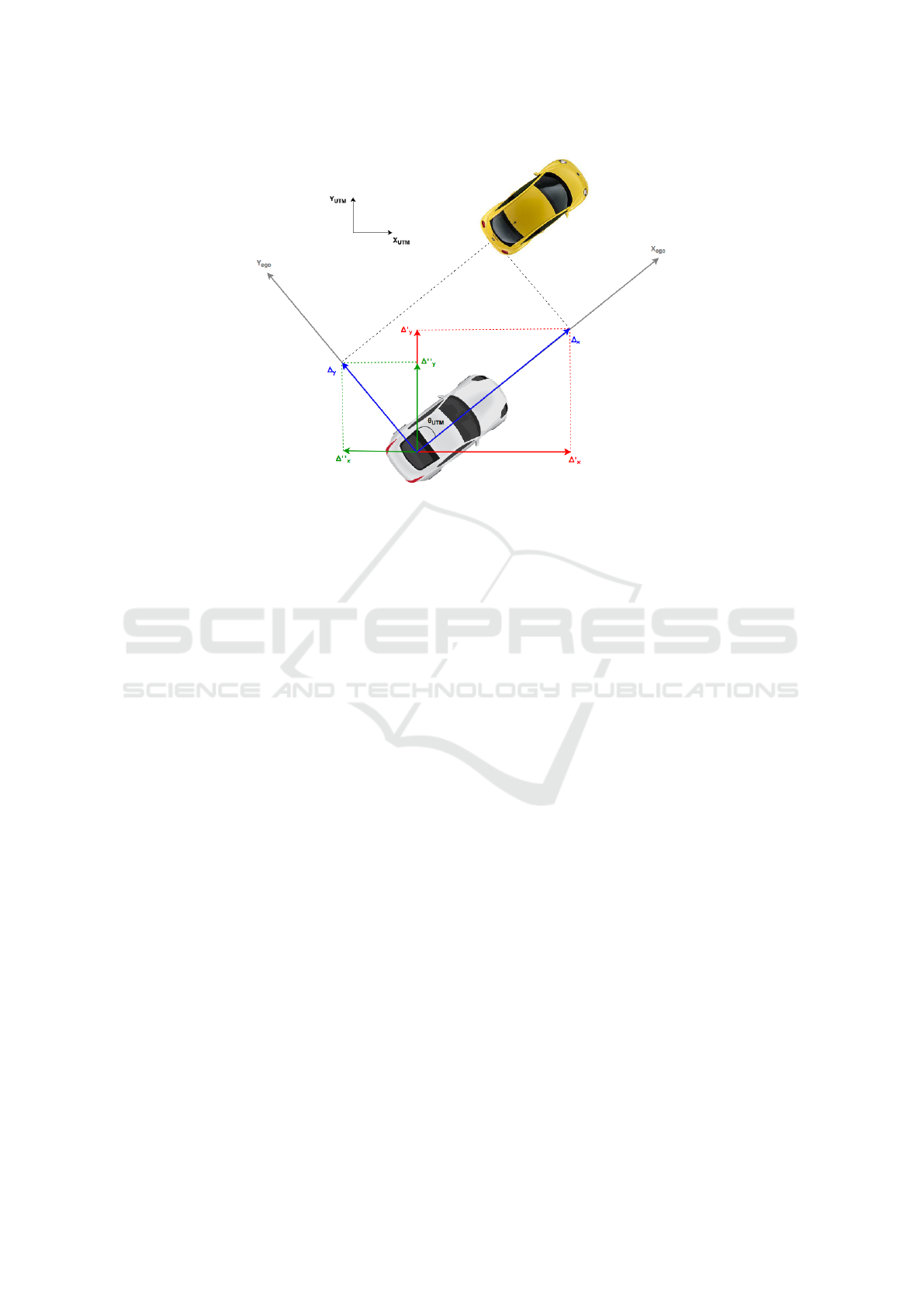
Figure 8: Coordinate conversion from relative to absolute.
4.1 Simulation Results
Before evaluating the results numerically, it is use-
ful to visualize the situation to understand intuitively
what happens. Figure 9 shows a comparison between
the Audi track generated from the CAMs and the ones
from the video system. In particular, the track ob-
tained from the C2C Communication system is drawn
in red, while the tracks from the camera have a dif-
ferent color every time a new ID is assigned to the
car. This happens, for example, when the Audi disap-
pears from the FOV of the camera, or when the cam-
era detects other vehicles in a new frame and assigns
them the ID previously belonging to the Audi. The
tracks almost always overlap and overall the match-
ing is good. Only the first camera track (on the left,
starting at about X=150m,Y=200m) is wrong, but this
does not depend on the algorithm as it is due to an
intrinsic error in the GPS at the time in which the
recording was taken. Besides this, some minor prob-
lems are present after the curves, when the car is de-
tected again from the camera but the ego vehicle is
still curving. This leads to a drift in the target vehicle
track, which differs from the one obtained from the
CAMs.
As with Figure 9, Figure 10 compares the tracks
obtained from the two systems. This time the UTM
coordinates are projected back into the WGS84 for-
mat using the formulas in (Beauducel, 2014), in order
to display the car position on an OpenStreetMap map
(OpenStreetMap, 2015).
Using the same data of the previous figures, Ta-
ble 1 shows for each camera track the ID assigned to
the vehicles, the time interval in which the object was
tracked from the video system and the mean distance
from the CAM track. In particular, the mean distance
is calculated taking into account all the points of a
track and using two different methods, which consider
only the space and both the space and the time. In the
first case for each element of a camera track the dis-
tance is calculated from the closest point in the CAM
track, while in the latter points are compared consid-
ering the time in which the samples were taken.
When only the space is considered, the results
show that on average the mean difference between
camera and CAM tracks is small and the matching
is almost perfect. Indeed, besides the first track that is
affected by the GPS offset problem, in all the other
cases the error is smaller than 2m and most of the
time stays below 1 m. This shows that the spatial
alignment between the two systems is good, and that
from this point of view the sensor fusion is success-
ful. However, when with the same data also the time
is taken into account, the mean error drastically in-
creases, being always higher than 3m and often more
than 9 m. Three factors can be considered as the
main reason for this behaviour. First of all, the time
alignment between the data from the C2C Commu-
nications system and the camera is not perfect due
to the reasons explained in Section 3.2.3. Moreover,
the GPS receivers of both cars update the position
just every second. Considering the information avail-
able from the ego vehicle CAN bus and CAMs, the
Kalman filter is used to update the position more fre-
quently. However, vehicles behave differently from
VEHITS 2016 - International Conference on Vehicle Technology and Intelligent Transport Systems
26
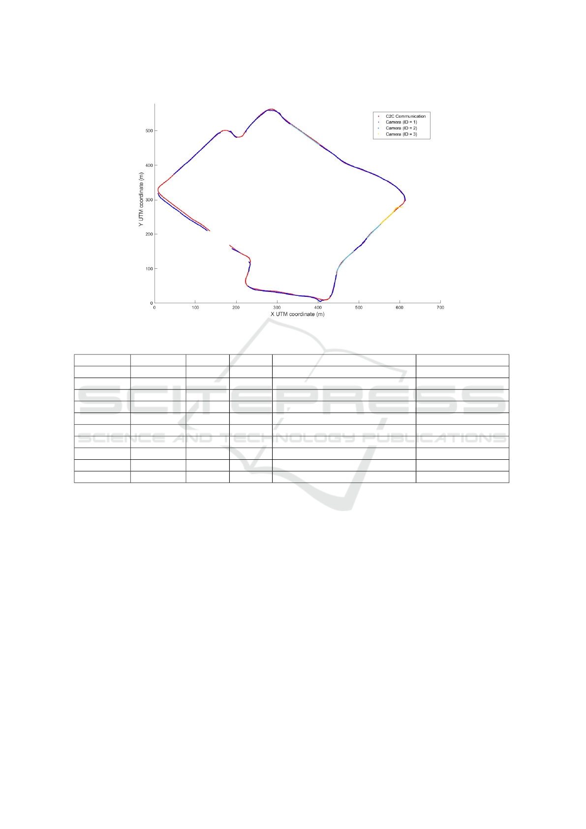
Figure 9: Audi tracks from C2C Communication and video systems.
Table 1: Sensor fusion algorithm results considering the whole tracks (inside company location).
CAM ID Camera ID Start (s) Stop (s) Mean difference (only space) (m) Mean difference (m)
444763658 1 0 25.25 5.19 11.46
444763658 1 36.23 91.80 0.89 11.90
444763658 2 91.97 102.95 1.60 11.72
444763658 1 103.17 144.11 0.79 9.44
444763658 3 147.80 158.68 0.61 7.80
444763658 2 158.88 169.90 0.65 5.18
444763658 1 170.07 181.05 0.63 3.36
444763658 2 181.17 192.19 0.78 7.95
444763658 1 192.36 229.60 1.32 9.68
444763658 1 237.02 251.43 0.84 9.34
the model, thus the predicted position can be dif-
ferent from the real one. In particular, the vehicle
could be projected in front or behind its real position,
which unfortunately is unknown. Since the problem
is present in both vehicles, the error introduced can
become relevant. Finally, the longitudinal distance
accuracy of monocular cameras is typically worse
than the lateral distance accuracy (William J. Flem-
ing, 2008), and in particular the relative error can in-
crease linearly with the distance from the target (Stein
et al., 2003). When only the space is considered the
longitudinal offset introduced does not affect the re-
sults, but when also the time is taken into account this
error can become important.
Considering all the points of each track is useful
to have a general idea regarding how good the al-
gorithm performs. However, in real applications it
would make more sense to consider just the new data,
or the most recent data within a certain time interval
in case the history of the system is of interest. In this
way, the periods of time in which the tracks are simi-
lar are not influenced by the periods in which they are
different, as for example immediately after a curve.
Figures 11 and 12 show the distances between one
camera track and the corresponding CAM track over
time. In particular, in Figure 11 just the new sam-
ples are considered to compute the difference, while
in Figure 12 the difference is calculated using a mov-
ing average over the last two seconds. In the reality,
this value would vary depending on the application,
since many factors such as the speed of the vehicle
should be taken into account. In our case the value
has been chosen to have an adequate number of sam-
ples to average and because the covered space was
big enough (a car moving at 50 kmh
−1
makes about
30 m in 2 s). The red line in the graphs represents
Design, Implementation and Testing of a Real Time System to Unambiguously Assign Detected Vehicles from Car-to-Car Communication
and on-Board Camera
27
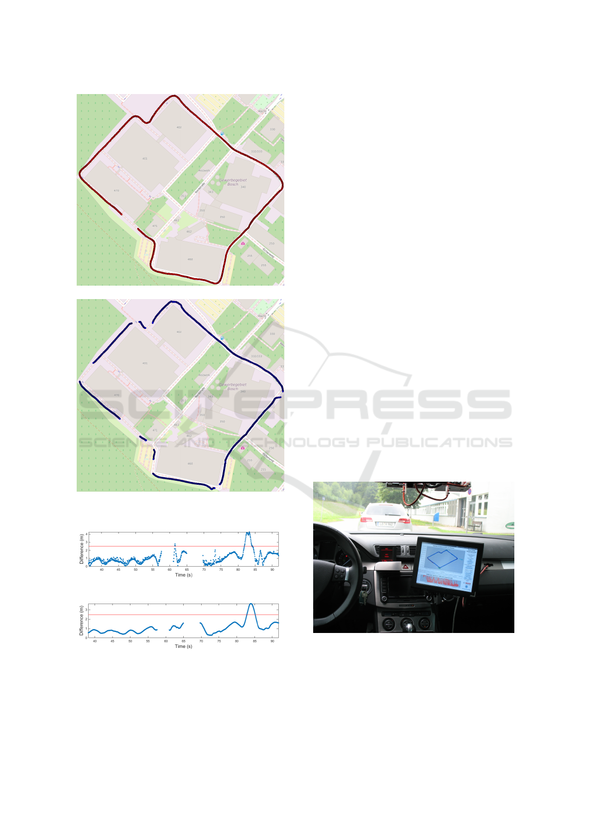
(a) C2C Communication.
(b) Camera.
Figure 10: Audi track on a map.
Figure 11: Difference between Audi tracks over time.
Figure 12: Difference between Audi tracks over time using
moving average.
a hypothetical threshold value that decides when the
matching between the tracks happens. In other words,
values below the red line represent positive matching.
The threshold has been adjusted to 2.5 m, considering
the average car and street dimensions.
The same Matlab simulations have been per-
formed also on the data recorded outside the company
location. In this scenario the streets are mostly long
and straight, and it is possible to drive faster than in-
side. As with the results presented in Table 1, the dif-
ference is small if only the space is considered. On the
other hand, when also the time is taken into account,
the same problems analysed for the first scenario arise
and the results get worse of about a factor of ten.
4.2 Implementation Results
The results obtained with the real time implementa-
tion of the algorithm are perfectly aligned with the
ones from the evaluation of the recorded data in Mat-
lab. Concerning the software performance and the re-
source utilization, the real time demonstrator is able
to run smoothly on the Java Virtual Machine (JVM)
installed on the C2C Communication hardware and
most of the resource usage derives from the data visu-
alization.
Overall, the results obtained from the real time im-
plementation of the algorithm can be considered pos-
itive and promising. Indeed, the demonstrator devel-
oped in this work represents the first step towards a
real world application running in real time inside ve-
hicles. This is something new and innovative com-
pared to the state of the art works, which consist
mainly in simulations based on fictitious or previously
recorded data and do not allow the online visualiza-
tion of the results.
Figure 13: Real time demonstrator.
4.3 Future Work
To obtain a better time alignment of the data, the
video messages sent on the CAN bus should be times-
tamped directly from the camera using the ITS G5
VEHITS 2016 - International Conference on Vehicle Technology and Intelligent Transport Systems
28

network time reference. This could be easily done
changing the current camera firmware or using a de-
vice that provides the functionality by default.
In order to obtain better track matching results
when also the time is considered, the procedure used
to update the position over time should be improved
as well. First of all, it would be helpful to repeat the
tests with the same algorithm but using a better GPS
receiver to obtain more frequent and accurate posi-
tion updates. Secondly, more sophisticated dynam-
ics models could be used to predict the vehicle po-
sition. Other sensors, such as radar, lidar or stereo
camera could replace the monocular camera or could
be added to the current system. In particular, using
these sensors it would be possible to improve the ac-
curacy in the distance measurement and to achieve
better results in the matching when also the time is
taken into account. This would not require too much
effort, given the modular approach used to design the
algorithm.
Finally, another direction in which the future work
should focus is the analysis of more scenarios. First
of all, it would be extremely useful to use at least
three vehicles sending and receiving CAMs, in or-
der to have not only multiple targets from the cam-
era, but also from the C2C Communication system.
Moreover, different driving scenarios should be con-
sidered, for example with the target car arriving from
an intersection, or during overtaking.
5 CONCLUSIONS
In this work a sensor fusion algorithm to unambigu-
ously assign detected vehicles from C2C Communi-
cation and on-board sensors has been designed and
implemented in real-time. All the main challenges
faced during the design phase, i.e., the data collection
procedure, the sensor fusion mechanism to be used,
the spatial and the temporal alignment of data from
the two systems and the track generation process,
have been described and a solution to each problem
has been proposed. Then, the sensor fusion algorithm
has been developed and tested in Matlab using differ-
ent metrics to evaluate the results and to understand
the most critical parts that should be improved in the
future work. Both simulated and recorded data from
real driving scenarios have been used in this phase
and, for this purpose, specific tools for data acquisi-
tion and storage have been deployed as well. Finally,
the algorithm has been implemented inside an in-car
system to demonstrate its capabilities in real time and
to offer a convenient debugging environment for fur-
ther research on the topic.
The overall results obtained using the developed
algorithm are promising. In particular, the Matlab
simulations show excellent results from a spatial point
of view, with a successful and unambiguous detec-
tion and matching of target vehicles. Further research
should be done to obtain likewise satisfying results
when also the time is considered in the calculation of
the difference between tracks. In this regard, concrete
ideas and possible solutions for further research have
been given. Concerning the results obtained with the
real time implementation of the algorithm, they are
perfectly aligned with the ones from the Matlab sim-
ulations and can be considered positive and encour-
aging as well. Compared with the solutions proposed
so far in literature, the demonstrator that has been de-
veloped in this work is new and innovative, and rep-
resents the first step towards a real world application
running in real time inside vehicles.
In order to obtain a reliable product that can be
used in applications, further work on this topic should
be done. Nevertheless, this work represents a good
basis for the future research and an important con-
tribution to the field of ADAS applications based on
sensor fusion.
REFERENCES
Baldessari, R., B
¨
odekker, B., Brakemeier, A., Deegener,
M., Festag, A., Franz, W., Hiller, A., Kellum, C.,
Kosch, T., Kovacs, A., Lenardi, M., L
¨
ubke, A., Menig,
C., Peichl, T., Roeckl, M., Seeberger, D., Strassberger,
M., Stratil, H., V
¨
ogel, H.-J., and Zhang, B. W. W.
(2007). CAR 2 CAR Communication Consortium
Manifesto. Technical report, CAR 2 CAR Commu-
nication Consortium.
Bar-Shalom, Y. and Li, X.-R. (1993). Estimation and Track-
ing: Principles, Techniques, and Software. Artech
House.
Bar-Shalom, Y. and Li, X.-R. (1995). Multitarget-
Multisensor Tracking: Principles and Techniques.
YBS Publing, 1st edition.
Beauducel, F. (2014). ll2utm. http://www.mathworks.com/
matlabcentral/fileexchange/45699-ll2utm-and-utm2ll/
content/Codes/matlab/ll2utm.m. [Online; accessed
07-April-2015].
European Telecommunications Standards Institute (2014).
Etsi ts 102 894-2 v1.2.1: Intelligent Transport Sys-
tems (ITS); Users and applications requirements; Part
2: Applications and facilities layer common data dic-
tionary. Technical Specification.
Fuchs, H., Hofmann, F., L
¨
ohr, H., Schaaf, G., and Kleine-
Besten, T. (2012). Car-2-X. In Winner, H., Hakuli,
S., and Wolf, G., editors, Handbuch Fahrerassisten-
zsysteme: Grundlagen, Komponenten und Systeme f
¨
ur
aktive Sicherheit und Komfort.
Design, Implementation and Testing of a Real Time System to Unambiguously Assign Detected Vehicles from Car-to-Car Communication
and on-Board Camera
29

Grace, N., Oxley, C., Sloan, S., Tallon, A., andTammy
Black, P. T., Easton, A. V., program managers of
the ITS Joint Program Office and the Federal High-
way Administration, T., the Federal Motor Carrier Ad-
ministration, the Federal Transit Administration, the
National Highway Traffic Safety Administration, the
Research, and Administration, I. T. (2012). Trans-
forming Transportation through Connectivity: ITS
Strategic Research Plan, 2010 - 2014 (Progress Up-
date, 2012). Strategic Plan Report, U.S. Department
of Transportation.
Matthias R
¨
ockl and Jan Gacnik and Jan Schomerus (2008).
Integration of Car-2-Car Communication as a Virtual
Sensor in Automotive Sensor Fusion for Advanced
Driver Assistance Systems. In FISITA 2008.
Matthias R
¨
ockl and Thomas Strang and Matthias Kranz
(2008). Demonstrator: V2V Communications in Au-
tomotive Multi-sensor Multi-target Tracking. In 2nd
IEEE International Symposium on Wireless Vehicular
Communications.
Mobileye (2015). http://www.mobileye.com/ [Online; ac-
cessed 05-May-2015].
Obst, M., Hobert, L., and Reisdorf, P. (2014). Multi-Sensor
Data Fusion for Checking Plausibility of V2V Com-
munications by Vision-based Multiple-Object Track-
ing. In 2014 IEEE Vehicular Networking Conference
(VNC).
OpenStreetMap (2015). https://www.openstreetmap.org/.
[Online; accessed 06-May-2015].
OSGi Alliance (2015). http://www.osgi.org/Main/HomePa
ge. [Online; accessed 01-June-2015].
Robert Bosch GmbH (2015). http://life.bosch.com.cn/ebro
chures2015/automated/cc/da/mpc2/datenblatt mpc2
en.pdf. [Online; accessed 07-July-2015].
Robin Schubert and Christian Adam and Marcus Obst
and Norman Mattern and Veit Leonhardt and Gerd
Wanielik (2011). Empirical Evaluation of Vehicular
Models for Ego Motion Estimation. In IEEE Intelli-
gent Vehicles Symposium (IV).
SimTD (2008). http://www.simtd.de/index.dhtml/enEN/in
dex.html. [Online; accessed 07-April-2015].
Snyder, J. P. (1987). Map Projections: A Working Manual.
Technical report, U.S. Geological Survey.
Stein, G. P., Mano, O., and Shashua, A. (2003). Vision-
based ACC with a Single Camera: Bounds on Range
and Range Rate Accuracy. In IEEE Intelligent Vehi-
cles Symposium.
Thomaidis, G., Vassilis, K., Lytrivis, P., Tsogas, M., Kara-
seitanidis, G., and Amditis, A. (2011). Target Track-
ing and Fusion in Vehicular Networks. In 2011 IEEE
Intelligent Vehicles Symposium (IV).
William J. Fleming (2008). New Automotive Sensors - A
Review. In IEEE Sensors Journal, VOL. 8, NO. 11.
X. Rong Li and Vesselin P. Jilkov (2004). Survey of Maneu-
vering Target Tracking. Part I: Dynamic Models. In
IEEE Transactions on Aerospace and Electronic Sys-
tems.
VEHITS 2016 - International Conference on Vehicle Technology and Intelligent Transport Systems
30
