
Massive Detailed 3D Geographic Information Collection on the Web
Zengshi Huang, Naijie Gu and Jianlin Hao
Department of Computer Science and Technology, University of Science and Technology of China, Hefei, China
Keywords:
Detailed 3D Geographic Information, Web3DGIS, Volunteered Geographic Information.
Abstract:
Detailed three-dimensional (3D) geographic data are important for many kinds of spatial analysis and applica-
tions. However, professional Computer Aided Design (CAD) tools are essential to construct 3D models when
collecting these data. As a result, the collection is limited to computers and professional persons in both com-
mercial projects and Volunteered Geographic Information (VGI) projects. This paper presents a new system
for detailed 3D geographic information collection through VGI. The system combines Web3D Geographic
Information System (Web3DGIS) and a template based CAD methodology on the web. Based on Extensible
3D (X3D) and X3DOM, it is applicable for both computers and mobile devices and extends the collection
to a large number of non-professional VGI contributors. With a methodology to transform the collected data
into international standard CityGML format, massive detailed 3D geographic information collection will be
achieved.
1 INTRODUCTION
In the last several years, there is an increasing inter-
est in a 3D representation of the Earth in the world
of GIScience. As a part of the source data, detailed
3D geographic information including openings (win-
dows, doors) of the building and indoor environments
is essential for many kinds of applications and spatial
analysis such as environmental noise pollution and in-
door navigation (Kolbe et al., 2005; Goetz, 2013).
Volunteered Geographic Information (VGI) is
geodata contributed by individuals who act as re-
mote sensors (Goodchild, 2007). The Open Geospa-
tial Consortium (OGC) standard CityGML defines
Level-of-Detail (LOD) of the building. LOD0-LOD2
represent the building with details no more than a
simple block and roof types. LOD3 is intended for
openings and LOD4 for indoor environments (Kolbe
et al., 2005). At present, massive collection for
3D geographic information is achieved up to LOD2
through VGI projects and technologies. Examples are
OpenStreetMap (Goodchild, 2007), Google Building
Maker
1
and LiDAR (Verma et al., 2006). Even
though some of them have high resolution textures
for openings, no structure information of openings
for spatial analysis can be achieved. For details
up to LOD3 and LOD4, professional CAD tools
are required for both VGI projects and commercial
1
http://en.wikipedia.org/wiki/Google Building Maker
projects (Goetz, 2013). As a result, detailed 3D geo-
graphic information of the world is quite limited.
This paper introduces the data structure, the
methodology and the implementation of a new system
to collect detailed 3D geographic information. The
system depends on the VGI project OpenStreetMap.
Based on X3D and X3DOM, the system is native to
browser. It can run on both computers and mobile de-
vices. An easy-to-use template based CAD methodol-
ogy is introduced. It allows volunteers of VGI to edit
the 3D models and review the changes in real time.
When the editing is finished, the detailed 3D infor-
mation is generated and submitted. In this paper, we
promote the details from LOD2 to LOD3 through the
new system.
The capability to be applicable for mobile devices
is significant for the system. There is a trend that mo-
bile devices are equipped with more sensors. These
sensors can be used to measure more detailed 3D ge-
ographic information. One example is the Google
Tango project. The project has provided mobile de-
vices for 3D measurement
2
. The system here pro-
vides a more friendly platform for non-professional
contributors of VGI. Through it, they can edit the
building and submit the model on mobile devices. For
Openstreetmap, there is no efficient web 3D editor at
present. The system solves the problem. It is expected
to extend Openstreetmap to a detailed 3D map. With a
2
https://www.google.com/atap/project-tango/
Huang, Z., Gu, N. and Hao, J.
Massive Detailed 3D Geographic Information Collection on the Web.
In Proceedings of the 12th International Conference on Web Information Systems and Technologies (WEBIST 2016) - Volume 1, pages 95-104
ISBN: 978-989-758-186-1
Copyright
c
2016 by SCITEPRESS – Science and Technology Publications, Lda. All rights reserved
95

large number of VGI contributors all over the world,
collection for massive detailed 3D geographic infor-
mation is coming true.
The paper is decomposed in the following sec-
tions. Section 2 makes a review of the related work
about 3D VGI, web 3D technologies and the pro-
cedural modeling method. Section 3 introduces the
methodology of our system, the template based CAD
and template management. Section 4 presents the de-
tails of the implementation. Section 5 shows the re-
sults and evaluations of the system. Section 6 gives
the conclusions and talks about the future work.
2 RELATED WORK
VGI improves the traditional top-down geographic
information developed by commercial organiza-
tions, professional institutions and governments. It
is bottom-up geographic information (Goodchild,
2007). With contributors all over the world, VGI
projects collect a large quantity of geographic infor-
mation in near real time. WebGL (Marrin, 2011) and
related web 3D technologies make it possible for real
time cross-platform rendering. Procedural modeling
can generate 3D models from a few parameters with
pre-designed principles.
2.1 3D Volunteered Geographic
Information
OpenstreetMap (OSM) is one of the most popular
VGI projects. It has become stronger since it was first
presented. In 2015, the number of contributors for
OpenStreetMap reaches over 2 million
3
. The OSM
data are quite competitive regarding quality and quan-
tity, especially in urban areas (Over et al., 2010)
The data format of the OSM project is XML based
language. Extensions to represent and store 3D infor-
mation for OSM have been proposed. It is possible to
edit LOD0-LOD2 details in current web OSM editor.
For more details in LOD3-LOD4, the key building-
part is proposed. The extensions are expected to be
accepted by the OpenStreetMap community in the fu-
ture (Goetz and Zipf, 2011).
The 3D information in OSM is a reasonable data
source even for professional applications and spatial
analysis. From the OSM data with 3D extensions, it
is possible to generate CityGML models in different
LODs automatically (Goetz, 2013). Visualization of
the OSM 3D information in GIS has been introduced
3
http://www.openstreetmap.org/stats/data stats.html
and implemented in the OSM-3D project (Over et al.,
2010).
Google Building Maker (GBM) is another famous
VGI project. GBM has the capability to construct
low LOD 3D models with high resolution textures.
For details in LOD3-LOD4, professional CAD tool
Google SketchUP is essential. Besides, no automatic
methodology is available to generate CityGML mod-
els from the data in GBM. GBM retired in 2013 and
only Google SketchUP is available to construct build-
ing models at present.
2.2 Web 3D Technologies
Plugins were widely used to visualize 3D models on
the web in the past. In plugin mode, the users have
to install specific plugins to their browsers for spe-
cific applications. Problems including security and
incompatibility issues come with them (Behr et al.,
2009). WebGL is a standard for real time rendering
on the web. It is based on OpenGL ES 2.0 API with
accession to hardware for better performance. Ex-
posed through the HTML5 Canvas element as Docu-
ment Object Model interfaces, WebGL is widely sup-
ported by most browsers. It is a cross-platform web
standard with no plugins needed (Marrin, 2011).
There are a set of 3D model formats such as
COLLADA and X3D. They can reach the browser
through plugins, HTML5 and WebGL. COLLADA is
a 3D-file standard for content exchange. With high
compression ratio and high portability capabilities it
performs well on representing and storing 3D mod-
els (Arnaud and Barnes, 2006). The specification of
X3D includes a runtime environment and defines an
event-model. This allows users to define the behavior,
content and interactive elements of the X3D model.
Moreover, the Scene Access Interface (SAI) is defined
in X3D specification. With SAI, users can control the
scene from a script in the scene itself or from external
applications (Web3DConsortium, ). With interfaces
for user interaction, X3D is more suitable for CAD in
this paper.
X3DOM is a framework based on WebGL for the
integration of X3D and HTML5. It is implemented by
a tightly DOM-based integrated model. The imple-
mentation makes it possible to synchronize live DOM
elements to X3D scene (Behr et al., 2009). A vari-
ety of DOM changes are available through JavaScript
DOM API (e.g inserts/removals of element and at-
tribute changes). Through X3DOM, these DOM
changes will be synchronized to the X3D scene in real
time. Besides, a fallback model for different types of
events (e.g key, mouse, HTML and mutation ) is ex-
plained and implemented (Behr et al., 2010). For the
WEBIST 2016 - 12th International Conference on Web Information Systems and Technologies
96
system, X3DOM makes it possible to visualize and
edit the X3D models in real time. No plugins are re-
quired.
2.3 Procedural Modeling
Procedural modeling (PM) automatically generates
content through procedure or a program. It is widely
used in games, movies and simulations. With PM,
we can generate a large number of detailed content
with less human intervention. As introduced in (Sme-
lik et al., 2014), there are methods to generate differ-
ent features of the virtual world, including buildings,
roads and cities.
There are several significant features of PM. Only
a few input data are required for PM. PM generates
models through a few generation rules or a simple
set of input parameters, or both of them. With these
input, PM can generate a large number of different
models. Another feature of PM is data compression.
In PM, the complex geometric models are represented
by procedural models and a set of parameters. Only
when necessary, the actual geometry is generated. PM
can reduce the amount of modeling effort to create
complex models. We only set the parameters. All the
output of PM models are generated with these param-
eters automatically.
In (Patow, 2012), an user-friendly graph editing
for procedural modeling of buildings is introduced.
Complex building models can be generated in a few
steps. Firstly, the building are divided into differ-
ent components, including windows and doors. The
model for each component are designed and stored in
the system ahead. Then the components are inserted
into the wall by setting parameters. At last, the com-
plex building model is generated. In this paper, we
implement a template based CAD methodology based
on PM.
3 METHODOLOGY
In this section, we introduce our solution for detailed
3D information collection together with the template
based CAD methodology. Then the management of
the large number of templates of the system is intro-
duced. The management is to represent and reuse the
template efficiently. In the third subsection, two key
data structures of the system are shown in detail. One
is to edit 3D models on the client side. The other is to
represent and store the collected 3D information on
the server side. At last, we explain the principle to
handle the conflict data and the precision problem of
the collected data.
3.1 The Solution
We provide our solution to the limitation of detailed
3D geographic information collection — a new sys-
tem that combines GIS and CAD on the web. The
methodology is based on web 3D technologies X3D
and X3DOM, the VGI project OpenStreetMap, the
OGC standard Web 3D Service and the open source
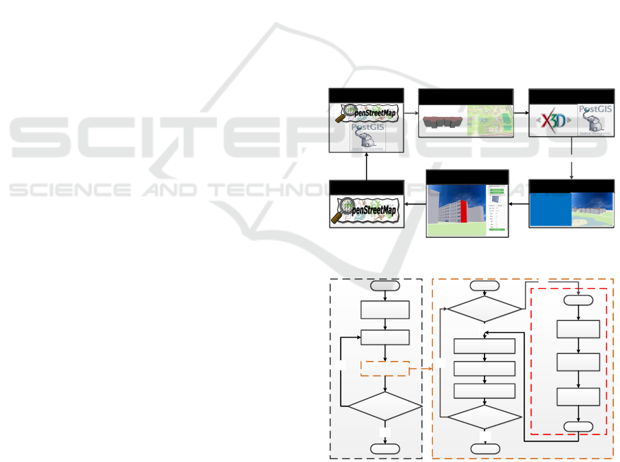
database PostGIS. Figure 1 shows the six main phases
of the system, VGI storage, model generation, model
storage, visualization, model editor and VGI genera-
tion.
The OSM data are stored in database (VGI stor-
age). Then LOD1-LOD2 3D building models are gen-
erated automatically (model generation). To reduce
the complexity of Web 3D Service, all the 3D mod-
els are stored in a 3D database (model storage). The
client asks for the 3D models from the server and ren-
ders them (visualization). The users edit the 3D mod-
els for more details. They can review the changes in
real time (model edit). Finally the detailed 3D VGI
information is generated and uploaded to the server
(VGI generation).
Model Storage
VGI Storage
VGI Generation
Model Editor
Model Generation
Visualization
Web 3D Service
x3dom
Figure 1: The methodology of the solution.
Select
building
All surfaces
edited?
Select surface
beginBegin
Select template
Begin
Select base
template
Set
parameters
Add
template
End
Yes
No
Set position
Add to the model
All details
edited?
End
Yes
Template
available?
Yes
End
No
No
Edit
building
Edit
building
Edit
surface
Edit
surface
Edit
template
Edit
template
Edit surface
Figure 2: The template based CAD methodology.
In this paper, We provide the method to gener-
ate different components of the building. A tem-
plate based CAD methodology is proposed based on
PM. There is no complex design in this methodol-
ogy, which makes it more friendly to non-professional
Massive Detailed 3D Geographic Information Collection on the Web
97
contributors. As shown in Figure 2, there are three
main parts of the CAD methodology, edit template,
edit surface and edit building. Base templates for the
detailed information are stored in the system. Tem-
plates will be generated by simply setting proper pa-
rameters to the base template. Each surface is edited
by selecting templates and setting the right relative
positions of them. When all surfaces of the building
are edited, modification of the building comes to an
end. All the operations above are only selecting com-
ponents and setting parameters for them. Any user
will be familiar with them in a few minutes.
3.2 Management of Templates
The template based CAD methodology is depending
on the templates. With more and more templates
edited, there will be an increasing problem in man-
aging the templates. Here we will introduce three
different principles of managing the templates: base
templates, user based templates and location based
templates. The managements reduce the steps for the
volunteers to edit the building by reusing the existing
templates. On the other hand, the data size will be re-
duced by merging the duplicate templates. Storage is
saved on the server side. On the client side, they prove
to be quite efficient in the following tests ( Figure 7 ).
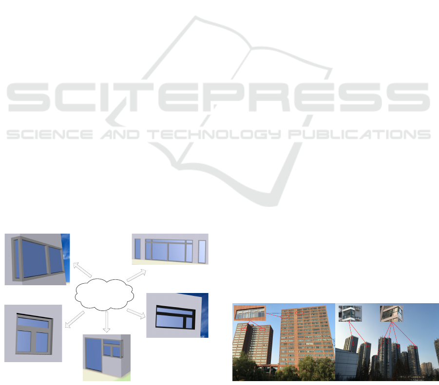
3.2.1 Base Templates
Base templates are the basis of all the templates. They
are designed and stored in the system. They represent
the base components of the buildings, such as win-
dows and doors. Base templates have the framework
of the components. A few variables are left to modify
different templates. Taking doors for example, doors
have width height and style variables. The style can
be wood or glasses. By setting these variables, the
Base
Template
Figure 3: Examples of different templates generated from
one base template and their usage in the building.
system generate different door templates. At present,
we set two simple base templates for tests. In the fu-
ture, base templates will be got from volunteers all
over the world and approved by the manager of the
system. In Figure 3 , we generate a few windows and
doors from one base template and use them to modify
the building.
3.2.2 User based Templates
User based templates is an important feature of the
system. For each user, the system will store all the
templates that have been generated or used by the
user. When a building is modified, any user is allowed
to reuse the component templates of the building. The
system allow the user to select an existing template
in the modified building and add it to his own tem-
plates store. In this way, the existing templates will
be reused and greatly simplify the work of users. On
the other hand, reusing the templates means less stor-
age of the system on the server side. One template
has only one storage on the server side. Less effort is
required to manage the templates on the server side.
This is quite important as the templates grows in the
future.
3.2.3 Location based Templates
Another important feature of the system is the lo-
cation based templates. Similar to the user based
templates, the location based templates are to reuse
the existing templates. We create this kind of tem-
plate management based on the fact of our real world.
Buildings in our world are of different styles. In many
cases, buildings in the same city or in the nearby area
have similar appearance. Their components are of the
same appearance and the same parameters (eg. width
of the door, height of the door). Examples are shown
in Figure 4. On the left are two laboratories in the
university. On the right are several buildings in the
residential area. The building components in red cir-
cle are of the same template. With the observation, we
provide the location based templates. In section Tests
and Evaluations, it is proved to be quite efficient when
the user do not have enough user based templates.
Figure 4: Examples of same templates based on location in
real world.
WEBIST 2016 - 12th International Conference on Web Information Systems and Technologies
98
The location based templates are generated by the
system without any interaction from the users. The
whole process works similar to a location based ser-
vice. When we are editing a building, the system
computes a rectangle with length and width of 2000
meters ( an experimental value ) centered at the build-
ing. Then all the buildings in the rectangle are com-
puted and selected from the OSM database. The tem-
plates used in these buildings, indexed by id, are de-
tected and ranked by the frequency used in different
buildings. At last, a list of ranked templates are re-
turned to the client side, which are the location based
templates shown in the client interface.
3.3 Data Structure of the System
Two new data structures are the key features of the
system: Editable X3D ( E-X3D ) and OSM extensions
for templates. E-X3D makes it possible to edit the 3D
model on the web while OSM extensions is designed
to represent and store the proposed templates of the
system.
3.3.1 The E-X3D Format
To be editable, three features are essential for the
3D models. Firstly, the component of the 3D mod-
els should have the feature to be selected; Secondly,
the data of the selected component can be changed;
Thirdly, these changes to the component can be syn-
chronized to the scene in real time. In (Behr et al.,
2009; Web3DConsortium, ; Behr et al., 2010), de-
tails have been introduced about how to make the 3D
model response to the users with X3D and X3DOM.
When loaded, X3D models are in the format of a
DOM tree. HTML DOM object makes it possi-
ble to select specific component by id in the DOM
tree. Leveraging these features of X3D, X3DOM and
HTML DOM object, we extend the X3D to the E-
X3D.
For building models in E-X3D, special contents
are added. Each building and each surface of the
building are grouped separately with X3D Group tag.
The Group tag of each building has one globally
unique id and each component of it has one unique
id locally. The globally unique id is created from the
OSM id of the building. Besides, An onclick function
with id as parameters is added to each Group. The
function responses operations from users. With these
extensions, the models are of E-X3D format and ed-
itable. Example of the editable building in E-X3D is
below.
<Group id = ’building_131’ onclick =
"edit_building(’building_131’);">
<Group id = ’wall_0’ onclick =
"edit_wall(’wall_0’);">
/* Content for the wall */
</Group>
/* Content for other walls and roofs */
</Group>
Wrapped in E-X3D format, the building and the
wall will be selected in the DOM tree by the specified
id on click of users. We can change the content of the
DOM tree through the HTML DOM object. At last,
changes are synchronized to the scene in real time.
3.3.2 OSM Extension for Templates
When we add the new extensions, the most impor-
tant thing is that we have to make them compatible
with the existing 2D OSM data. Following the OSM
shcema, we only use nodes, ways, relations and key-
value pairs for all kinds of data and information.
In this paper, we present a new methodology to
represent a detailed 3D building extended from the
one introduced in (Goetz, 2013). Motivated by PM,
we provide a new way to represent the 3D informa-
tion for openings of the building. We do not attach
a key-value pair tag for each parameter of the open-
ings. Instead, we divided the openings into different
styles. For each style, we design the methodology
to generate the 3D model and figure out which pa-
rameters are required. Then we give the key to rep-
resent the opening style and the parameters. In this
way, when we face a new opening style, we do only
need to design the methodology and figure out the
parameters. No more new keys is required, which
will avoid the potential key explosion in OSM. We
proposed four more keys for the 3D model of win-
dows and doors. Details are listed in 1. The tem-
plate:id key is used when the template is referenced
in the building. Information of the opening style is
represented by basetemplate:id and opening parame-
ters by basetemplate:parameters key. For example,
the two parapemters of the base template 1 represent
the height and the width of the model. When we gen-
erate a window model with basetemplate:id=”1” and
basetemplate:parameters=”3,1”, the result is a win-
Table 1: Proposed keys for detailed 3D models.
Key Description
Exemplary
Values
template it is a template yes
template:id
the reference id
of the template
1,1000
basetemplate:
id
the reference id
of base template
1, 2
basetemplate:
parameters
parameters of the
base template
”3 3 0.1”
Massive Detailed 3D Geographic Information Collection on the Web
99

dow with height of 3 meters and width of 1 meters.
The two new basetemplate keys only represent the
3D information of the template itself. The 3D infor-
mation of the template in real world is attached by
key-value pair tag when the template is used. In the
following code we show how to represent and use a
window in OSM with the extensions. The position of
the template is where the template was first created
and used. The breast of the window is attached by
tags buildingpart:window:breast when the template
is used.
<!-- representation of a template -->
<node id="224524350810" lat="31.8341438"
lon="117.2960426" buildingpart:window="yes"
template="yes" user="tom" basetemplate:id
="1" basetemplate:parameters="3,1"
/>
<!-- usage of the template in the building -->
<node id ="224524350820" lat="31.8341438"
lon="117.2960426" user="tom"/>
<tag k="template:id" v="224524350810">
<tag k="buildingpart:window:breast" v="2">
</node>
The new design is compatible with OSM. All the
data are directly stored in the OSM database. For new
3D features and more complex 3D features, we do
not need more new keys. It will avoid the key ex-
plosion when we try to represent the complex real
world in OSM. Besides, the template will be reused.
For a window template, it may be reused for tens of
times in one building, even reused for thousands of
times in the whole city. With the extended method-
ology, we reduce the effort to modify the building
component and storage on the server side by reusing
the existing template. The data with new extensions
can be transformed into OGC standard data. For each
base template, the 3D information is stored in the pa-
rameters. The methodology and principle to generate
CityGML models from the parameters are designed
ahead. Then following the principles introduced in
(Goetz and Zipf, 2011), we can generate detailed 3D
building models in CityGML format.
3.4 Principles and Precision
3.4.1 Principles
As this is a system to collect detailed 3D information
from volunteers, there is a chance that two different
persons modify the same building. It is similar to the
current 2D OSM editor. In this case, the system han-
dles the data as what the 2D OSM editor does. All the
data are stored in the database. Each data are attached
with key user and timestamp to represent the editor
and the time edited. The latest data are shown to the
user. The principle applies to both the building data
and the template data to solve potential conflicts. We
assume that the new data are to correct some errors in
the previous data. The principle proves to be simple
and efficient. At present, following this principle, the
2D OSM data are reliable (Fan et al., 2014).
3.4.2 Precision
Another problem is the precision of the collected data.
A lot of persons question the quality of the VGI
data. The problem of precision mainly comes from
two aspects. One is that the volunteers have no re-
liable methods to measure the 3D information. The
other is that the volunteer is careless and not reliable.
For the first aspect, there is a trend that mobile de-
vices are equipped with more sensors for 3D mea-
surement. A experimental device of Google Tango
project has been produced. In the future, we believe
that there will be reliable tools in mobile devices for
3D measurement. For the second aspect, experiments
have been done to evaluate the quality of the data in
OSM (Fan et al., 2014). Results show that the pre-
cision of building footprints in OSM is reliable com-
pared with the authority data in Germany. The volun-
teers are trustworthy. The 3D information from vol-
unteers is expected to be reliable.
4 IMPLEMENTATION
The target of this paper is a widely-applicable sys-
tem for detailed 3D Geographic collection. The func-
tions of this system consist of storing 3D informa-
tion on the server, visualizing low LOD 3D models
on the web, modifying the models with more details
and generating detailed 3D VGI to upload. The users
of this system - the contributors of VGI may be non-
professional and know nothing about GIS or CAD. To
achieve the target, the following features have to be
satisfied. 1. The client of the system should be imple-
mented on the web regardless of platforms. 2. There
should be an easy-to-use tool to edit the models and
review the changes.
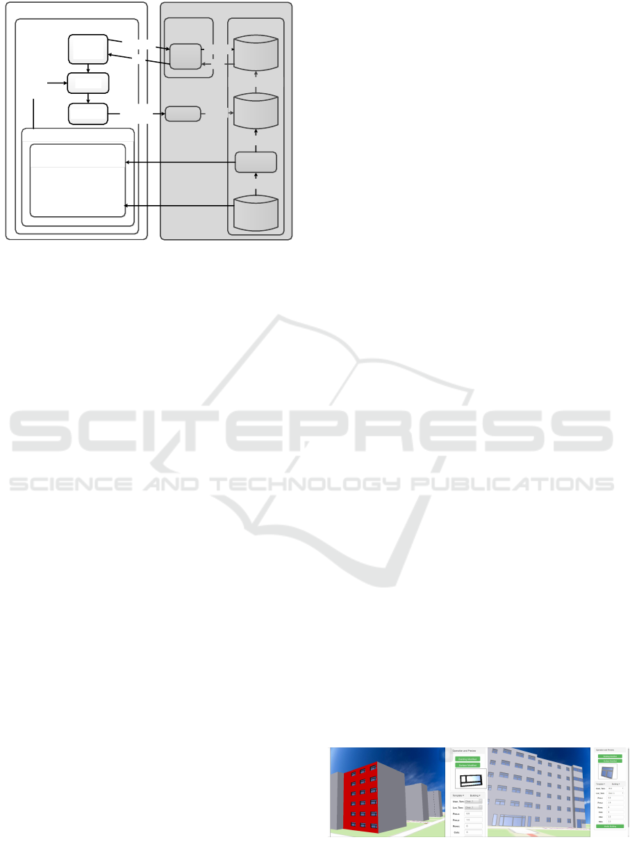
Figure 5 shows the architecture and workflow of
the system. VGI storage, model generation and model
storage are implemented on the server side, together
with the OGC standard Web 3D Service (W3DS). On
the client side, there are three components based on
X3DOM, a load manager controlling the scene to load
and rendered; an editor interacting with X3DOM to
edit 3D models and review the changes; a generator
used to generate VGI data from the operations and
upload the data to the server. The client requests low
LOD 3D models from the server through W3DS and
WEBIST 2016 - 12th International Conference on Web Information Systems and Technologies
100
Server
Data Storage
OGC Web
Service
Client
Browser
Editor
Templates
Management
VGI
Database
3D Model
Database
W3DS
Request
Acceptor
Import
Generator script
Load
Manager
Generator
OSM data
XML
Get Scene
X3D
X3DOM
Edit
changes
X3D
User
Database
Reference
1. Base Templates
2. User based templates
3. Location based
templates
Template
Data
Stored in
Figure 5: The architecture of the system.
uploads the detailed 3D information in return. De-
tailed implementation of the system is explained in
section Server and Client.
4.1 Server
The server of the system has three databases, one VGI
database to store the VGI data; one 3D database for
3D models; one user database to store the user infor-
mation. As the template data are completely compat-
ible with the OSM data, they are stored directly in the
VGI database.
The generating process from OSM data to 3D
models is quite complex. It takes too long for real
time web service. To get better performance of
the server, the 3D database is introduced .The data
streaming between VGI database and 3D database is
achieved by a generator script based on the method-
ology introduced in (Goetz, 2013). The Web 3D Ser-
vice (Schilling and Kolbe, 2010), which is an OGC
standard, is implemented to exchange 3D models be-
tween the server and the client. It gets the requests
from the client and decodes the requested data from
the databases. Then the data are generated in E-X3D
format and returned to the client.
An accepter to response the uploaded data is im-
plemented on the server. If the detailed 3D data pass
the basic correctness check, they will be imported into
the VGI database.
4.2 Client
The functions of the client consists of the followings,
visualizing the 3D models to users; editing the 3D
models with detailed information and generating de-
tailed 3D information into OSM data format to upload
to the server. These functions are achieved by load
manager component, editor component and generator
component.
The load manager controls the loading process
of the models. It calculates the square to down-
load based on the viewpoint position. The stan-
dard W3DS GetScene request is used to request 3D
models from the server. To overcome the preci-
sion problem of the floating point number of We-
bGL (Web3DConsortium, ), the load manager trans-
forms the X3D models into local coordinate built
based on the viewpoint position.
The editor interacts with X3DOM to edit the 3D
models. The template based CAD methodology is im-
plemented. In most cases, openings of the same tem-
plate in one surface distributes regularly. We leverage
this feature to simplify the operations. The users only
set two types of parameters. One is the number of
columns and rows. The other is the distance between
adjacent rows and adjacent columns. The positions
of the template are calculated by the editor. When
editing models, the editor stores the details in a DOM
tree. Then changes are calculated and added to the
X3D models. A preview window is implemented to
review the editing template or the selected template.
This will prevent some errors when editing the build-
ing.
When the building is modified, the generator com-
ponent gets the detailed 3D information from the
DOM tree structure. Then the information is trans-
formed into global coordinate and generated into
OSM data format. Finally it is uploaded to the server.
5 RESULTS AND EVALUATIONS
This paper presents a web based system to visualize,
edit and collect detailed 3D information for OSM.
Compared with other VGI projects and commercial
projects, the new system makes it possible to edit de-
tailed 3D geographic information in web based 3D
environment. The platforms to edit 3D models are ex-
tended to mobile devices. The operations to edit the
models are simplified for non-professional VGI con-
tributors. A prototype of the system is implemented
for tests.
a)
a)
b)
b)
A B
Figure 6: Editing the 3D building model on different plat-
forms. A. On Iphone6S . B. On a personal computer.
Massive Detailed 3D Geographic Information Collection on the Web
101
Tests for both computers amd mobile devices are
implemented. The result is shown in Figure 6. The
surface of the building in red color is on editing.
5.1 Performance Tests
Three types of performance tests are designed. 1.
Tests on computers and mobile devices to compare
the performance between different platforms. 2. Tests
on the same platform with different browsers to get
the influence of browsers. 3. Tests on the initial low
LOD models and the edited models to get the effect of
the editing operations on performance. For the com-
puter platform, it is a personal Lenovo computer with
CPU i5-3470 3.20 GHz. The graphical card is Nvidia
GeForce GT620. The operating system is Ubuntu
12.04 64bit. For the mobile platform, it is Iphone6s
with IOS 9.0. The browsers are Chrome 38.0 and
IOS Safari 9.0, which fully support the WebGL stan-
dard. As this paper focuses on details, ten buildings
are loaded. The size of the X3D file is 154.9KB. Ex-
tra data are 64 pictures as textures. Details of the
tests are shown in Table 1. The editing operations
add 316 templates including windows and doors to
the building model. Status initial stands for before
the editing operations. Status edited stands for after
the editing operations. The FPS is the average frame
per second when navigating the model. The system
runs smoothly on different platforms.
Table 2: Tests on different platforms.
Id Platform Browser Status FPS
1 Lenovo Chrome 38.0 initial 55.9
2 Lenovo Chrome 38.0 edited 55.6
3 Iphone6S Chrome 38.0 initial 34
4 Iphone6S Chrome 38.0 edited 32
5 Iphone6S Safari 9.0 initial 35
6 Iphone6S Safari 9.0 edited 34
There is a big performance advantage in comput-
ers compared with mobile devices (1 and 3, 2 and
4). Different browsers on the same platform have
some differences. The differences come from the ef-
ficiency of their WebGL implementations (3 and 5, 4
and 6). Considering the editing operations, there is a
slight drop in performance on mobile devices while
nearly nothing on computers (1 and 2, 3 and 4, 5 and
6). These tests show that the performance of the sys-
tem mainly depends on the platform and the browser.
The editing operations in the system will only influ-
ence the performance slightly on mobile devices. The
client runs smoothly on the web on all the tested de-
vices. Both the computers and the mobile devices can
meet the requirement of the client.
5.2 Effciency Evaluation
The number of operations to modify a building can be
calculated by Eq 1.
N = NT +
NS
∑
i=1
NT S
∑
j=1
NIR (1)
N stands for the total number of the editing opera-
tions. NT is the number of different templates of the
building. NS is the number of surfaces. NTS is the
number of different templates for each surface and
NIR is the number of irregular position modes of the
same template in one surface. The building edited in
Figure 6 B has 33 surfaces, 312 windows and 4 doors.
The variables of the building in Eq 1 are as follows,
NT is 9, NS is 33, NTS ranges from 0 to 2 and NIR
ranges from 1 to 2. The building is edited in only 43
steps.
We also evaluate the template management
method of the system. When the user has the tem-
plates to modify the building, there is no need to mea-
sure the building component and modify the template
for another time.
N =
NS
∑
i=1
NT S
∑
j=1
NIR (2)
In this case, the Eq 1 becomes Eq 2, where the vari-
ables are the same as in Eq 1. If the templates of
the building can be got, the building edited in Fig-
ure 6 can be edited in 34 steps, reduced by 21 percent.
The system requires nearly no professional knowl-
edges, which make it nearly no difference between
experienced and non-experienced users. Five non-
experienced persons are chosen to modify the build-
ing in Figure 6. They spend about ten minutes to be
familiar with the system. Then three different cases
are tested and average time cost for them are shown
in Figure 7.
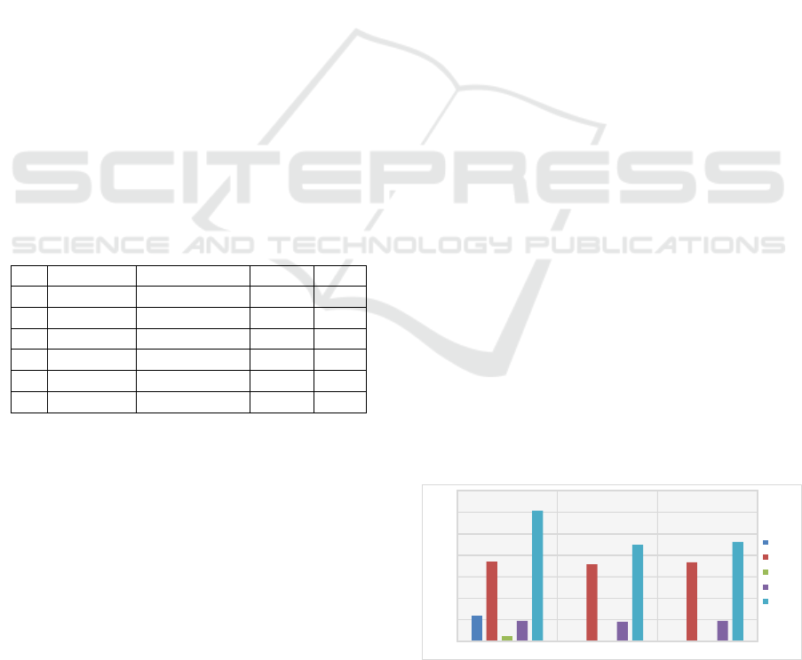
In case A, all the persons have no available tem-
plates. They have to measure the building compo-
597
0 0
1852
1785
1830
113
0 0
468
453
471
3030
2238
2301
0
500
1000
1500
2000
2500
3000
3500
A B C
TMC/s
TMB/s
TET/s
TEB/s
TT/s
Case
Figure 7: Time to modify the building. TMC, TMB, TET,
TEB, TT are time to measure the building component, time
to measure the building, time to edit the templates, time to
edit the building and total time for all of the above.
WEBIST 2016 - 12th International Conference on Web Information Systems and Technologies
102

Table 3: Comparison between different tools.
Tool CPY PR AR MM UBY
Kendzi3D YES JOSM, Kendzi3D plugin, Computers CAD skills NO Medium
OBM NO Professional CAD tool, Computers CAD skills NO Low
Our System YES WebGL browser, Computers or Mobile devices few skills YES High
nents and edit the templates. In case B, all the per-
sons have modified a similar building and they can
get all the templates from the user based templates of
the system. In case C, the persons get all the templates
from the location based templates of the system.
PercentSaved =
(OriginTime − AvgTime)
OriginTime
∗ 100
(3)
The template management methods can significantly
reduce the time to modify the building. We compute
the percentage time saved with Eq 3. OriginTime is
the time cost without any template management (time
cost in case A ). AvgTime is the average time cost
with user based template management and location
based template management ( average time cost of
both case B and case C ). Compared case B and C with
case A, 25.1 percent of time is saved for the users.
In the editing process, about 19.4 percent of time is
saved. At present, most time to modify the building is
taken by measuring the building. The time to edit the
building in our system only takes 19.2 percent of the
whole time. There is a trend that mobile devices are
equipped with more and more measurement sensors.
We believe that time for measurement of the building
will be reduced in the near future. When the measure-
ment is done, the time to modify the building with our
system is only 581 seconds, less than ten minutes.
5.3 Compared with other Related Tools
As Openstreetmap develops very fast, there are sev-
eral tools to modify 3D information for OSM. Here
we will compare our system with another two tools,
Kendzi3D and Open Building Models ( OBM ).
Kendzi3D
4
has a plugin in the Openstreetmap ed-
itor JOSM. With Kendzi3D plugin, the user can edit
the building model in a 3D environment. Besides,
compared with the traditional editing methods by just
adding key-value pair tags, kendzi3D plugin avoids
the potential modeling errors and ensures the topo-
logical consistency in complex 3D models. In fact,
Kendzi3D is a light weight CAD tool to modify 3D
building models.
Open Building Models (Uden and Zipf, 2013) is
another tool to collect detailed 3D information for
4
http://wiki.openstreetmap.org/wiki/JOSM/Plugins/
Kendzi3D
Openstreetmap. Exactly, it is an independent project
related to Openstreetmap. In OBM, the user con-
structs a detailed 3D building model with local CAD
tools. Then the user transforms the model into VRML
format. On the website of OBM, the user selects the
building in Openstreetmap and uploads the 3D model.
We evaluate the three tools. The result is shown
in table 3. CPY, PR, AR, MM and UBY are com-
patibility, platform requirement, ability requirement,
management of models and usability of the tool.
For compatibility, the data of our system, together
with Kendzi3D are in xml format, the same as Open-
streetmap data. They can be easily represented and
stored in current OSM database. The data format of
OBM is VRML, a 3D model format. In the OBM sys-
tem, an independent database is created to store the
3D data.
The platform requirement of our system is less
than the other two tools. Kendzi3D requires the
JOSM editor and the Kendzi3D plugin. For OBM,
professional CAD tools are essential. Both of their
requirements can only be met on computers with spe-
cial softwares while our system requires only a We-
bGL supported browser. At present, it can be met by
a variety of popular browsers including IE, Chrome,
Firefox
5
on not only computers but also mobile de-
vices.
To modify the building, only a few steps are re-
quired in our system. The user can be familiar with
the steps in several minutes while Kendzi3D and
OBM need professional CAD skills. Besides, con-
sidering easing the operations of the user, our sys-
tem implements template management methods. This
is proved to be more efficient in figure 7. Neither
Kendzi3D nor OBM has this feature. Every time to
modify a new building, they have to build every com-
ponent and make a fresh start.
The usability is a overall evaluation for both PR
and AR in table 3. OBM requires Professional CAD
tool for the platform and CAD skills for the user. The
usability is scored as Low. Kendzi3D requires JOSM,
Kendzi3D plugin for the platform and CAD skills for
the user. Compared with OBM, it is a light weight
CAD tool and easier to use. Its usability is scored as
Medium. Our system requires few professional skills
and the WebGL browser is supported in most plat-
5
https://en.wikipedia.org/wiki/WebGL
Massive Detailed 3D Geographic Information Collection on the Web
103

forms. The usability is scored as High.
As a conclusion, our system is very competitive
against Kendzi3D and OBM. It is compatible with the
Openstreetmap perfectly. It requires less for the plat-
form and for the user. The existing information and
data of the system are reused to simplify the opera-
tions. The system is of high usability.
6 CONCLUSIONS
The main contribution of this paper is a new sys-
tem for detailed 3D geographic information collection
through VGI. We introduce a template based CAD
methodology to edit the building. The OSM data
are extended to represent and store the template data.
Template management methods are proposed to man-
age and reuse the existing templates. When trans-
formed into OGC standard CityGML format, the col-
lected data can be widely used in a variety of applica-
tions and spatial analysis. With the widely-applicable
feature and no professional knowledge required, the
system extends the collection to mobile devices and
non-professional contributors. Collection for massive
detailed 3D geographic information will be achieved
through a large number of contributors of VGI.
In the future, more base templates will be pro-
posed to edit more complex details. We encourage
volunteers to contribute base templates for the sys-
tem. We will get a more detailed 3D world from VGI.
ACKNOWLEDGEMENTS
Thanks to the OpenStreetMap community for the free
geographic data.
REFERENCES
Arnaud, R. and Barnes, M. C. (2006). COLLADA: sailing
the gulf of 3D digital content creation. CRC Press.
Behr, J., Eschler, P., Jung, Y., and Z
¨
ollner, M. (2009).
X3dom: a dom-based html5/x3d integration model.
In Proceedings of the 14th International Conference
on 3D Web Technology, pages 127–135. ACM.
Behr, J., Jung, Y., Keil, J., Drevensek, T., Zoellner, M., Es-
chler, P., and Fellner, D. (2010). A scalable architec-
ture for the html5/x3d integration model x3dom. In
Proceedings of the 15th International Conference on
Web 3D Technology, pages 185–194. ACM.
Fan, H., Zipf, A., Fu, Q., and Neis, P. (2014). Qual-
ity assessment for building footprints data on open-
streetmap. International Journal of Geographical In-
formation Science, 28(4):700–719.
Goetz, M. (2013). Towards generating highly detailed
3d citygml models from openstreetmap. Interna-
tional Journal of Geographical Information Science,
27(5):845–865.
Goetz, M. and Zipf, A. (2011). Extending OpenStreetMap
to indoor environments: bringing volunteered geo-
graphic information to the next level. CRC Press:
Delft, The Netherlands.
Goodchild, M. F. (2007). Citizens as sensors: the world of
volunteered geography. GeoJournal, 69(4):211–221.
Kolbe, T. H., Gr
¨
oger, G., and Pl
¨
umer, L. (2005). Citygml:
Interoperable access to 3d city models. In Geo-
information for disaster management, pages 883–899.
Springer.
Marrin, C. (2011). Webgl specification. Khronos WebGL
Working Group.
Over, M., Schilling, A., Neubauer, S., and Zipf, A. (2010).
Generating web-based 3d city models from open-
streetmap: The current situation in germany. Comput-
ers, Environment and Urban Systems, 34(6):496–507.
Patow, G. (2012). User-friendly graph editing for proce-
dural modeling of buildings. Computer Graphics and
Applications, IEEE, 32(2):66–75.
Schilling, A. and Kolbe, T. H. (2010). Draft for candidate
opengis
R
web 3d service interface standard. Version
0.4. 0.
Smelik, R. M., Tutenel, T., Bidarra, R., and Benes, B.
(2014). A survey on procedural modelling for vir-
tual worlds. In Computer Graphics Forum, volume 33,
pages 31–50. Wiley Online Library.
Uden, M. and Zipf, A. (2013). Open building models: to-
wards a platform for crowdsourcing virtual 3d cities.
In Progress and New Trends in 3D Geoinformation
Sciences, pages 299–314. Springer.
Verma, V., Kumar, R., and Hsu, S. (2006). 3d building
detection and modeling from aerial lidar data. In
Computer Vision and Pattern Recognition, 2006 IEEE
Computer Society Conference on, volume 2, pages
2213–2220. IEEE.
Web3DConsortium. X3d specification. http://www.web3d.
org/documents/specifications/19775-1/V3.3/index.
html.
WEBIST 2016 - 12th International Conference on Web Information Systems and Technologies
104
