
Design Time Validation for the
Correct Execution of BPMN Collaborations
Jonas Anseeuw, Gregory Van Seghbroeck, Bruno Volckaert and Filip De Turck
Department of Information Technology, Ghent University, B-9050 Ghent, Belgium
Keywords:
Cloud Computing, Distributed Computing, Service Modeling, Collaboration, Business Process Management,
Business Process Modeling, BPMN 2.0.
Abstract:
Cloud-based Software-as-a-Service (SaaS) providers want to grow into the space of business process outsourc-
ing (BPO). BPO refers to the systematic and controlled delegation of many steps of a company’s business pro-
cess. BPO is a new and important extension to SaaS, as it allows the provider to add more value in the online
application services and as it enables the outsourcer to obtain more cost efficiency. BPO results in decen-
tralized federated workflows. To describe these workflows, companies often use business process modeling
languages. Currently, Business Process Modeling Notation (BPMN) is one of the best-known standards. It is
crucial to ascertain that the modeled workflow is executed as intended. Errors that happen during execution
of a federated workflow can come with huge costs. Validating the model is limited to syntactical checks and
there is little support for validating the execution at design time. In this paper a method is presented to validate
the correct execution of BPMN 2.0 Collaborations. The methods in this research use concepts from virtual
time previously described for Web Services Choreography Description Language (WS-CDL). To validate the
results of this research, the Eclipse BPMN modeler was extended with an implementation of the validation
method.
1 INTRODUCTION
In current competitive markets, cloud-based
Software-as-a-Service (SaaS) providers no longer
want to manage all parts of their business processes
themselves. They want to focus on their core business
activity to stay ahead of competition. By growing
into the space of business process outsourcing (BPO),
they can delegate many steps of their business
process, e.g. billing, managing e-mail or shipping
packages. For example, a company that offers
design engineering software that involves running
simulations, can resort to different service providers
that offer simulation software. BPO is a new and
important extension to SaaS, as it allows the provider
to add more value in the online application services
and enables the outsourcer to obtain more cost
efficiency.
BPO always results in decentralized federated
business process flows. With decentralized feder-
ated workflows it is important to accomplish the same
quality as with in-house business processes and en-
sure proper execution of the workflows. Errors that
happen after deploying the workflow can lead to huge
costs. Hence, it is important to detect possible execu-
tion issues during design time.
Companies often use business process modeling
languages to describe workflows. One of the best-
known standards, which already offers constructs to
model decentralized workflows by means of chore-
ographies and collaborations, is Business Process
Modeling Notation (BPMN). In this research we fo-
cus on validating the correct execution of BPMN 2.0
Collaborations. When modeling a collaboration it is
crucial to ascertain that the model will be executed as
intended. First, in some cases not every operation in
a Collaboration will be executed at runtime, despite
the fact that the designer modeled this step. Second,
when modeling the different elements in a Collabora-
tion (e.g. Events, Tasks and Message Flows between
Participants) in a certain order, this order is not al-
ways guaranteed at runtime. Finally, when designing
activities in parallel, it is not always the case they are
executed in parallel at runtime. Detecting these issues
at design time is important, since it can point to er-
rors in the workflow logic that can turn into serious
problems in a production environment.
The paper focuses on a method to validate if the
Anseeuw, J., Seghbroeck, G., Volckaert, B. and Turck, F.
Design Time Validation for the Correct Execution of BPMN Collaborations.
In Proceedings of the 6th International Conference on Cloud Computing and Services Science (CLOSER 2016) - Volume 1, pages 49-58
ISBN: 978-989-758-182-3
Copyright
c
2016 by SCITEPRESS – Science and Technology Publications, Lda. All rights reserved
49

modeled Collaboration is executed at runtime as in-
tended by the designer. Although only several BPMN
elements are currently supported, most Collabora-
tions can be modeled with only these BPMN ele-
ments. The method identifies the issues described be-
fore and provides feedback at design time.
The validation method in this research uses the
concept of time vectors, which was previously de-
scribed for WS-CDL (Van Seghbroeck, 2011). An ap-
proach similar to the tokens, introduced in the BPMN
specification (Omg et al., 2011) “as an aid to define
the behavior of a Process” is used to facilitate the im-
plementation.
The remainder of this paper is structured as fol-
lows. A more concrete use case of BPO is given in
Section 2. Section 3 gives an overview of related work
on validation methods for BPMN. Some background
on the differences between BPMN and WS-CDL is
given in Section 4. Time vectors are explained in Sec-
tion 5. Section 6 gives an overview of the validation
method. The implementation is presented in Section
7. And finally, conclusions are drawn and future work
is discussed in Section 8.
2 USE CASE: SIMULATION AS A
SERVICE
The design of complex engineering products, such
as planes and cars, commonly has a defined set and
sequence of activities (often in an interleaved se-
quence). These activities are engineering and simu-
lation activities. Engineering activities mainly rep-
resent data in- and output tasks (e.g. requirements,
design parameters, etc.) and approval/decision tasks.
Simulation activities take models and parameters as
input, and usually analyze characteristics which are
mentioned in the user-defined constraints and which
must be met. Engineering activities form a high-level
view on the process referred to as the engineering
workflow. Simulation activities are usually needed in
the course of the engineering workflow in order to val-
idate design parameters at an early stage, referred to
as the simulation workflow.
The procedure, described in Figure 1, is a collab-
oration between three companies. Company A is a
company with engineers to design and test car parts.
Companies B and C offer a simulation engine as a
service. Figure 2 shows the modeled Collaboration.
The numbers correspond to the steps of the use case
scenario.
1. The team leader (TL) of Company A sets up
a new design
2. Domain Expert Engineer (DEE) of A enters
many requirements and constraints and other
context information for the specific simula-
tion of the design
3. DEE specifies the parameters for a simula-
tion of the design
4. TL starts the design simulation
5. The engineering workflow of A contacts the
simulation SaaS of Company B
6. B provides the results to A
7. TL is notified to revisit the results
8. TL can choose to run an additional simula-
tion using the simulation SaaS of Company C
Figure 1: Steps of the Simulation as a Service use case.
3 RELATED WORK
Existing research deals with verifying the correctness
of business process models, more precisely the sound-
ness property. Soundness means that the process can
be correctly terminated and does not contain tasks
that will never be executed. The latter is similar to
the first issue mentioned in the introduction. This
soundness property was first introduced to the field of
Business Process Modeling (BPM) by (Aalst, 1998)
by translating workflows into Petri Nets and was fur-
ther perfected by (Wynn et al., 2009). Due to this,
Petri Nets are commonly used as intermediate for-
malisms by soundness verification frameworks (Mo-
rimoto, 2008). (Dijkman et al., 2008) shows how to
correspond BPMN elements into Petri Net structures.
A Petri Net can be verified with the ProM framework
(Dijkman et al., 2008). However, not all the compo-
nents in BPMN can be translated into Petri Net struc-
tures. For instance, it is difficult to define the cor-
respondence of Message Flows (Kherbouche et al.,
2013). In addition to this, the known frameworks that
verify the soundness, lack the verification of correct
order and parallel execution.
Tools known as analyzers or model checkers
(Kherbouche et al., 2013), e.g. SPIN (Holzmann,
1997) and NuSMV2 (Cimatti et al., 2002), are of-
ten used to automate the verification methods. These
model checkers can be used to verify whether busi-
ness process models satisfy properties formalized in
e.g. LTL (Linear Time Logic). The business process
CLOSER 2016 - 6th International Conference on Cloud Computing and Services Science
50
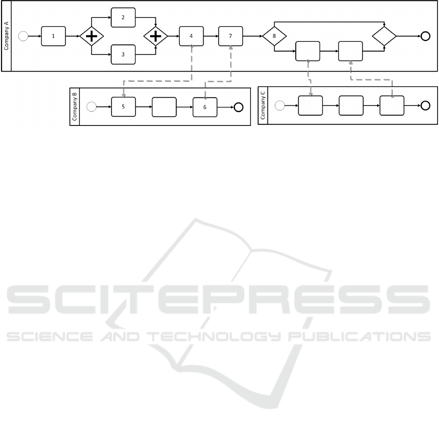
Figure 2: Relation of Engineering and Simulation Workflows. The numbers correspond to the steps of the use case scenario.
model must be described in one of the model checker
input languages, e.g. the Process Meta-Language, or
Promela, used by SPIN. Business processes can be
remodeled using Promela, with the Promela imple-
mentation then internally translated into an automa-
ton and verified. This method was used in (Solaiman
et al., 2015), but it does not support parallel BPMN
constructs and the user is required to manually enter
LTL logic to define the order that should be verified.
In contrast to this research, the presented method sup-
ports parallel BPMN constructs and no manual inter-
vention is necessary.
Different other existing frameworks are compared
in a survey (Groefsema and Bucur, 2013), however
none of them verify the order or parallel execution
of Message Flows, Tasks, Events, etc. in a Col-
laboration. (Tantitharanukul et al., 2010) checks for
deadlocks and livelocks using finite automata. (Kher-
bouche et al., 2013) transforms BPMN to Kripke
structures and used the SPIN modeler with validation
properties expressed in LTL. It validates the sound-
ness, e.g. deadlocks, livelocks and multiple termi-
nation errors. (Poizat and Sala
¨
un, 2012) transforms
BPMN to LOTOS NT process algebra.
Research initiatives that resort to well-established
process algebras, e.g. the popular π-calculus, or other
formal models, such as Promela, LTL or Chor, to vali-
date interaction protocols, are based on the formal in-
ference rules defined within the process algebra. En-
forcing these inference rules can again be handled by
model checkers (such as SPIN and NuSMV) to exe-
cute the validation. These validation efforts, however,
typically adopt a common assumption when check-
ing the ordering within the protocol. For example,
in the definition of the inference rule used to resolve
an interaction, sending and receiving a message are
considered together as one atomic action, whereas in
reality sending and receiving happen on completely
different systems.
To the authors knowledge, little research has
been conducted on validating BPMN Collaborations.
(Van Seghbroeck, 2011) presented an interesting
method to verify order of interactions in multi party
protocols. The method uses a set of ordering rules
and an extension on the concept of time vectors. The
described method was targeted at WS-CDL, but is
adapted in this research to support BPMN. Although
WS-CDL seemed a promising candidate standard at
that time, it is never really embraced by the commu-
nity. By using this vector time concept the method
presented here, does not rely on transforming BPMN
to another intermediary model. It merely conceptu-
ally annotates the BPMN Collaboration with the time
vectors.
4 BPMN VERSUS WS-CDL
Since Business Process Modeling Notation (BPMN)
is very different from Web Services Choreography
Description Language (WS-CDL), the method orig-
inated in (Van Seghbroeck, 2011) has to be adopted
to support BPMN. In this section an overview of
the most important differences between WS-CDL and
BPMN is given. BPMN is a specification where the
designer describes the different activities the partners
need to execute. These activities can lead to interac-
tions between the different partners. The sole purpose
of WS-CDL is to describe peer-to-peer collaborations
of participants by defining, from a global viewpoint,
their common and complementary observable behav-
ior. So WS-CDL is definitely not an execution lan-
guage, but it tells us how and with which messages
the distinct parties should interact.
BPMN is based on graph models to design the
flow by connecting the different elements (e.g. Tasks,
Events and Gateways) together. By connecting these
elements the designer defines the order. This is
also different from WS-CDL, which is based on
block models. WS-CDL has a Sequence, a Paral-
lel, and a Choice construct to define elements that
Design Time Validation for the Correct Execution of BPMN Collaborations
51
have to be executed sequentially, in parallel, or non-
deterministically, respectively.
Unlike WS-CDL, BPMN does not have a single
element to depict an interaction, which denotes com-
munication between participants. In BPMN interac-
tions are defined using Message Flow objects. These
Message Flows can be created between Tasks (send
and receive Tasks), between different types of Events
(throw and catch Events), and a combination thereof.
5 SUPPORTED BPMN
ELEMENTS
BPMN elements can be categorized in five categories:
Flow Objects, Connecting Objects, Swimlanes, Data
and Artifacts (Omg et al., 2011). The first three
categories are the main graphical elements to define
the workflow logic. There are three Flow Objects:
Events, Activities and Gateways. There are four ways
of connecting the Flow Objects to each other or to
other information: Sequence Flows, Message Flows,
Associations and Data Associations. Only the first
two Connecting Objects are used for workflow be-
haviour. Finally, there are two ways of grouping
the primary modeling elements through Swimlanes:
Pools and Lanes. Additional variations exists on these
basic categories (e.g. Start Event, Task, Parallel Gate-
way, etc.).
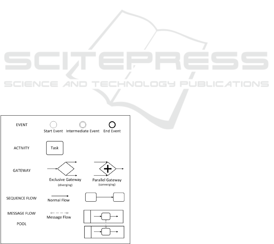
This research only supports a select set of BPMN
elements, primarily elements that define the workflow
logic (Figure 3). This restriction does not limit the
expressive power, since most BPMN Collaborations
Figure 3: A core selection of supported BPMN elements.
can be represented using only these elements (e.g. a
Service Task can be replaced by a send and receive
task).
6 EXTENDED TIME VECTORS
Introducing the concept of logical clocks and logical
time allows ordering the different executable Events,
Tasks, Message Flows, etc., further on referred as
events, in a BPMN Collaboration. This enables the
identification of issues related to parallel and correct
order of execution of events.
The first logical clocks were initially invented by
Lamport to determine the order of events in a dis-
tributed system. These clocks are a simple mecha-
nism, by which the happened before ordering (→), in
which: a → b if a must occur before b, can be cap-
tured numerically (Lamport, 1978). The original con-
cept of time vectors, which solved some issues with
Lamport’s logical time, was introduced by (Chandy
and Lamport, 1985) and (Mattern, 1988). Each pro-
cess of a distributed system has a logical timestamp,
based on vectors of timestamps (time vector). A pro-
cess increments its time vector when an event hap-
pens.
If a 9 b and b 9 a the two events may have oc-
curred concurrently. Since BPMN supports parallel
structures by means of Parallal Gateways, an extra re-
lation a k b needs to be defined, denoting that event
a and b must happen in parallel. (Van Seghbroeck,
2011) defined this extension in his work, which will
be further elaborated in the remainder of this section.
Similar to a distributed system, where each pro-
cess is equipped with a representation of virtual time
(e.g. time vectors), in a BPMN Collaboration, each
Participant P
i
has a vector V
i
= [c
1
,c
2
,...,c
n
] of length
n, where n is the total number of Participants in the
Collaboration. Each element of the time vector has
the following format: V
i
[ j] = c
j
= (t
j
,
~
X
j
). These
vector elements, further on referred as time objects,
represent the last known timestamp of Participant P
j
,
where t
j
is an integer clock value, similar to the clock
value used in regular time vectors, and
~
X
j
is a vector
of time objects. The vector
~
X
j
represents the parallel
paths from a Participant and consequently the length
of the vector is the number of parallel paths.
Each executed event makes the local time vector
of its Participant increment, i.e. a Participant P
i
in-
crements its own time object in V
i
. If the executed
event happens on a parallel path, the time object on
the parallel path is incremented.
CLOSER 2016 - 6th International Conference on Cloud Computing and Services Science
52
if
~
X
i
= [] then
V
i
[i] + 1 = (t
i
+ 1,[])
else if
~
X
i
= [c
1
,...,c
k
,...,c
m
] then
V
i
[i] + 1 = (t
i
,[c
1
,...,c
k
+ 1,...,c
m
])
end if
According to (Chandy and Lamport, 1985), when a
process sends a message, it includes its time vector
with the message. On receiving a message, the re-
ceiver combines his knowledge of time with the time
vector in the message. Sending messages is defined in
a BPMN Collaboration with its Message Flows. Sec-
tion 6.1 explains which operations are needed on time
vectors to support this mechanism. Section 6.2 ex-
plains how the extension on the time vectors is used
when traversing through Parallel Gateways.
6.1 Message Flows
In case of a Message Flow between two Participants,
the time vector of the sender and receiver are incre-
mented (because there is a send and receive event).
The receiving Participant P
r
combines its own time
vector with the time vector of the sending Participant
P
s
. This is done with the component-wise supremum
V
r
:
= sup(V
r
,V
s
), i.e. for two time vectors a and b,
sup(a, b) = c such that ∀i : c[i] = sup(a[i],b[i]). In
order to correctly evaluate the supremum of time ob-
jects, at least the ≤ ordering relation needs to be de-
fined. Here is also the comparator k defined, for de-
noting parallel time objects (Van Seghbroeck, 2011).
For two time objects a = (t
a
,
~
A) and b = (t
b
,
~
B):
• a ≤ b ⇔
(
∀ j :
~
A[ j] ≤
~
B[ j], t
a
= t
b
,
t
a
< t
b
, otherwise.
• a < b ⇔ a ≤ b ∧ a 6= b, and
• a k b ⇔ t
a
= t
b
∧ (∃ j,k : j 6= k ∧
~
A[ j] <
~
B[ j] ∧
~
A[k] >
~
B[k])
For two time vectors a and b, where a[i] = (t
a
,
~
A) and
b[i] = (t
b
,
~
B)
• a ≤ b ⇔ ∀i : a[i] ≤ b[i]
• a < b ⇔ a ≤ b ∧ a 6= b, and
• a k b ⇔ ∃i : a[i] k b[i]
Suppose in the above definitions the elements of two
parallel vectors of different lengths need to be com-
pared, the shorter of the two vectors is resized to
match the other vector and the missing elements are
set to 0.
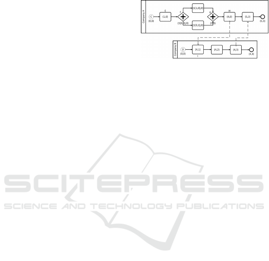
Figure 4: Use case annotated with time vectors.
6.2 Parallel Gateways
At Parallel Gateway elements, parallel time vectors
must be either created or removed. When a diverg-
ing Parallel Gateway splits the flow in the Process
of a Participant P
i
with time vector V
i
[i] = (t
i
,[]) in
multiple parallel paths. A new time vector V
f ork
,
such that: V
f ork
[ j] = V
i
[ j](∀ j, j 6= i) and V
f ork
[i] =
(t
i
,[(0,[]),...,(0,[])]). The size of the parallel vector
is equal to the number of outgoing Sequence Flows of
the Gateway. From this moment on, the events hap-
pening in a particular path k only change the k
th
time
object of this parallel time vector. When a new di-
verging Gateway occurs in the k
th
path, again a new
hierarchy level is added to the k
th
time object of the
parallel vector.
When a converging Parallel Gateway is en-
countered, a new vector V
join
is introduced, with
∀ j : V
join
[ j]
:
= sup
k
(V
i,k
[ j]). Let (t,[v
k,0
,...,v
k,m
]) be
the time object corresponding with the time object
(t
x
,
~
X) where the different parallel paths are joined
from V
i,k
[i] (it is clear that this time object is part of
V
join
[i]). The parallel paths part,
~
X, of the correspond-
ing time object is again set to the empty vector and
t
x
:
= t +
∑
j
sup
k
(v
k, j
).
6.3 Example
Figure 4 shows the Collaboration from the use case in
Section 2, but without Company C involved. It is now
annotated with the time vectors.
• Start Events C and D of Company A and B begin
with time vector (0,0). Which means both time
objects of both companies are set to 0.
• Task E increments the time vector of A.
• Gateway F adds a new parallel time vector with
size equal to the number of outgoing paths, in this
case there are two paths: (1[0,0],0).
• The task on each parallel path increments this par-
allel time vector: (1[1,0],0) and (1[0,1],0).
• Gateway G first joins both time vectors. This re-
sults in the time vector (1[1, 1], 0). Second, the
Design Time Validation for the Correct Execution of BPMN Collaborations
53
value of the time object of A is incremented with
the values of the parallel time vector, (3[0, 0], 0).
Finally the parallel time vector is again set to the
empty vector, (3, 0).
• Task H and I are both part of a Message Flow.
Conceptually, A includes its time vector with the
Message sent to B. B updates its time vector using
the time vector of A. This results in the time vector
(4,1)
7 VALIDATION METHOD
This section explains the validation method, which
is based on previous work for WS-CDL (Van Segh-
broeck, 2011). In this previous work all structures that
realize choices are removed in advance. Since it is un-
known at design time which choice will be executed,
all possible choices must be evaluated. In BPMN
this is also the case with its Exclusive Gateway ele-
ment. Taking a different path can have different con-
sequences for the events after the Exclusive Gateway.
For example, the number of Tasks and Events can dif-
fer between the different paths or a specific path can
introduce a Message Flow, so the time vector after the
Exclusive Gateway can differ according to the cho-
sen branch. Therefore, the first step in this validation
method, removes all Exclusive Gateways. This re-
sults in multiple new Collaborations, without Exclu-
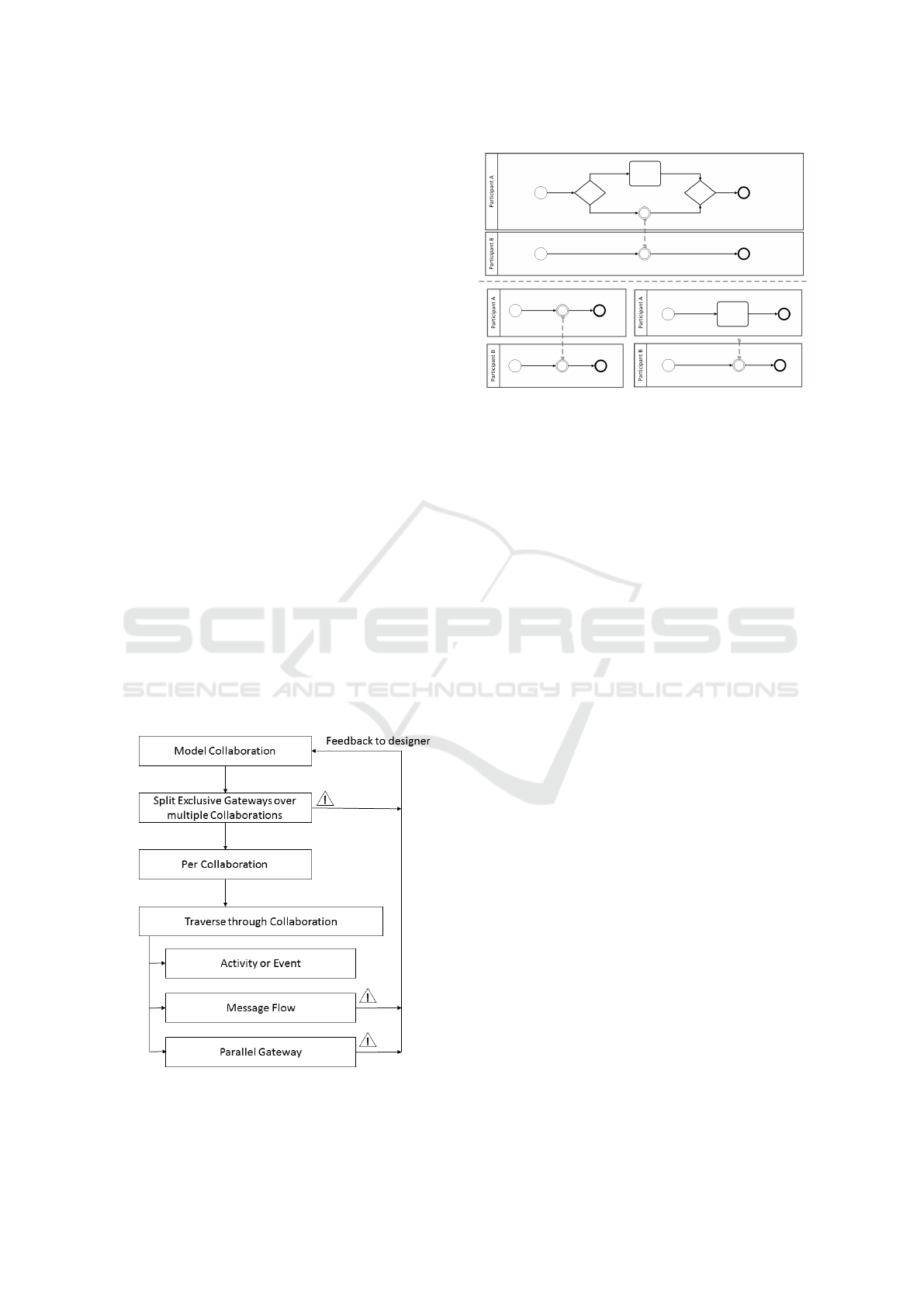
sive Gateways. This first step is depicted on Figure
5. These new Collaborations allow validating every
Figure 5: An overview of the different steps of the valida-
tion method.
Figure 6: Removing Exclusive Gateways results in 2 new
Collaborations. The bottom right Collaboration is an in-
valid Collaboration, as the Message Flow has no sending
counterpart.
possible execution path in the original Collaboration.
Splitting Exclusive Gateways over new Collabo-
rations also leads to identifying a first issue, some
BPMN elements may never be reached and thus never
get executed. Issues with parallel execution and order
can be identified by traversing through each Collab-
oration while incrementing the vector times, as de-
scribed in Section 6.
The remainder of this section illustrates the three
different issues: soundness of a Collaboration (Sec-
tion 7.1), parallel execution of Events and Tasks (Sec-
tion 7.3) and order of Message Flows (Section 7.2).
7.1 Validation of Soundness of the
Collaboration
Figure 6 shows a Collaboration between two Partici-
pants. One of the Participants can either execute the
Task or the Event. By splitting the original collabo-
ration, two new Collaborations are created, one with
the Participant A choosing the Task and one with the
Participant A choosing the Event.
In Figure 6 it is clear that the Collaboration is in-
valid. Participant A choosing for the Event (bottom
left) can result in a valid execution, but when Partici-
pant A chooses for the Task this creates a serious is-
sue: Participant B will keep on waiting for a message
to arrive. Therefore the entire Collaboration is faulty
and cannot be executed as intended by the designer,
an error should be thrown.
7.2 Validation of Order of Message
Flows
When encountering a Message Flow, The receiving
Participant combines its knowledge about the time
CLOSER 2016 - 6th International Conference on Cloud Computing and Services Science
54

Figure 7: The order of interactions on the left collaboration
is invalid. A solution is given in the right collaboration.
with the time vector of the sending Participant. Nev-
ertheless, if the receiving Participant time object is
different than the knowledge the sending Participant
vector clock has about the receiving Participant time
object, the order can not be verified.
The Collaborations depicted in Figure 7 show an ex-
ample of an invalid Message Flow and a possible so-
lution.
7.3 Validation of Parallel Execution of
Tasks and Events
To validate if Events and Tasks are executed in par-
allel, there must not be an order in them. In Figure
8 it is clear that C and D happen in sequential order
(C < D). Due to the interactions between the two Par-
ticipants, events A and B, are executed in order as well
(A < B), in contrary to what the designer modeled.
Since the relation “||” is not transitive, all the
Events and Tasks of the parallel paths need to be com-
pared two by two. But, because the elements on each
path are ordered, it is sufficient to compare the first
and last elements.
8 IMPLEMENTATION
An existing modeling tool is extended with an im-
Figure 8: Event A and B in the Collaboration are modeled
as parallel events, but are at runtime executed sequentially.
plementation of the validation method (Section 8.1).
Section 8.2 gives a breakdown of the method with cor-
responding pseudo code.
8.1 Existing BPMN 2.0 Tooling
There already exists different BPMN modeling tools.
RedHat with its jBPM (Red Hat, 2015a), an open-
source workflow engine written in Java that can ex-
ecute business processes described in BPMN 2.0, of-
fers a web based BPMN2.0 modeler (Red Hat, 2015b)
and an Eclipse plugin. However, both tools only sup-
port a subset of the BPMN 2.0 specification and ad-
ditional elements specific for jBPMN. The jBPMN
Eclipse plugin is an extension of a generic BPMN
2.0 compatible Eclipse plugin developed by Eclipse
(Eclipse, 2015). Other initiatives also extend this
Eclipse plugin, e.g. Camunda (Camunda, 2015),
Imixs-Workflow (Imixs, 2015) and Activiti (Activ-
iti, 2015). These initiatives complement the Eclipse
plugin with extensions for respectively Camunda-
BPMN, Imixs-BPMN and Activiti. We also choose
to extend the generic Eclipse BPMN2 modeler.
In the Eclipse modeler validations are limited to
syntactical checks, but it is possible to include custom
validations. We extended the Eclipse Modeler with
custom validation classes that implement the afore-
mentioned validation method. The error mechanism
of the Eclipse plugin is used to provide feedback to
the designer.
8.2 Breakdown of Validation Method
Throughout the validation method, a concept of cur-
sors is used. Think of cursors moving along Sequence
Flows and passing through the different Flow Ele-
ments in the Process of a Participant. This is similar
to the concept of tokens, which is introduced in the
BPMN specification as a theoretical concept “as an
aid to define the behavior of a Process” (Omg et al.,
2011). A Process is instantiated by the Start Event
producing a token. This token then traverses through
the Flow Elements until it is eventually consumed by
the End Event. This flow of tokens represents the
execution semantics of BPMN models, i.e. the flow
describes how a process engine would execute the
model. The validation method in this research can
easily be integrated in tooling that support the token
mechanism.
Before validating the Collaboration, all Exclusive
Gateways must be removed. To remove these Gate-
ways, a depth first traversal, following the Sequence
Flows, starting from the Start Event, will result in all
possible paths (algorithm 1).
Design Time Validation for the Correct Execution of BPMN Collaborations
55

Algorithm 1: Removing Exclusive Gateways.
procedure REWRITE(process)
2: StartEvent startEvent ← process.startEvent
new List processes
4: new Process p
processes.add(p)
6: V ISIT (startEvent, p, processes)
return processes
8: end procedure
procedure VISIT(e, p, L)
10: p.add(e)
if e is End Event then
12: return
else if e is Gateway then
14: if e is Exclusive Gateway then
L.remove(p)
16: for all outgoing Sequence Flow sf do
Process p
0
← p
18: L.add(p
0
)
e ← s f .targetRe f
20: V ISIT (e, p
0
,L)
end for
22: else if e is Parallel Gateway then
for all outgoing Sequence Flow sf do
24: e ← s f .targetRe f
V ISIT (e, p, L)
26: end for
end if
28: else
e ← moveNext(e)
30: V ISIT (e, p, L)
end if
32: end procedure
After splitting the original Collaboration up into
different Collaborations without Exclusive Gateways,
the validation method continues for each individual
Collaboration as described by Algorithm 2.
Algorithm 2 uses as few data structures:
• C is a list of cursors traversing through the differ-
ent Processes in the Collaboration.
• V is a map to map each cursor to a time vector.
• SEND and RECV are maps that contain the Flow
Nodes that are respectively sending and receiving
a Message, mapped to their corresponding Mes-
sage Flow.
• G is a map to map each Process to a stack with
Gateway elements.
The map G is used to validate parallel execution of
Events and Tasks. When a converging Gateway joins
the parallel paths, both the converging Gateway and
the diverging Gateway that initially created the par-
allel paths are needed for the validation method (to
compare the order of the first and last elements).
Therefore, every time a cursor traverses through a di-
verging Gateway, the Gateway is pushed on the stack.
Popping the last Gateway off the stack, when encoun-
tering a converging Gateway, returns the other diverg-
ing Gateway. The SEND and RECEIV E maps makes
it easier to look up Flow Elements that are part of a
Message Flow and find their counterpart via the Mes-
sage Flow.
First, all cursors are set on the Start Events of the dif-
ferent Processes. The cursor traverses over the Flow
Elements, incrementing the time vectors, until the
cursor is on either a (divering or converging) Paral-
lel Gateway or a Flow Node that is part of a Message
Flow (lines 3-8 in Algorithm 2).
When a cursor reaches a Flow Node that is part
of a Message Flow, before moving the cursor further,
both the sending and receiving Participant its cursor
has to reach the sending or receiving Flow Element
(lines 9-19 in Algorithm 2).
If the cursor reaches a diverging Parallel Gateway,
the cursor will be duplicated over the different outgo-
ing Sequence Flows leaving the Gateway (lines 20-26
in Algorithm 2).
When a cursor reaches a converging Parallel Gate-
way, it has to first wait until all cursors of the in-
coming Sequence Flows ending in the Gateway, have
reached the Gateway. Then, a check is done to val-
idate if the events in the parallel paths are executed
in parallel, and finally, a single cursor will leave the
Gateway (line 28-37 in Algorithm 2).
Feedback to the designer is provided by throwing
exceptions. This happens on line 12 and 32 when
a Message Flow causes an ordering issue and when
Events and Tasks are not properly executed in paral-
lel respectively.
9 CONCLUSIONS AND FUTURE
WORK
Business Process Outsourcing (BPO) is an interesting
way for companies to again focus on their core busi-
ness. In contrast to in-house business processes or
most SaaS offerings, BPO always result in decentral-
ized federated workflows. Designing such workflows
is very difficult, especially with regard to soundness
and correctness. In order to ensure a Collaboration
is executed as modeled by the designer, we have pre-
sented a method to validate the correct execution of
BPMN 2.0 Collaborations at design time.
CLOSER 2016 - 6th International Conference on Cloud Computing and Services Science
56

Algorithm 2: Validation of a Collaboration (without Exclu-
sive Gateways).
Require: C,V, SEND, RECV,G
while ¬(∀C reached End Event) do
2: for all cursor c do
while hasNext(c) ∧ ¬(SEND(c) ∨
RECV (c) ∨ c is Gateway) do
4: if ¬(c is Start Event ∨ End Event)
then
increment V
c
6: end if
c ← moveNext(c)
8: end while
if c is send/recv then
10: if recv/send counterpart reached then
if ¬val msg f low(send, recv) then
12: Throw Exception
end if
14: increment V
send
increment V
recv
16: V
receiver
← sup(V
send
,V
recv
)
moveNext(c
send
)
18: moveNext(c
recv
)
end if
20: else if c is diverging Gateway then
G
c
.push(c)
22: for all outgoing Sequence Flow do
Cursor c
0
← c
24: C.add(c
0
)
moveNext(c
0
)
26: end for
C.remove(c)
28: else if c is converging Gateway then
if all cursors reached gateway then
30: g ← G
c
.pop()
if ¬validate parallel(g,c) then
32: Throw Exception
end if
34: c ← join(c
0
,...,c
k
,...,c
m
)
moveNext(c)
36: end if
end if
38: end for
end while
The validation method is based on previous research
for WS-CDL. The method evaluates the soundness of
a Collaboration and the order and parallel execution
of Events, Tasks and Message Flows. For a proto-
type implementation, the BPMN Eclipse plugin is ex-
tended to support the validation method. Feedback
to the user is provided by using Eclipses error mecha-
nism. In this way the designer is notified when the de-
centralized workflow contains problems, all in a real-
time fashion, during the design phase.
Currently the prototype only supports the basic
BPMN modeling and a few extended modelling el-
ements. Although this set of elements is sufficient to
describe most Collaborations, future versions of the
tool will allow all BPMN 2.0 elements. For most
elements this will mean translating the extended ele-
ments to the basic set of BPMN constructs part. Next
to this, future work also holds, implementing addi-
tional validation methods, mainly focused on the data
flow.
ACKNOWLEDGMENTS
The iMinds D-BASE project is co funded by iMinds
(Interdisciplinary Institute for Technology), a re-
search institute founded by the Flemish Government
with project support of the IWT.
REFERENCES
Aalst, W. V. D. (1998). The application of petri nets to
workflow management.
Activiti (2015). Activiti Modeler. http://activiti.org.
Camunda (2015). BPMN tool for process modeling - Ca-
munda Modeler. https://camunda.org/bpmn/tool.
Chandy, K. M. and Lamport, L. (1985). Distributed snap-
shots: Determining global states of distributed sys-
tems. ACM Trans. Comput. Syst., 3(1):63–75.
Cimatti, A., Clarke, E. M., Giunchiglia, E., Giunchiglia,
F., Pistore, M., Roveri, M., Sebastiani, R., and Tac-
chella, A. (2002). Nusmv 2: An opensource tool for
symbolic model checking. In Proceedings of the 14th
International Conference on Computer Aided Verifi-
cation, CAV ’02, pages 359–364, London, UK, UK.
Springer-Verlag.
Dijkman, R. M., Dumas, M., and Ouyang, C. (2008). Se-
mantics and analysis of business process models in
bpmn. Inf. Softw. Technol., 50(12):1281–1294.
Eclipse (2015). Eclipse BPMN2 Modeler. https://
www.eclipse.org/bpmn2-modeler.
Groefsema, H. and Bucur, D. (2013). A survey of formal
business process verification: From soundness to vari-
ability, page 198203. SciTePress.
Holzmann, G. J. (1997). The model checker spin. IEEE
Trans. Softw. Eng., 23(5):279–295.
Imixs (2015). Imixs Workflow Modeler.
http://www.imixs.org/modeler.
Kherbouche, O., Ahmad, A., and Basson, H. (2013). Us-
ing model checking to control the structural errors in
bpmn models. In Research Challenges in Informa-
tion Science (RCIS), 2013 IEEE Seventh International
Conference on, pages 1–12.
Lamport, L. (1978). Time, clocks, and the ordering
of events in a distributed system. Commun. ACM,
21(7):558–565.
Design Time Validation for the Correct Execution of BPMN Collaborations
57

Mattern, F. (1988). Virtual time and global states of dis-
tributed systems. In Parallel and Distributed Algo-
rithms, pages 215–226. North-Holland.
Morimoto, S. (2008). A survey of formal verification for
business process modeling. In Bubak, M., van Albada,
G., Dongarra, J., and Sloot, P., editors, Computational
Science ICCS 2008, volume 5102 of Lecture Notes
in Computer Science, pages 514–522. Springer Berlin
Heidelberg.
Omg, O. M. G., Parida, R., and Mahapatra, S. (2011). Busi-
ness Process Model and Notation (BPMN) Version
2.0. Business, 50(January):170.
Poizat, P. and Sala
¨
un, G. (2012). Checking the realizabil-
ity of bpmn 2.0 choreographies. In Proceedings of
the 27th Annual ACM Symposium on Applied Com-
puting, SAC ’12, pages 1927–1934, New York, NY,
USA. ACM.
Red Hat (2015a). jbpm - open source business process man-
agement - process engine. http://www.jbpm.org.
Red Hat (2015b). Web-based bpmn2.0 designer for jbpm.
https://github.com/droolsjbpm/jbpm-designer.
Solaiman, E., Sun, W., and Molina-Jimenez, C. (2015). A
tool for the automatic verification of bpmn choreogra-
phies. In Services Computing (SCC), 2015 IEEE In-
ternational Conference on, pages 728–735.
Tantitharanukul, N., Sugunnasil, P., and Jumpamule, W.
(2010). Detecting deadlock and multiple termina-
tion in bpmn model using process automata. In Elec-
trical Engineering/Electronics Computer Telecommu-
nications and Information Technology (ECTI-CON),
2010 International Conference on, pages 478–482.
Van Seghbroeck, G. (2011). Design-time validation and ex-
ecution of service choreographies. PhD thesis, Ghent
University.
Wynn, M., Verbeek, H., van der Aalst, W., ter Hofstede, A.,
and Edmond, D. (2009). Business process verifica-
tion finally a reality! Business Process Management
Journal, 15(1):74–92.
CLOSER 2016 - 6th International Conference on Cloud Computing and Services Science
58
