
Towards a Reference Architecture for Advanced Planning Systems
Melina Vidoni and Aldo Vecchietti
Ingar Instituto de Desarrollo y Diseño, CONICET-UTN, Avellaneda 3657, Santa Fe, Argentina
Keywords: 4+1 View Model, Advanced Planning Systems (APS), Functional Requirements, Reference Architecture.
Abstract: Advanced Planning Systems (APS) are important for production companies that seek the optimization of its
operations. However there are gaps between the companies’ needs and its implementation in the Enterprise
Systems, such as the lack of a commonly accepted definition, the short insight on its software architecture,
and the absence of Software Engineering (SE) approaches to this type of system. Consequently, it is
important to study APSs from a SE point of view. The motivation of this work is to present a Reference
Architecture for APS, providing a standard-based characterization and a framework to simplify the design,
development and implementation of APS. Therefore, two views are presented, which are based on the "4+1"
View Model endorsed by the international standard ISO/IEC 42010:2011; those Views are represented
using UML diagrams and they are described including variation points for a number of possible situations.
1 INTRODUCTION
Advanced Planning Systems (APS) are part of many
organizations and are linked to the Enterprise
Systems (ES) aiming to optimize raw materials,
inventory, production plans, etc., to improve the
economy of the company (Stadtler, 2005).
Some high-end ERP (Enterprise Resource
Planning) offer extra modules to perform APS
functionalities customized and adapted to each
business. Examples are SAP APO (Advanced
Planning and Optimization) (Stadtler, et al., 2012),
and Oracle ASCP (Advanced Supply Chain
Planning) (Oracle, 2015). However, on small and
medium enterprises the most common
implementation approach is an ad-hoc development,
performed inside the house or outsourced.
Thus, there is interest on a better understanding
of several issues related to the development of APS
(Zoryk-Schalla, et al., 2004), such as the lack of
standardization in associated concepts (Kallestrup, et
al., 2014; Aslan, et al., 2012; Hvolby & Steger-
Jensen, 2010), and the lack of SE approaches
(Henning, 2009; Framinan & Ruiz, 2010).
Recently, Vidoni and Vecchietti (2015) proposed
an APS characterization, by applying a SE approach,
and elicited Functional Requirements (FR) and
Quality Attributes (QA) from the academic literature
which is used to elaborate a Reference Model for the
Software Architecture (SwA) of an APS.
Still, a Reference Model is a starting point and
needs to be upgraded into a Reference Architecture
(RA) (Northrop, 2003). The latter are abstractions of
specific SwA for a given domain, and are used as
standardized frames or tools (Angelov, et al., 2012).
There are many researches about RA. Norta et al.
(2014) introduced one for Business-to-Business
systems, for research and industrial applications.
Pääkkönen et al. (2015) proposed a RA for big data
systems, based on the analysis of architectures
previously implemented. Behere, et al. (2013)
announced a RA for cooperative driving on modern
vehicles with a minimally invasive model. Finally,
Nguyen et al. (2011) developed a RA based on the
“4+1” View Model, to define agent-based systems.
This work proposes the first two views towards a
RA for the APS, based on the “4+1” View Model
(Kruchten, 1995), recommended by the international
standard ISO/IEC 42010:2011 (2011). The work is
based on the FR and the Reference Model proposed
in a previous work (Vidoni & Vecchietti, 2015). A
comparison of the FR with leading commercial
suites is summarized, to prove its applicability.
This paper is structured as follows. Section 2
introduces concepts and definitions, and Section 3
presents the FR elicited for APS, comparing them to
features of leading commercial suites. Section 4
introduces the RA concepts, standards and design
decisions, describing two views. Finally, Section 5
presents conclusions and related future works.
Vidoni, M. and Vecchietti, A.
Towards a Reference Architecture for Advanced Planning Systems.
In Proceedings of the 18th International Conference on Enterprise Information Systems (ICEIS 2016) - Volume 1, pages 433-440
ISBN: 978-989-758-187-8
Copyright
c
2016 by SCITEPRESS – Science and Technology Publications, Lda. All rights reserved
433

2 CONCEPTS AND DEFINITIONS
A definition for APS is the one given by Stadtler
(2015), which states: “Although an Advanced
Planning System (APS) is separated into several
modules, effective information flows between these
modules should make it a coherent software suite.
Customizing these modules according to the specific
needs of a supply chain requires specific skills, e. g.
in systems and data modeling, data processing and
solution methods. APS do not substitute, but
supplement existing ERP”.
This paper will also use the concept of factory
planning (which includes several types of planning
mostly at short-term) and supply chain planning
(represents factory planning problems beyond the
company limits, at mid and long term time horizons)
introduced by (Fleischmann & Koberstein, 2015).
There are also other definitions considered:
Enterprise Systems (ES), includes ERPs,
transactional systems and other information
systems that manages data in an organization
(Davenport & Brooks, 2004).
Solving Approach (SA), an umbrella term that
refers to the advanced methods and technics
used to solve advanced planning problems.
Includes operations research, genetic
algorithms, game theory, and others.
Optimization Point (OP) is a specific planning
problem solved through an APS.
Model is a specific solution for an individual
factory planning problem, using any SA.
Objective is what the model seeks to optimize.
3 FUNCTIONAL
REQUIREMENTS
Based on Software Engineering Body of Knowledge
(BKCASE Editorial Board, 2014), the Functional
Requirements of a system “[…] describe
qualitatively the system functions or tasks to be
performed in operation; FR defines what the system
must be able to do or perform”.
Since this is a high abstraction level definition,
there are no explicit stakeholders, and the hardware
to be used in the architecture is undefined.
Therefore, requirements were extracted from the
academic literature related to APS, where they are
usually presented as general statements and ideas.
Vidoni and Vecchietti (2015) introduced a list of
generic FR elicited from the academic literature, and
based on a number of international SE standards.
These FR are descripted on Table 1, where each row
represents a new requirement, with an ID code (first
column at the left) later used as reference.
However, these FR are generic, suitable for a
wide definition that can work as a frame (Angelov,
et al., 2008). Therefore, not all of them must be met
by each application of APS, because those specific
implementations are sub-sets, carefully selected for
those situations; new requirements can also be
added, because a software intensive system never
ceases to evolve and change.
Since leading proprietary suits are developed
through several iterations and continuously refined,
they implement many of the features characteristics
of APSs, contributing to the “best practices” idea of
leading ES. Therefore, by comparing the proposed
FR, it can be seen that there is a high level of
agreement, which supports their applicability, and
provides the fundaments to develop the RA.
The selected commercial applications are leaders
in the ERP market: APO (Advanced Planning and
Optimization) for SAP ERP (Stadtler, et al., 2012),
and ASCP (Advanced Supply Chain Planning) for
Oracle e-Business (Oracle, 2015). Both of them are
available as separated modules of their ES solutions,
and have available online documentation.
Evaluating SAP APO reveals a high match of the
application’s features to the FR. APO works with
two planning levels: Supply Network Planning
(SNP) is midterm/long term planning, while
Production Planning/Detailed Scheduling is short
term, similar to the factory and supply chain
planning concepts introduced before.
SNP module optimizes several OP, allowing
selecting the SA and model versioning, changes and
adaptation. Users can optimize while working on the
system in parallel; results are in friendly manner and
include historical data. As input data APO uses
demand planning, sales orders, and even ETO,
transferred from SAP ERP via the Core Interface;
the approved output data is also stored on the ERP,
while the other is kept on the APO’s own database.
APO checks consistency and bottlenecks, and
evaluates rescheduling (Stadtler, et al., 2012).
By studying Oracle e-Business ASCP features, it
is clear that this suite reinforces them, with a
different approach than SAP APO, considering
Usability as one of the main QA of the system.
ASCP allows several OP and models, with
management functions including many settings
Each model has available objectives, and
parameters management. Each planner (user) can
configure the interface, while the Planner
Workbench offers scenario comparison. ASCP uses
ICEIS 2016 - 18th International Conference on Enterprise Information Systems
434
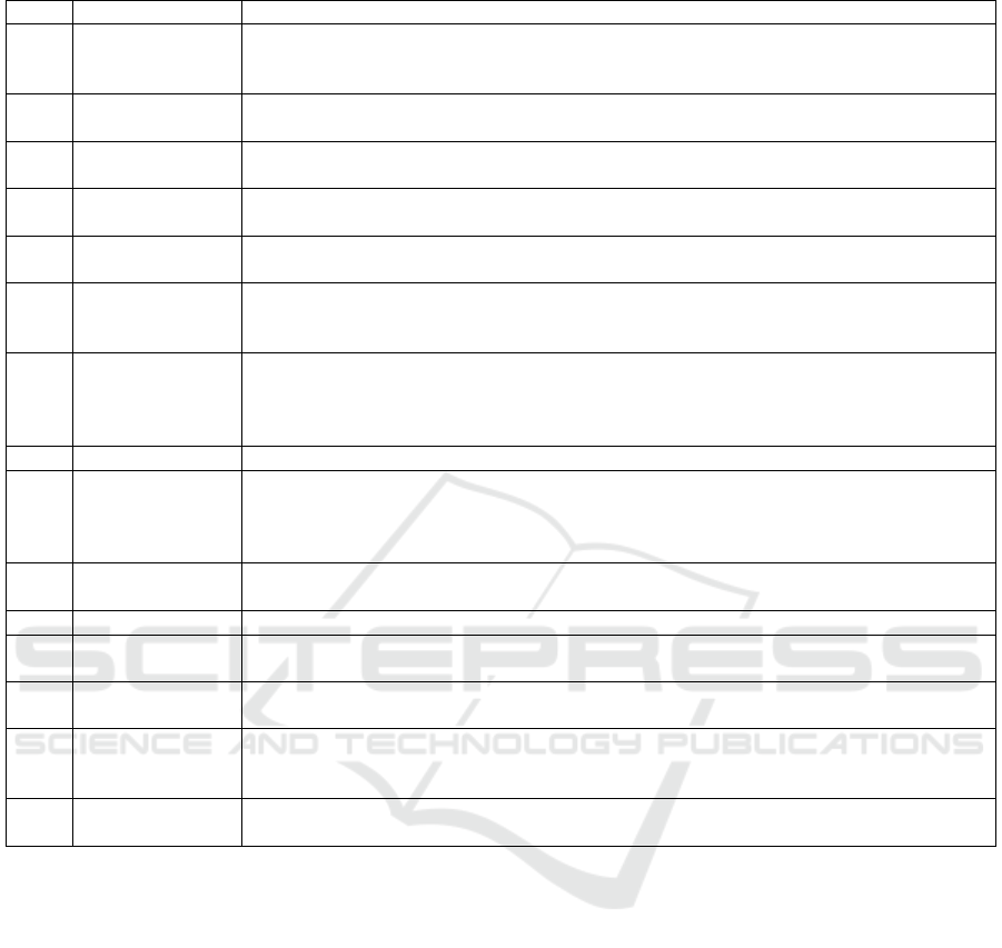
Table 1: Summary of Functional Requirements (Related to the System) for an APS (Vidoni and Vecchietti, 2015).
Code Requirement Requirement Description (Related to the System)
A Optimization
Point
Management
The system must have at least one Optimization Point, and there is no limit to how many
may optimize. The user must be able to select which Point to work with at any given time.
Each OP (which represents a planning problem) has at least one model that solves it.
B Models
Management
The system must allow the user to easily select the model to be used on each OP. If there is
more than one model, the APS should have a default, if nothing else was selected.
C Objectives
Management
The system allows the user to select the objective to use with each model. Each model
must have a default objective that will be used in case no other one was manually selected.
D Parameters
Settings
The system must offer a graphical way for the user to customize the parameters (changing
values, ranges and increments). In case no value was changed, it must use the defaults.
E Scenario
Generation
After the used input of the parameters, the APS must automatically generate each scenario,
showing progress to the user and allowing them to continue with other tasks.
F Scenario Storage The scenarios results must be automatically stored (in either success or failure/infeasibility
situations) on the APS database, to be later revised and studied by the human planner.
Results are only impacted on the ES once the user approves them.
G Scenario
Comparison
The system must offer a Graphical Interface (GUI) to compare scenario results and allow
the planner user to modify them. For successful cases the comparison should show charts,
graphics, statistics of resolution times, and so on. For unfeasible results, the showcased
information must help the planner to understand why the model turned unfeasible.
H Input Data The APS must automatically read the input data for each model from the ES.
I Consistency
Check
There must be an evaluation of the data entered on the system before running each model.
This checks the existence of needed resources, including availability of raw materials,
comparing Bills-of-Materials to current stock, machine states, and so on. If the check fails
it means that the solution was possibly unfeasible, and it must be informed to the planner.
J Output Data The system translates the results of the selected scenario to a format understood by the ES,
and stores it on it. This is only done when approved by the user.
K Log-in Function The APS restricts access to authorized-only personnel.
M Open/Saving
Results
The system should be able to open and show previous results with the same charts,
graphics and displays used before, during the comparison.
N Algorithm
Integration
An authorized user must be able to perform CRUD (Create, Read, Update, Delete) actions
for the components (models, objectives, parameters values) of each optimization point.
O Bottleneck
Detection
The system should check bottlenecks and under-loaded resources, with the aim of avoiding
proposing a planning that is not optimal regarding the use of resources. If any issue is
detected, it must be penalized and/or informed to the user, awaiting their input.
Q Rescheduling
Checking
After a deviation from the plans, the system should show whether the current jobs have to
be rescheduled. This should be decided by the human planner, or an automatized option.
any input data synchronized from any ES (forecasts
through an external module, sales orders and ETO
data), and allows deciding where to store the output
data. It also provides bottleneck detection (Oracle,
2015).
4 REFERENCE ARCHITECTURE
In SwA, Reference Model (RM) is a division of
functionalities with data flow between pieces,
working as a standard decomposition of a known
problem. Then, a RA is a RM mapped onto software
elements that cooperatively implement the FR, and
the data flows between them (Northrop, 2003).
An RA is presented with standardized diagrams
that describe it through a number of viewpoints,
fulfilling the needs of different stakeholders; these
abstract the detail of implementation, detailing
relations between components (Yonghua Zhou, et
al., 2004). However, their generic nature leads to
less defined contexts, increasing the design
complexity; consequently, it is a non-trivial matter,
surrounded by ambiguity (Angelov, et al., 2012).
The ISO/IEC 42010 (2011) standard enforces the
application of viewpoints to clarify different
approaches in a system description through a RA. In
particular, Annex B recommends the "4+1" View
Model (Kruchten, 1995), selected for this work. It
consists of four views (Logical, Development,
Process, Physical) and the "+1" represents
Scenarios, based on the FR. Since the model allows
the use of any standardized diagram, UML 2.x
(Object Management Group, 2013) is selected due to
its widespread use. Since there is no direct match
between diagrams and views, this work will follow
the associations presented in other papers (Nguyen,
Towards a Reference Architecture for Advanced Planning Systems
435
et al., 2011; Kontio, 2008).
Because this is a work in progress, only two
views are presented, with the documentation pattern
by Bachmann, et al. (2003): introduction with UML
diagram, a description of elements and relations, a
variability guide and an architectural background.
The latter adds variation points to allow variability
in the RA, to accomplish modifications in pre-
planned ways, adding changes during development
in specific study cases (Clements, et al., 2010).
4.1 Logical View
This view supports the FR, showing what the system
should provide as services to its users (Kruchten,
1995); the elements are “key abstractions"
manifested as objects, components or packages
(Northrop, 2003). This is the first view developed,
and is translated from the FR and RM of a previous
work (Vidoni & Vecchietti, 2015).
4.1.1 Primary View
Fig. 1 presents the Logical View for the RA, using a
Model Diagram. This is an auxiliary UML structure
diagram that shows an abstraction or specific view
of a system, describing its architectural, logical or
behavioural aspects (Object Management Group,
2013). Model Diagrams uses Package Diagram
syntax, and represents logical aspects of the layered
APS system, and the actors that relate with it.
4.1.2 Architecture Background
Table 2 shows a match between the FR and the
blocks of the RM (Vidoni & Vecchietti, 2015), to
Figure 1: Model Diagram for the Logic View of the APS-RA.
ICEIS 2016 - 18th International Conference on Enterprise Information Systems
436
the packages of the Logic View. The FR are grouped
considering their relations, their need to interoperate,
or if they are part of a bigger workflow. Both
databases (APS’s and ES’s) are actors, along with
the Model System, which represents a variation
point. The Logic View has new packages, added in
order to clarify the sorting of the FR, providing more
helpful blocks to the view stakeholders.
For example, Scenario Manager represents many
FR (by code: F, G, M, and the automation of the
solving in ‘Scenario Generation’). It represents a
breakdown of the RM block ‘Scenario Manager’,
and is essential for an APS. Also, the RM Factory
Planning block (along with the FR coded as A, E
and N) translates to the new Factory Planner, which
is composed of: Solving Core, Data Manager and
Configuration Manager.
4.1.3 Element Catalogue
There are five actors: Users (human planers and
decision makers that use the APS), APS Data Source
(the APS database, mentioned on some FR), ES
Data Source (ES-DS, represents the ES database,
and is mentioned on a many FR), ES Data Exchange
Interface (ES-DEI, represents an optional interface
provided by the ES for database access) and Model
Solver (MS, represents external systems that solves
models of any SA, providing raw results).
A, example of ES-DEI is the Core Interface used
by SAP APO to exchange information with SAP
ERP (Stadtler, et al., 2012). Also, the cardinality
(1..) in indicates that there can be multiple
instances of this actor, and the amount is not directly
related to how many OP exists within the APS.
APS is composed of three main layers
(Presentation, Scheduler, Data) representing a
logical distribution of the code with a theoretical
base (Lothka, 2005). The layers can be arranged in
tiers, depending on implementation decisions -such
as infrastructure, users, geographic distribution, etc.-
(Microsoft Patterns & Practices Team, 2009) that are
outside the abstraction level for a RA.
The Presentation Layer includes Graphical User
Interface, and considers implementation specifics,
by showing an inner Model-View-Controller pattern.
Data Layer groups the database management logic
and translation, and relates to data sources actors,
either directly or through the ES-DEI.
The third layer is the APS core: Scheduler Layer.
The content is grouped on four packages, which
covers the main FR: Input Data Manager (main logic
to obtain input data: forecast through Demand
Planner, and MTO/ETO through Order Planner),
Input Checking (contains evaluation logic, including
the FR I and O), Factory Planner (core logic for each
OP to be solved; includes data translation,
outsourcing to MS, and point configuration),
Algorithm Integration (create/read/update/delete
functions for models and components), and Scenario
Manager (automation of scenario generation,
grouping requirements E, F, G).
4.1.4 Variability Guide
The actor ES-DEI is a variation point, because it
only exists if the ES offers an interface, or if it was
developed in the organization; the most complex
Table 2: Matching between elicited FR, original RM blocks, and current packages from the Logic View of the RA.
Functional Requirements Reference Model Blocks Logic View Packages
S: Database Use APS Database Control APS Data Source
K: Output Data
L: Information Exchange
ES Database Control Package: Data Access.
External Systems: ES-DS and ES-DEI
B: Models Management,
C: Objective Management
D: Parameters Setting
N: Algorithm Integration
Algorithm Integrator:
Model Manager
Objective Manager
Parameters Manager
H: Input Data
L: Information Exchange
Demand Planning Input Data Manager:
Demand Planner, Orders Planner
I: Consistency Check
O: Bottleneck Detection
Consistency Checking Input Checking:
Consistency and Bottleneck Checking
E: Scenario Generation
F: Scenario Storage
G: Scenario Comparison
M: Open/Saving Results
Scenario Manager Scenario Manager:
Storage/Retrieval Logic, Comparison Logic and
Automation Logic
A: Optimization Points Management
E: Scenario Generation
N: Algorithm Integration
Factory Planning Factory Planner
Configuration/Data Manager, Data Manager and
Solving Core
Towards a Reference Architecture for Advanced Planning Systems
437

relation is included. Also, there can be multiple MS
actors when several SAs are used, or when models
need different solvers. Since specifics of the
connection and translation between MS and APS are
outside the boundaries of a RA, only an umbrella
actor is depicted on the view.
‘Input Data Manager’ represents another
variation. In the case of an MTS model, it uses
‘Demand Planner’, while a MTO/ETO connects to
‘Orders Planner’. How many instances or
implementations of this module are needed, depends
on the OP and their models. Also, ‘Demand Planner’
may manage more than one type of forecasts, and
‘Orders Planner’ may read multiple types of orders.
‘Demand Planner’ can also be an external system
(like in Oracle ASCP case) that must interoperate
with the APS. The APS-RA considers it as an
internal package, like it is on SAP APO.
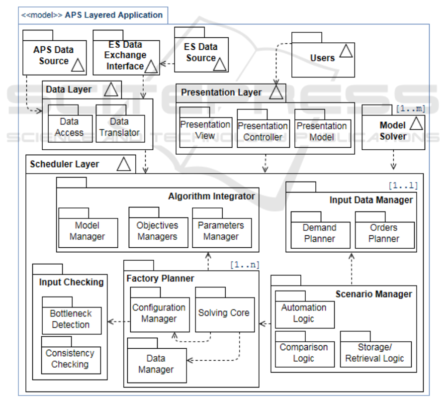
4.2 Development View
This view focuses on the actual modules
organization, at the software environment, packaged
in sub-systems and components; it helps to allocate
FR and manage the project development (Kruchten,
1995). It shows the organization of modules,
libraries, subsystems, and development units,
mapping software to environment (Northrop, 2003).
4.2.1 Primary Presentation
Using UML, a Component Diagrams (Object
Management Group, 2013) represents the view,
which can denote either logical (e.g. business or
process modules) or physical elements (e.g. COM+
or .NET elements, etc.) (Fakhroutdinov, 2014).
Which type of component is used depends on the
required level of abstraction of the diagram.
The Component Diagram of Fig. 2 represents
logical components, which may have different levels
abstraction. The external actors that interoperate
with the APS have been included as systems.
4.2.2 Element Catalogue
There are three systems that need to interoperate:
MS and ES represent ‘actors’ of the Logical View,
and they are specified in order to show how they
relate. However, since these actors may vary for
each specific SwA, they are also variation points.
The third system represents the APS itself. Both
Presentation and Data Layers are mapped to
subsystems, while the packages from the Scheduler
layer are now subsystems, in order to increase
readability, by avoiding adding more subsystems.
The connections to the ES and MS are made
usually using a TCP/IP protocol, regardless if it is
internet or intranet. While the connection is in the
diagram, its implementation may vary on each case.
It is important to note the match between both
views, because it displays their interrelation and
shows the representation of logic components.
Physical components are outside the scope of a RA
(Behere, et al., 2013), and are not presented.
Developers are the stakeholders for the view, and
thus, components are modular parts with
encapsulated content (Fakhroutdinov, 2014), that are
refined and modelled through the development life
cycle. Since a component may be manifested by
many artefacts, the current level of abstraction is
enough for the RA, leaving enough room to add
particular considerations for each concrete case.
4.2.3 Variability Guide
Since the ‘Model Solver’ represents the actor MS of
the Logic View, it has the same condition than
before, and more than one may exist; then, the
connection/translation with the APS may vary.
The internal components of ES are detailed,
because the existence of the ES-DEI component
depends on the organization. This variation point
can change the interoperation and communication
between with the APS, and must considered.
The subsystem that represents the User Interface
has a higher level of abstraction than in the Logic
View, because at the component level, the inner
components vary with some implementation
decisions (such as programming language, and type
of application -web, standalone, etc.).
Also, following previous decisions, ‘Demand
Planner’ is showcased as an inner component of the
‘Input Data Manager’ subsystem. Still, it can be an
external system, as it is on the Oracle ASCP case.
5 CONCLUSIONS
This paper presents work in progress towards a
Reference Architecture for an APS (APS-RA), based
on Functional Requirements previously elicited
through a study of the literature.
The FR are compared to the main features of
commercial leading suites (SAP APO and Oracle e-
Business ASCP), to validate the proposed
requirements, obtaining a good match between them.
The paper introduces the first two views of the APS-
RA, based on the "4+1" View Model, suggested by
ICEIS 2016 - 18th International Conference on Enterprise Information Systems
438
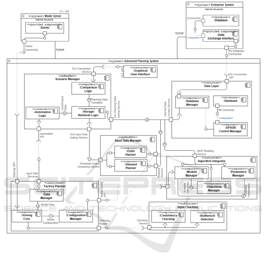
Figure 2: Component Diagram for the Development View of the APS Reference Architecture.
the standard ISO/IEC 42010:2011 for SwA, and is
represented using UML 2.x diagrams. Only two
views are introduced due to space limitations.
This work offers the beginning of a framework to
support the implementation, helping to define and
clarify the functionality of each component. It adheres
to standardized SE methods, without adding load to
the development process. This increases the quality of
the development, providing the essential base for a
clean design with intrinsic relations between FR, QA
and the RA. It allows the project team to efficiently
and effectively asses the quality and extensiveness of
existing systems, guiding the modification and
adaptation of existing systems to new developments.
Several lines for future works exist, besides
completing the remaining views of the RA. The first
of them is using the Quality Attributes that were
previously elicited along with the FR to generate QA
Scenarios and supplement them with metrics and
indicators based on the international standard series
ISO/IEC 2500n "Quality Management Series". With
these, there is a third future work: evaluate the
commitment of the APS-RA with those QA, by
applying a Software Evaluation method, such as
ATAM (Architecture Trade-off Analysis Method).
A Final future work is to create a specific
implementation of a study case, applying real-case
data, and using the elements generated throughout
this works (FR, QA, and the APS-RA).
REFERENCES
Angelov, S., Grefen, P. & Greefhorst, D., 2012. A
Towards a Reference Architecture for Advanced Planning Systems
439

framework for analysis and design of software
reference architectures. Information and Software
Technology, 54(4), pp. 417-431.
Angelov, S., Trienekens, J. J. M. & Grefen, P., 2008.
Towards a Method for the Evaluation of Reference
Architectures: Experiences from a Case. Paphos,
Cyprus, Springer Berlin Heidelberg, pp. 225-240.
Aslan, B., Stevenson, M. & Hendry, L., 2012. Enterprise
Resource Planning systems: An assessment of
applicability to Make-To-Order companies.
Computers in Industry, 63(7), pp. 692-705.
Bachmann, F. et al., 2003. Chapter 9. Documenting
Software Architectures. In: Software Architecture in
Practice. 2nd ed. Boston, MA: Addison-Wesley.
Behere, S., Törngren, M. & Chen, D.-J., 2013. A reference
architecture for cooperative driving. Journal of
Systems Architecture, 59(10), pp. 1095-1112.
BKCASE Editorial Board, 2014. The Guide to the Systems
Engineering Body of Knowledge (SEBoK). 1.3 ed.
Hoboken, NJ: The Trustees of the Stevens Institute of
Technology.
Clements, P. et al., 2010. Chapter 9. Beyond the Basics..
In: Documenting Software Architectures. Views and
Beyond.. Second Edition ed. s.l.:Addison-Wesley, pp.
217-260.
Davenport, T. & Brooks, J., 2004. Enterprise Systems and
the Supply Chain. Journal of Enterprise Information
Management, 17(1), pp. 8 - 19.
Fakhroutdinov, K., 2014. UML 2.x Diagrams. [Online]
[Accessed 2015] Available at: http://www.uml-
diagrams.org/component-diagrams.html.
Fleischmann, B. & Koberstein, A., 2015. Chapter 6.
Strategic Network Design. In: H. Stadtler, C. Kilger &
H. Meyr, eds. Supply Chain Management and
Advanced Planning. Germany: Springer Berlin
Heidelberg, pp. 107-123.
Framinan, J. & Ruiz, R., 2010. Architecture of
manufacturing scheduling systems: Literature review
and an integrated proposal. European Journal of
Operational Research, 205(2), pp. 237-246.
Henning, G., 2009. Production Scheduling in the Process
Industries: Current Trends, Emerging Challenges and
Opportunities. Computer Aided Chemical
Engineering, Volume 27, pp. 23-28.
Hvolby, H.-H. & Steger-Jensen, K., 2010. Technical and
industrial issues of Advanced Planning and
Scheduling (APS) systems. Computers in Industry,
61(9), pp. 845-851.
ISO/IEC/IEEE, 2011. 42010:2011 - ISO/IEC/IEEE
Systems and software engineering -- Architecture
description. s.l.:IEEE Computer Society.
Kallestrup, K. B., Lynge, L. H., Akkerman, R. &
Oddsdottir, T. A., 2014. Decision support in
hierarchical planning systems: The case of
procurement planning in oil refining industries.
Decision Support Systems.
Kontio, M., 2008. Architectural manifesto: Adopting agile
development, Part 5, s.l.: s.n.
Kruchten, P., 1995. The 4+1 View Model of Architecture.
IEEE Software, 12(6), pp. 42-50.
Lothka, R., 2005. Should all apps be n-tier?. [Online]
[Accessed 12 2014] Available at:
http://lhotka.net/weblog/ShouldAllAppsBeNtier.aspx.
Microsoft Patterns & Practices Team, 2009. Microsoft®
Application Architecture Guide (Patterns &
Practices). 2nd ed. s.l.:O'Reilly.
Nguyen, D. et al., 2011. A Methodology for Developing
an Agent Systems Reference Architecture. In: Agent-
Oriented Software Engineering XI. s.l.:Springer Berlin
Heidelberg, pp. 177-188.
Norta, A., Grefen, P. & Narendra, N. C., 2014. A
reference architecture for managing dynamic inter-
organizational business processes. Data & Knowledge
Engineering, May, Volume 91, pp. 52-89.
Northrop, L., 2003. Chapter 2. What Is Software
Architecture?. In: Software Architecture in Practice.
2nd ed. Boston, MA: Addison-Wesley.
Object Management Group, 2013. OMG Unified Modeling
Language TM (OMG UML). 2.5 ed. s.l.:OMG.
Oracle, 2015. [Online] [Accessed 2015] Available at:
http://www.oracle.com/us/products/applications/ebusi
ness/scm/051323.html.
Pääkkönen, P. & Pakkala, D., 2015. Reference
Architecture and Classification of Technologies,
Products and Services for Big Data Systems. Big Data
Research, February, 2(4), pp. 166-186.
Stadtler, H., 2005. Supply chain management and
advanced planning––basics, overview and challenges.
European Journal of Operational Research, 163(3),
pp. 575-588.
Stadtler, H., 2015. Supply Chain Management: An
Overview. In: H. Stadtler, C. Kilger & H. Meyr, eds.
Supply Chain Management and Advanced Planning.
5th ed. University of Hohenheim: Springer Berlin
Heidelberg, pp. 3-28.
Stadtler, H. et al., 2012. Advanced Planning in Supply
Chains. Illustrating the Concepts Using an SAP®
APO Case Study. First Edition ed. Berlin: Springer-
Verlag Berlin Heidelberg.
Vidoni, M. & Vecchietti, A., 2015. A systemic approach
to define and characterize Advanced Planning Systems
(APS). Computers & Industrial Engineering, Volume
90, pp. 326-338.
Yonghua Zhou, Yuliu Chen & Huapu Lu, 2004. UML-
based systems integration modeling technique for the
design and development of intelligent transportation
management system. s.l., IEEE, pp. 6061-6066.
Zoryk-Schalla, A. J., Fransoo, J. C. & de Kok, T. G.,
2004. Modeling the planning process in advanced
planning systems. Information & Management, 42(1),
pp. 75-87.
ICEIS 2016 - 18th International Conference on Enterprise Information Systems
440
