
Breaking the Boundaries of Meta Models and
Preventing Information Loss in Model-Driven Software Product Lines
Thomas Buchmann and Felix Schw
¨
agerl
Chair of Applied Computer Science I, University of Bayreuth, Universit
¨
atsstrasse 30, 95440 Bayreuth, Germany
Keywords:
Software Product Lines, Model-Driven Development, Unconstrained Variability, Information Loss, Negative
Variability, Application Engineering.
Abstract:
Model-driven software product line engineering is an integrating discipline for which tool support has be-
come available recently. However, existing tools are still immature and have several weaknesses. Among
others, limitations in variability, caused by meta model restrictions, and unintended information loss are not
addressed. In this paper, we present two conceptual extensions to model-driven product line engineering
based on negative variability, being alternative mappings and surrogates. Alternative mappings allow for un-
constrained variability, mitigating meta model restrictions by virtually extending the underlying multi-variant
domain model. Surrogates prevent unintended information loss during product derivation based on a context-
sensitive product analysis, which can be controlled by a declarative OCL-based language. Both extensions
have been implemented in FAMILE, a model-driven product line tool that is based on EMF, provides dedi-
cated consistency repair mechanisms, and completely automates application engineering. The added value of
alternative mappings and surrogates is demonstrated by a running example.
1 INTRODUCTION
Software engineering aims at increasing the produc-
tivity of software engineers by providing powerful
methods and tools for software development. Among
others, model-driven software engineering and soft-
ware product line engineering have emerged as com-
plementary disciplines contributing to the achieve-
ment of this goal.
Model-Driven Software Engineering (MDSE)
(Frankel, 2003; V
¨
olter et al., 2006) puts strong em-
phasis on the development of high-level models rather
than on the source code. Models are not considered as
documentation or as informal guidelines how to pro-
gram the actual system. In contrast, models have a
well-defined syntax and semantics. Moreover, model-
driven software engineering aims at the development
of executable models. Ideally, software engineers op-
erate only on the level of models such that there is no
need to inspect or edit the actual source code (if any).
Software Product Line Engineering (SPLE)
(Clements and Northrop, 2001; Pohl et al., 2005;
Weiss and Lai, 1999) deals with the systematic de-
velopment of products belonging to a common sys-
tem family. Rather than developing each instance of a
product line from scratch, reusable software artefacts
are created such that each product may be composed
from a library of components. Basically, two different
approaches exist to realize variability in SPLE: (1) In
approaches based upon positive variability, product-
specific artefacts are built around a common core.
Composition techniques are used to derive the final
products. (2) In approaches based on negative vari-
ability, a superimposition of all variants is created
in the form of a multi-variant domain model. The
derivation of products is achieved by removing all
fragments of artefacts implementing features not be-
ing contained in the specific feature configuration for
the desired product.
In the past, several approaches have been taken
in combining both techniques to get the best out of
both worlds, resulting in the integrating discipline
Model-Driven Product Line Engineering (MDPLE).
Both software engineering techniques consider mod-
els as primary artefacts: Feature models (Kang et al.,
1990) are used in product line engineering to cap-
ture the commonalities and differences of a prod-
uct line, whereas Unified Modeling Language (UML)
(OMG, 2015) models or domain-specific models are
used in model-driven software engineering to de-
scribe the software system at a higher level of ab-
straction. The Eclipse Modeling Framework (EMF)
Buchmann, T. and Schwägerl, F.
Breaking the Boundaries of Meta Models and Preventing Information Loss in Model-Driven Software Product Lines.
In Proceedings of the 11th International Conference on Evaluation of Novel Software Approaches to Software Engineering (ENASE 2016), pages 73-83
ISBN: 978-989-758-189-2
Copyright
c
2016 by SCITEPRESS – Science and Technology Publications, Lda. All rights reserved
73
(Steinberg et al., 2009) has been established as an ex-
tensible platform for the development of MDSE ap-
plications. It is based on the Ecore meta model which
is compatible with the OMG Meta Object Facility
(MOF) specification (OMG, 2011).
In this paper, we address two issues which have
been neglected so far in MDPLE research, being
limitations in variability and unintended information
loss. We have identified these problems (among oth-
ers) from a large case study (Buchmann et al., 2012)
which had been performed using our old tool chain for
model-driven product line engineering (Buchmann
and Westfechtel, 2014). Furthermore, a comparison
of tools available in literature has been taken into
account (see Related Work in Section 5). To over-
come the identified issues, we provide the contri-
butions alternative mappings and surrogates, which
have been implemented as extensions to the MDPLE
tool FAMILE (Buchmann and Schw
¨
agerl, 2012a;
Buchmann and Schw
¨
agerl, 2012b; Buchmann and
Schw
¨
agerl, 2015a). The addressed issues and the pre-
sented solutions are summarized below.
Issue: Limitations in Variability. Since approaches
which rely on negative variability use a multi-
variant domain model, the respective meta model
is a limiting factor for variability. In particular,
single-valued structural features can only hold one
value, e.g., a UML class may only have one name.
Furthermore, each model element may have ex-
actly one container.
Contribution: Alternative Mappings. The concept
of alternative mappings allows for variability in
values of single-valued features of domain model
elements (e.g. UML class names). This is realized
by virtual extensions to the multi-variant domain
model, which are physically located in the map-
ping model.
Issue: Unintended Information Loss. When prod-
ucts are derived from the multi-variant domain
model, context-sensitive information that is
stored within cross-references, e.g. a transitive
inheritance relationship, may get lost; state-of-
the-art tools only take context-free information
into account when deriving products.
Contribution: Surrogates. Unintended information
loss is addressed by means of surrogate rules,
which can be defined in a declarative way using
the OCL-based language SDIRL. During product
derivation, these rules are interpreted; to prevent
information loss, reference targets are replaced by
appropriate substitutes.
The paper is structured as follows: In Section 2,
we align the MDPLE tool FAMILE with existing
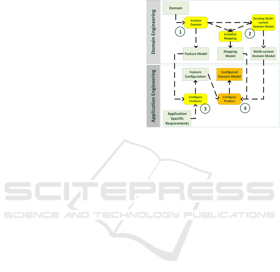
Figure 1: Model-driven product line engineering process as
supported with FAMILE.
SPLE development processes. Section 3 describes
FAMILE in general, before the new contributions are
explained in detail in Section 4. Section 5 discusses
related work, before the paper is concluded.
2 MODEL-DRIVEN PRODUCT
LINE ENGINEERING
The contributions presented in this paper are embed-
ded into a model-driven product line engineering pro-
cess as shown in Figure 1. Typically, product line
engineering distinguishes between domain and ap-
plication engineering (Clements and Northrop, 2001;
Pohl et al., 2005). Domain engineering is dedicated
to analyzing the domain and capturing the results in
a model which describes commonalities and differ-
ences thereof. Furthermore, an implementation – the
so called platform – is provided at the end of domain
engineering. The platform is then used during appli-
cation engineering to derive application specific prod-
ucts, i.e., instances of the product line.
In our approach, domain and application engineer-
ing differ from each other also with respect to re-
quired processes: Domain engineering requires a full-
fledged development process, while application engi-
neering is reduced to a simple configuration process,
which is realized in a preferably automated way. The
activities belonging to the entire engineering process
are described below:
1. Analyze Domain. A feature model describing
mandatory, optional and alternative features
ENASE 2016 - 11th International Conference on Evaluation of Novel Software Approaches to Software Engineering
74

within the product line captures the result of the
domain analysis. Typically, Feature-Oriented Do-
main Analysis (FODA) (Kang et al., 1990) or one
of its descendants – like FORM (Kang et al.,
1998) – is used to analyze the domain.
2. Develop Configurable Domain Model.Afterwards,
a multi-variant domain model is developed, which
realizes all features determined in the previous
step. A link (mapping model) between the feature
model and the domain model is established,
e.g., by annotating model elements with feature
expressions.
3. Configure Features. In order to build a specific
system with the reusable assets provided by the
product line, features of the feature model have
to be selected. The selected features constitute a
feature configuration, describing the characteris-
tics of the product configuration to be derived.
4. Configure Domain Model. According to the se-
lection of features made in the previous step, the
domain model is configured automatically. This
is done by selecting all domain model elements
which are not excluded by feature expressions
evaluating to false. The result of this step is an
application-specific configured domain model.
Please note that the activity Develop Multi-variant
Domain Model comprises the phases Domain Re-
quirements Engineering, Domain Design, Domain
Implementation and Domain Testing, as described
in the product line process proposed by Pohl et al.
(Pohl et al., 2005). In a model-driven software en-
gineering process, the corresponding artefacts pro-
duces by these subprocesses are represented as mod-
els. FAMILE is able to handle the respective models
as long as their meta models are based upon Ecore.
3 THE TOOL FAMILE
Before we give detailed descriptions of the new con-
cepts alternative mappings and surrogates, let us
briefly provide a short description of our tool FAMILE
by detailing its architecture and existing consistency
mechanisms. More comprehensive tool descriptions
can be found in (Buchmann and Schw
¨
agerl, 2012a;
Buchmann and Schw
¨
agerl, 2012b; Buchmann and
Schw
¨
agerl, 2015a).
3.1 Architecture
FAMILE (Features and Models in Lucid Evolution) is
an EMF-based MDPLE tool chain that offers capa-
bilities to capture commonalities and variabilities of
a software family using feature models and to map
features to elements of arbitrary EMF-based domain
models, which contain the realization of those fea-
tures. FAMILE has been developed itself in a model-
driven way, being based on several meta models. The
feature meta model describes the structure of feature
model and feature configurations, respectively, and
F2DMM (Feature to Domain Mapping Model) is the
meta model for mappings between features and re-
alization artefacts (elements of the multi-variant do-
main model).
Figure 2 shows the (meta) models involved in our
tool chain. A feature model (Batory, 2005) consists of
a tree of features. A non-leaf feature may be decom-
posed in two ways. In the case of an AND decom-
position, all of its child features have to be selected
when the parent is selected. In contrast, for an OR
decomposition exactly one child has to be selected.
In addition, our feature modeling tool complies with
cardinality-based feature modeling (Czarnecki et al.,
2005). EMF Validation is used to check correspond-
ing feature configurations against pre-defined consis-
tency constraints (Heidenreich, 2009).
FAMILE’s core component is an editor for map-
ping models (F2DMM), which is used to interconnect
the feature model and the Ecore-based domain model.
To this end, a mapping model consists of a tree of
three different kinds of mappings, which are created
by the tool transparently to reflect the tree structure of
the mapped domain model:
Object Mappings refer to an existing EObject from
the multi-variant domain model and reflect its
tree structure using the Composite design pattern
(Gamma et al., 1994).
Attribute Mappings refer to the string representa-
tion of a concrete value of an attribute of a mapped
object.
Cross-reference Mappings represent the applied
occurrence of an object that is already mapped by
an object mapping.
The connection between domain and feature
model is realized by feature expressions specified
with FAMILE’s Feature Expression Language (FEL).
A feature expression may be assigned to each kind
of mapping and consists of a propositional logical ex-
pression on the variables defined in the feature model.
Once a valid feature configuration is provided,
FAMILE may be used to derive the configured
domain model by filtering all domain model ele-
ments decorated with feature expressions evaluating
to false. During product derivation, repair actions are
applied to ensure well-formedness (Buchmann and
Schw
¨
agerl, 2012a). To this end, context-free consis-
Breaking the Boundaries of Meta Models and Preventing Information Loss in Model-Driven Software Product Lines
75
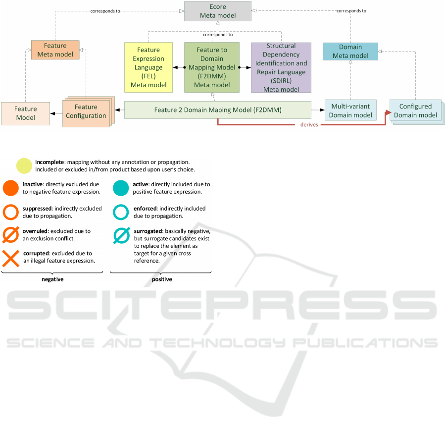
Figure 2: Architectural overview of FAMILE.
Figure 3: Possible selection states for F2DMM mappings
and their graphical representation.
tency constraints are automatically derived from the
used domain meta model. Furthermore, the SPL en-
gineer may specify context-sensitive constraints using
the textual language SDIRL (Structural Dependency
Identification and Repair Language).
3.2 Selection States
The evaluation of a feature expression with respect
to a given feature configuration results in a selection
state. Thus, selection states determine the presence
of a mapped object, cross-reference, or attribute value
in the product described by a specific feature config-
uration. They may also indicate that automatic repair
actions have been applied to ensure well-formedness
or that a surrogate rule has been applied to prevent
information loss (see Sections 3.3 and 4.1). Figure 3
depicts all eight selection states that may be assigned
to a mapping in F2DMM.
Four selection states immediately result from eval-
uating a mapping’s assigned feature expression: ac-
tive and inactive denote that it evaluates to a posi-
tive or negative value, corrupted means that there are
syntax errors in the expression. The state incomplete
arises in case a mapping has no feature expression as-
signed or as long as no feature configuration has been
loaded. The four remaining selection states are moti-
vated and explained below.
3.3 Propagation Strategies
When applying a feature configuration to the mapping
model and calculating the respective selection states,
selection states contradicting context-free or context-
sensitive consistency constraints in the respective do-
main meta model may arise. A so called dependency
conflict is present if a mapped element is active while
a dependent element, e.g., its container, is inactive.
Propagation strategies have been introduced as an
automatic consistency repair mechanism to resolve
dependency conflicts (Buchmann and Schw
¨
agerl,
2012a). The SPL engineer may choose among two
pre-defined strategies, being forward and reverse
propagation. The application of propagation strate-
gies may lead to two new selection states: Either,
an inactive mapping can be artificially made positive,
i.e. enforced, or an active mapping can be artificially
made negative, i.e. suppressed. In order to indicate
the application of a propagation strategy to the user,
different symbols (empty circles instead of filled cir-
cles) are used for their representation (cf. Figure 3).
4 EXTENSIONS CONTRIBUTED
TO FAMILE
In this section, the core contributions of this paper,
surrogates and alternative mappings are explained.
After motivating the respective issues, the general so-
lutions are presented and then demonstrated by exam-
ples referring to the domain of Home Automation Sys-
tems (HAS), a prominent example in SPL literature,
e.g., (Pohl et al., 2005). HAS provide a communica-
tion and controlling platform for home devices such
as ovens, shutters, etc. Depending on the customers’
ENASE 2016 - 11th International Conference on Evaluation of Novel Software Approaches to Software Engineering
76
hardware specifications and the desired degree of au-
tomation, a variety of products may be derived from
the product line.
4.1 Surrogates
The derivation of configured domain models in ap-
proaches based on negative variability consists in fil-
tering of elements being mapped to a feature ex-
pression that evaluates to a negative selection state.
Filtering cross-references, however, may result in
unintended information loss, especially concerning
context-sensitive information that is encoded transi-
tively by a sequence of references. Let’s take gener-
alizations in a UML model as an example: Within the
UML specification (OMG, 2015), a generalization is
defined as a directed relationship which is owned by
the more specific class. The general class, however,
is referenced by means of a directed non-containment
reference. As a consequence, filtering a superclass re-
sults in a dangling edge. Completely discarding the
generalization results in information loss: Given the
fact that the filtered class was part of an inheritance hi-
erarchy, the user might want to replace the filtered ref-
erenced class with its closest non-filtered superclass,
for example.
4.1.1 Surrogate Rules
To address issues like these, we have extended the lan-
guage SDIRL by surrogate rules. Generally, SDIRL
allows to phrase a set of dependency rules referring to
the meta model(s) of the multi-variant domain model.
A dependency rule states that an element, referred to
by its class, has a context sensitive dependency to a
set of elements described by an OCL expression in
the requires part. For instance, the dependency rule in
Listing 1 defines that a UML Generalization depends
on the referenced general class.
Using the surrogates extension, a dependency rule
may include an arbitrary number of surrogate state-
ments, where OCL expressions that must conform to
the type of the requires variable can be phrased. The
expression may refer to the objects bound to the ele-
ment and requires variables. Objects that result from
evaluating any of the attached surrogate expressions
are recorded as surrogate candidates for the given
cross-reference. Surrogate candidates may replace
the element(s) bound to the requires variable as cross-
reference target(s). In our generalization example (see
Listing 1), these are all superclasses of the required
class (returned after evaluating cls.allParents()).
Listing 1: SDIRL rule for generalizations.
dependency G e n e r a l i z a t i o n T a r g e t {
el e m e n t gen : uml . G e n e r a l i z a t i o n
r e q u i r e s c l s : uml . C l a s s i f i e r = {
gen . g e n e r a l
}
s u r r o g a t e {
c l s . a l l P a r e n t s ( )
}
}
4.1.2 Rule Application
Both dependency and surrogate rules are pre-
calculated during domain engineering. In Subsec-
tion 3.2, the selection state surrogated has been intro-
duced for cross-reference mappings being basically
inactive or suppressed, but for which at least one sur-
rogate candidate having a positive selection state ex-
ists. A surrogate rule can revoke the effect of a previ-
ously applied propagation strategy (see Section 3.3).
During product derivation, one of the determined
surrogate candidates must be chosen by the user to
replace the applied occurrence of the mapped object.
FAMILE supports three different methods for choos-
ing one of the matching surrogate candidates: In a
fully automatic mode, the first surrogate candidate is
selected whereas in an interactive mode the user can
select among the set of all candidates. Furthermore,
the user can choose not to use surrogates at all. In this
case, the information loss is intentionally ignored.
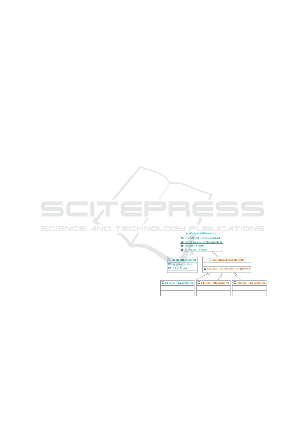
Figure 4: UML2 class diagram showing the realization of
wireless connections in the multi-variant domain model.
4.1.3 Example
The class diagram in Figure 4 shows the realization of
remote connections for wireless connections between
HAS components, including Bluetooth. It comprises
a three-layered inheritance hierarchy. The four con-
crete connector classes each correspond to one fea-
ture. Figure 5 shows the initial mapping of the pack-
age wifi in our running example.
Breaking the Boundaries of Meta Models and Preventing Information Loss in Model-Driven Software Product Lines
77
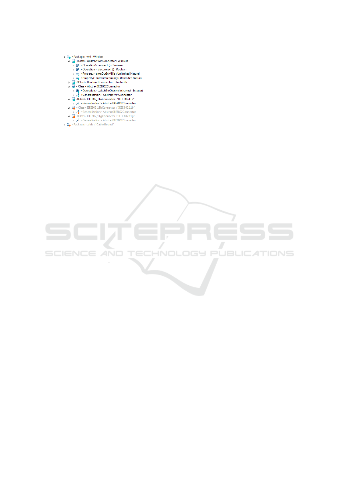
Figure 5: Initial mapping for the inheritance hierarchy.
Surrogates come into play as soon as elements
with a negative selection state are cross-referenced by
another, positively annotated, element. We simulate
such a situation by assigning the feature expression
false to the class AbstractIEEE802Connector (see Fig-
ure 6). Due to the SDIRL rule GeneralizationTarget
defined in Listing 1, the generalization owned by
IEEE802 11aConnector requires the class Abstract-
IEEEConnector. For the target of the reference gen-
eral, a surrogate candidate has been pre-calculated by
evaluating the surrogate statement within the SDIRL
rule: the class AbstractWifiConnector, which is lo-
cated at the top of the inheritance hierarchy. As a
consequence, the selection state of the reference be-
comes surrogated.
The result of the surrogate rule application is de-
picted in Figure 7. The class AbstractIEEEConnec-
tor has been excluded from the product. The gener-
alization owned by IEEE802
11aConnector has been
re-targeted to AbstractWifiConnector. This way, tran-
sitive inheritance information has been maintained.
4.2 Alternative Mappings
In our approach based on negative variability, a multi-
variant domain model constitutes the superimposition
of all products. Nevertheless, it is an ordinary model
instance which must satisfy the structural constraints
imposed by its meta model. Unfortunately, there are
at least two structural constraints which impede the
use of a standard EMF model instance as the multi-
variant domain model without being affected by the
issue of limitations in variability (see introduction):
Value Variability. EMF distinguishes between
single-valued structural features with an upper
bound of 1 and multi-valued structural features
with an upper bound greater than 1 or −1 (un-
bounded multiplicity). In a valid EMF instance,
at most one value may exist for a single-valued
structural feature, and the multi-variant domain
model cannot intrinsically represent alternative
feature values for different product variants.
Container Variability. In EMF, an object must either
be the root of a resource, or be contained by ex-
actly one container object. Thus, the location of
an object in the containment tree must be fixed
in the multi-variant domain model. This restric-
tion prevents different FAMILE products from
containing a specific object at different locations
without creating redundant copies of objects.
4.2.1 Definition of Alternative Mappings
The FAMILE extension alternative mappings miti-
gates the restrictions described above. Alternative
mappings are supplementary domain model elements
defined in the mapping model that may be virtually
inserted into the configured domain model at arbi-
trary locations. For each of the three kinds of map-
pings (see Section 3.1), FAMILE introduces differ-
ent possibilities to specify alternative mappings in the
F2DMM editor. These will not influence the multi-
variant domain model, but refer to the mapping model
only (and of course, affect derived products).
Alternative Object Mappings allow to virtually ex-
tend the multi-variant domain model with (sub-
trees of) objects. FAMILE provides two possibil-
ities: Either, the root of the inserted fragment is
located in a separate EMF resource, or objects are
defined in-place in the mapping model.
Alternative Cross-reference Mappings allow for the
modification of applied occurrences of objects in
configured domain models. F2DMM supports in-
ternal as well as external cross-reference map-
pings, which refer either to an existing, mapped
element inside the F2DMM model, or to an ordi-
nary EMF object in a different, non-mapped EMF
resource.
Alternative Attribute Mappings. Besides references,
the state of an EMF object is encoded in the val-
ues of its attributes. For a given (single- or multi-
valued) attribute of a mapped object, an additional
value may be specified by means of the string
representation which is defined by the respective
EDataType. The string is converted into its ob-
ject representation as soon as product derivation
includes the alternative attribute due to a positive
selection state.
4.2.2 Mutex Conflicts and Selection Strategies
The introduction of alternative mappings leads to
more flexible mapping models: For single-valued fea-
tures, several values may be defined. As soon as a
ENASE 2016 - 11th International Conference on Evaluation of Novel Software Approaches to Software Engineering
78
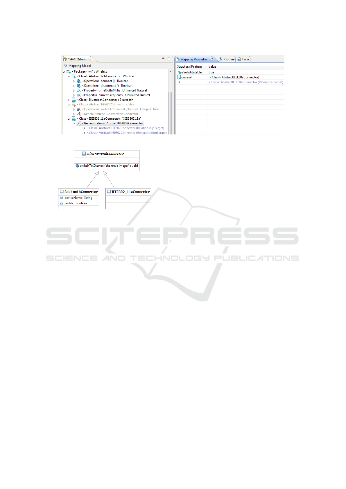
Figure 6: The disconnected inheritance hierarchy is repaired by means of a surrogate rule defined in SDIRL.
Figure 7: Result after product derivation, including surro-
gate selection, in class diagram representation.
configured domain model is derived from a mapping
with multiple values competing for a single-valued
feature, the result is not guaranteed to be unique as
the values are mutually exclusive. In analogy to de-
pendency conflicts (cf. Section 3.3), a mutex con-
flict occurs between a set of domain model elements
{e
1
, . . . , e
n
} whenever the following conditions hold:
• The mappings of all elements {e
1
, . . . , e
n
} are con-
tained in the same object mapping.
• All elements {e
1
, . . . , e
n
} are values of the same
single-valued structural feature.
• The selection state of more than one element in
{e
1
, . . . , e
n
} is active or enforced.
When applying selection strategies, the following
rules are applied in FAMILE:
1. Since the multi-variant domain model is a valid
EMF instance, there may be at most one non-
alternative mapping involved in a mutex conflict.
If such a mapping exists with a positive selection
state, it is preferred over competing alternative
mappings, i.e. they are all assigned the selection
state overruled if they remained in a positive se-
lection state.
2. If only alternative mappings are involved in a mu-
tex conflict, this is resolved by the order in which
the alternative mappings have been inserted, i.e.
the first alternative with a positive selection state
is preferred. Again, the selection state overruled
is assigned to all other mappings which had a pos-
itive selection state previously.
3. In both cases, the user may override the default
behavior by assigning a suitable feature expres-
sion to the elements that have a higher priority
than the desired candidate element.
4.2.3 Example
We conclude this section by an example that demon-
strates the definition of an alternative attribute map-
ping which causes a mutex conflict, and the resolution
of this conflict. Figure 8 depicts a state diagram de-
scribing the dynamic behavior of microwave ovens in
the HAS product line.
It is intended to rename the transition stopOven
(c.f., Figure 8) to “emergencyStop” in case the fea-
ture “Cooldown Mode” is selected. Due to restric-
tions in the UML meta model (upper bound of 1),
the name of a transition may have at most one value
and we cannot introduce the second name as a part
of the multi-variant domain model. As a replace-
ment, we introduce an alternative attribute mapping
below the transition stopOven, specifying the alter-
native value “emergencyStop” for the structural fea-
ture name. Next, we annotate the alternative mapping
with ”Cooldown Mode”.
As shown in Figure 9, this causes a mutex con-
flict: In the current feature configuration, the fea-
ture “Cooldown Mode” is selected and both names,
“stopOven” and “emergencyStop” basically have a
positive selection state assigned. According to the
selection strategy introduced above, the alternative
value “emergencyStop” is artificially excluded (selec-
tion state overruled).
In addition, the default name “stopOven” shall
only be applied for products which deselect the fea-
ture “Cooldown Mode”. A corresponding feature ex-
Breaking the Boundaries of Meta Models and Preventing Information Loss in Model-Driven Software Product Lines
79
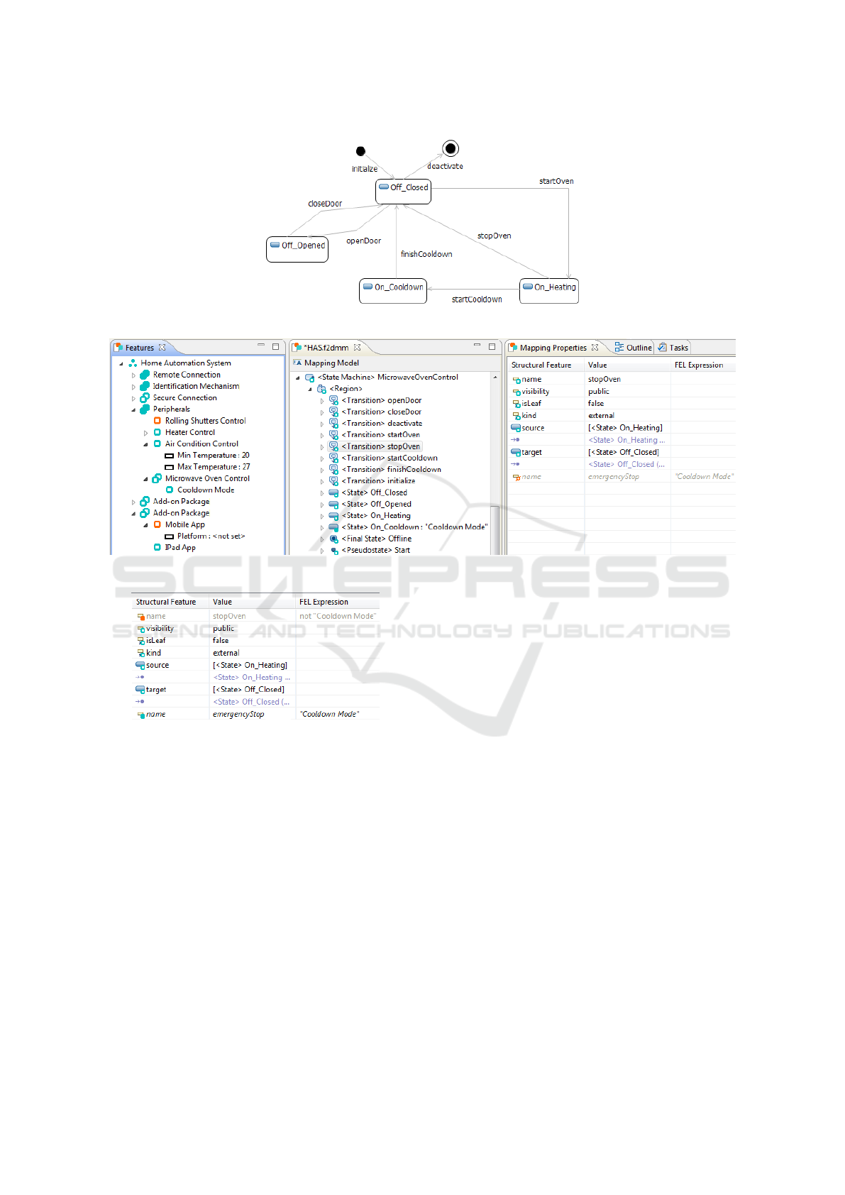
Figure 8: Superimposed statechart realizing feature “Microwave Oven” in concrete graphical syntax.
Figure 9: The alternative attribute mapping for the feature name of the transition stopOven causes a mutex conflict.
Figure 10: The mutex conflict is resolved manually in order
to obtain the desired result.
pression is added to the attribute mapping in Fig-
ure 10: not ”Cooldown Mode”. Due to the mutual
exclusion of the feature expressions attached to both
names, the mutex conflict is now avoided, giving the
priority to the alternative value “emergencyStop”. If
we derived the product using the active feature con-
figuration, the transition stopOven would be renamed
to “emergencyStop”.
5 RELATED WORK
Lots of approaches and corresponding tools referring
to model-driven product line engineering have been
published in the past. In (Buchmann and Schw
¨
agerl,
2012a), a comparison of FAMILE with related work
focused on consistency control is given. The compar-
ison provided in (Buchmann and Schw
¨
agerl, 2015a)
aligns FAMILE with related approaches to hetero-
geneous SPLE approaches. Here, after a general
overview, we compare our contributions alternative
mappings and surrogates to related work.
5.1 General Comparison
MDPLE Approaches based on positive variability re-
quire the use of special development tools in order
to specify implementation fragments and to compose
the variable parts with the common core (Whittle
et al., 2009; Apel et al., 2009). The language VML*
(Zschaler et al., 2010) supports both positive and neg-
ative variability, since every feature is realized by a
sequence of small transformations on the core model.
MATA (Whittle et al., 2009) allows to develop model-
driven product lines based on UML. It relies on pos-
itive variability, which means that around a common
core specified in UML, variant models described in
the MATA language are composed to a product spe-
cific UML model. Graph transformations based on
AGG (Taentzer, 2004), which are used to compose the
common core with the single MATA specifications.
ENASE 2016 - 11th International Conference on Evaluation of Novel Software Approaches to Software Engineering
80

An essential requirement in tools based on nega-
tive variability is the mapping between features and
their corresponding implementation fragments. On
the one hand, the mapping information may be ei-
ther stored within the implementation, e.g. by us-
ing preprocessor directives in source code based ap-
proaches (K
¨
astner et al., 2009), or annotations in
model-based approaches (Ziadi and J
´
ez
´
equel, 2006;
Gomaa, 2004). The tool fmp2rsm
1
combines Feature-
Plugin (Antkiewicz and Czarnecki, 2004) with IBM’s
Rational Software Modeler, a UML-based model-
ing tool using specific UML stereotypes for features.
MODPL (Buchmann and Westfechtel, 2014) also uses
stereotypes to annotate Fujaba
2
models. On the other
hand, the mapping information can be made explicit
by using a distinct mapping model. Like FAMILE,
FeatureMapper (Heidenreich et al., 2008) allows to
add variability information to arbitrary Ecore-based
domain models.
5.2 Approaches Allowing for
Unconstrained Variability
In this paper, we have presented alternative mappings
as a technique to overcome meta model restrictions
in multi-variant models, e.g., the representation of
multiple alternative values for single-valued structural
features. To the best of our knowledge, when con-
sidering negative variability, there exists no approach
in the literature that corresponds to alternative map-
pings described here, which explicitly stores alterna-
tive model elements in separate resources in order to
virtually extend multi-variant domain models.
In approaches based on positive variability (Whit-
tle et al., 2009; Apel et al., 2009; Zschaler et al.,
2010), alternative values may be dynamically added
to the platform using separate transformation specifi-
cations. However, during the product derivation pro-
cess, the order in which the single model transforma-
tions are carried out is crucial, since “the last update
wins”. Thus, a conflict detection and resolution mech-
anisms corresponding to mutex constraints and selec-
tion strategies presented here cannot be realized upon
positive variability.
SuperMod (Schw
¨
agerl et al., 2015) applies a fil-
tered editing approach to MDPLE, realizing the up-
date/modify/commit workflow known from version
control systems. The SPL engineer always operates in
a single-version view of the model, which is persisted
in an extrinsic, multi-variant representation transpar-
ently, allowing for unconstrained variability behind
1
http://gsd.uwaterloo.ca/fmp2rsm
2
http://www.fujaba.de/
the curtains. However, in the local workspace, de-
velopers are intentionally restricted to single-version
editing.
5.3 Approaches to Preventing
Information Loss
Surrogate rules, as discussed in this paper, prevent the
loss of information stored in context-sensitive way,
e.g., in a sequence of cross references. The concept
of surrogate rules, which are used to calculate tar-
get candidates beforehand, one of which is chosen as
replacement reference target during product deriva-
tion, is unique in the field of MDPLE. As a replace-
ment, we outline one representative belonging to ap-
proaches performing context-sensitive analyses after
product derivation.
The source-code based tool CIDE (K
¨
astner et al.,
2009) provides the SPL engineer with a product spe-
cific view on the source code, where all source code
fragments not part of the chosen configuration are
omitted in the source code editor. As opposed to
#ifdef -preprocessors, CIDE abstracts from plain text
files and works on the abstract syntax tree of the target
language instead. The tool is based on a product-line
aware type system which helps to detect typing er-
rors resulting from applying negative variability to the
multi-variant model. Since a general type system for
arbitrary languages is still subject to research, a gen-
eral solution is missing. Thus, for each language, a
new grammar and a new product-line aware type sys-
tem must be supplied by the SPL engineer. Further-
more, detected errors are not repaired automatically,
which is in contrast to FAMILE.
6 CONCLUSION
In this paper, we have addressed two issues in SPLE
tooling having been neglected in the past, namely lim-
itations in domain model variability and unintended
information loss.
Our contributions assume negative variability,
where a multi-variant domain model is annotated with
feature expressions. Products may be derived by con-
figuring the feature model and by applying the con-
figuration to the mapping. As a result, all elements
which are annotated with feature expressions evaluat-
ing to false are filtered from the resulting configured
domain model. However, filtering can easily result
in syntactically ill-formed target models. Since the
multi-variant domain model must be instance of the
domain meta model, variability is constrained.
Breaking the Boundaries of Meta Models and Preventing Information Loss in Model-Driven Software Product Lines
81
To address these issues, the following contribu-
tions have been presented in this paper as extensions
to the MDPLE tool FAMILE:
Alternative Mappings. Since the multi-variant do-
main model has to be a valid instance of the do-
main meta model, several constraints must hold.
In particular, single-valued features may contain
at most one value. Thus, it is not possible to ex-
press variability for those features directly. This
restriction is mitigated by our concept of alterna-
tive mappings. These in turn may cause several
values competing for a single-valued feature. To
resolve this, we have realized the detection of mu-
tex conflicts as well as their resolution by means
of selection strategies.
Surrogates. In case an element is filtered, it can-
not occur as the target of another cross-reference.
This way, context-sensitive information may get
lost. Using the mechanism of surrogates, it is pos-
sible to filtered reference targets non-filtered tar-
gets of the same type. Corresponding replacement
rules may be specified declaratively in SDIRL.
Future research addresses evolution of software
product line artefacts, round-trip between domain
and application engineering, and improved support
for maintaining the consistency between model and
generated source code (Buchmann and Schw
¨
agerl,
2015b) in both domain and application engineering.
RESOURCES
The tool FAMILE, including the extensions presented
in this paper, may be obtained by using the Eclipse
update site provided at:
3
We recommend a clean Eclipse Modeling installation.
Screencasts demonstrating the usage of the tool can
be found here:
4
ACKNOWLEDGEMENTS
The authors want to thank Bernhard Westfechtel for
his valuable and much appreciated comments on the
draft of this paper.
REFERENCES
Antkiewicz, M. and Czarnecki, K. (2004). FeaturePlugin:
Feature modeling plug-in for Eclipse. In Proceedings
3
http://btn1x4.inf.uni-bayreuth.de/famile/update/
4
http://btn1x4.inf.uni-bayreuth.de/famile/screencasts/
of the 2004 OOPSLA Workshop on Eclipse Technol-
ogy eXchange (eclipse’04), pages 67–72, New York,
NY.
Apel, S., K
¨
astner, C., and Lengauer, C. (2009). Feature-
House: Language-independent, automated software
composition. In Proceedings of the ACM/IEEE Inter-
national Conference on Software Engineering (ICSE),
pages 221–231. IEEE.
Batory, D. S. (2005). Feature models, grammars, and propo-
sitional formulas. In Obbink, J. H. and Pohl, K., ed-
itors, Proceedings of the 9th International Software
Product Line Conference (SPLC’05), volume 3714
of Lecture Notes in Computer Science, pages 7–20,
Rennes, France. Springer Verlag.
Buchmann, T., Dotor, A., and Westfechtel, B.
(2012). Mod2-scm: A model-driven product
line for software configuration management sys-
tems. Information and Software Technology.
http://dx.doi.org/10.1016/j.infsof.2012.07.010.
Buchmann, T. and Schw
¨
agerl, F. (2012a). Ensuring well-
formedness of configured domain models in model-
driven product lines based on negative variability.
In Proceedings of the 4th International Workshop
on Feature-Oriented Software Development, FOSD
2012, pages 37–44, New York, NY, USA. ACM.
Buchmann, T. and Schw
¨
agerl, F. (2012b). FAMILE: tool
support for evolving model-driven product lines. In
St
¨
orrle, H., Botterweck, G., Bourdells, M., Kolovos,
D., Paige, R., Roubtsova, E., Rubin, J., and Tolvanen,
J.-P., editors, Joint Proceedings of co-located Events
at the 8th European Conference on Modelling Foun-
dations and Applications, CEUR WS, pages 59–62,
Building 321, DK-2800 Kongens Lyngby. Technical
University of Denmark (DTU).
Buchmann, T. and Schw
¨
agerl, F. (2015a). Developing het-
erogeneous software product lines with famile — a
model-driven approach. International Journal on Ad-
vances in Software, 8(1 & 2):232 – 246.
Buchmann, T. and Schw
¨
agerl, F. (2015b). On A-posteriori
Integration of Ecore Models and Hand-written Java
Code. In Pascal Lorenz, M. v. S. and Cardoso, J.,
editors, Proceedings of the 10th International Con-
ference on Software Paradigm Trends, pages 95–102.
SCITEPRESS.
Buchmann, T. and Westfechtel, B. (2014). Mapping fea-
ture models onto domain models: ensuring consis-
tency of configured domain models. Software and Sys-
tem Modeling, 13(4):1495–1527.
Clements, P. and Northrop, L. (2001). Software Product
Lines: Practices and Patterns. Boston, MA.
Czarnecki, K., Helsen, S., and Eisenecker, U. W. (2005).
Formalizing cardinality-based feature models and
their specialization. Software Process: Improvement
and Practice, 10(1):7–29.
Frankel, D. S. (2003). Model Driven Architecture: Apply-
ing MDA to Enterprise Computing. Wiley Publishing,
Indianapolis, IN.
Gamma, E., Helm, R., Johnson, R., and Vlissides, J.
(1994). Design Patterns - Elements of Reusable
Object-Oriented Software.
ENASE 2016 - 11th International Conference on Evaluation of Novel Software Approaches to Software Engineering
82

Gomaa, H. (2004). Designing Software Product Lines with
UML: From Use Cases to Pattern-Based Software Ar-
chitectures. Addison-Wesley, Boston, MA.
Heidenreich, F. (2009). Towards systematic ensuring well-
formedness of software product lines. In Proceedings
of the 1st Workshop on Feature-Oriented Software De-
velopment, pages 69–74, Denver, CO, USA. ACM.
Heidenreich, F., Kopcsek, J., and Wende, C. (2008). Fea-
tureMapper: Mapping features to models. In Compan-
ion Proceedings of the 30th International Conference
on Software Engineering (ICSE’08), pages 943–944,
Leipzig, Germany.
Kang, K. C., Cohen, S. G., Hess, J. A., Novak, W. E.,
and Peterson, A. S. (1990). Feature-oriented do-
main analysis (FODA) feasibility study. Technical Re-
port CMU/SEI-90-TR-21, Carnegie-Mellon Univer-
sity, Software Engineering Institute.
Kang, K. C., Kim, S., Lee, J., Kim, K., Kim, G. J., and Shin,
E. (1998). Form: A feature-oriented reuse method
with domain-specific reference architectures. Annals
of Software Engineering, 5:143–168.
K
¨
astner, C., Apel, S., Trujillo, S., Kuhlemann, M., and Ba-
tory, D. S. (2009). Guaranteeing syntactic correctness
for all product line variants: A language-independent
approach. In Oriol, M. and Meyer, B., editors, TOOLS
(47), volume 33 of Lecture Notes in Business Informa-
tion Processing, pages 175–194. Springer.
OMG (2011). Meta Object Facility (MOF) Core. Object
Management Group, Needham, MA, formal/2011-08-
07 edition.
OMG (2015). Unified Modeling Language (UML). Object
Management Group, Needham, MA, formal/15-03-01
edition.
Pohl, K., B
¨
ockle, G., and van der Linden, F. (2005). Soft-
ware Product Line Engineering: Foundations, Prin-
ciples and Techniques. Springer Verlag, Berlin, Ger-
many.
Schw
¨
agerl, F., Buchmann, T., and Westfechtel, B. (2015).
SuperMod - A model-driven tool that combines ver-
sion control and software product line engineering.
In ICSOFT-PT 2015 - Proceedings of the 10th In-
ternational Conference on Software Paradigm Trends,
pages 5–18, Colmar, Alsace, France. SCITEPRESS.
Steinberg, D., Budinsky, F., Paternostro, M., and Merks,
E. (2009). EMF Eclipse Modeling Framework. The
Eclipse Series. Addison-Wesley, Boston, MA, 2nd
edition.
Taentzer, G. (2004). AGG: A Graph Transformation Envi-
ronment for Modeling and Validation of Software. In
Pfaltz, J., Nagl, M., and B
¨
ohlen, B., editors, Applica-
tions of Graph Transformations with Industrial Rel-
evance, volume 3062 of Lecture Notes in Computer
Science, pages 446–453. Springer Berlin / Heidelberg,
Charlottesville, VA, USA.
V
¨
olter, M., Stahl, T., Bettin, J., Haase, A., and Helsen, S.
(2006). Model-Driven Software Development: Tech-
nology, Engineering, Management. John Wiley &
Sons.
Weiss, D. M. and Lai, C. T. R. (1999). Software Product
Line Engineering: A Family-Based Software Devel-
opment Process. Boston, MA.
Whittle, J., Jayaraman, P., Elkhodary, A., Moreira, A.,
and Arajo, J. (2009). MATA: A Unified Approach
for Composing UML Aspect Models Based on Graph
Transformation. In Katz, S., Ossher, H., France, R.,
and Jzquel, J.-M., editors, Transactions on Aspect-
Oriented Software Development VI, volume 5560 of
Lecture Notes in Computer Science, pages 191–237.
Springer Berlin / Heidelberg.
Ziadi, T. and J
´
ez
´
equel, J.-M. (2006). Software Product Line
Engineering with the UML: Deriving Products. In
K
¨
ak
¨
ola, T. and Duenas, J. C., editors, Software Prod-
uct Lines, pages 557–588. Springer Berlin / Heidel-
berg.
Zschaler, S., S
´
anchez, P., Santos, J., Alf
´
erez, M., Rashid,
A., Fuentes, L., Moreira, A., Ara
´
ujo, J., and Kulesza,
U. (2010). VML* - A Family of Languages for Vari-
ability Management in Software Product Lines. In
van den Brand, M., Gaevic, D., and Gray, J., edi-
tors, Software Language Engineering, volume 5969
of Lecture Notes in Computer Science, pages 82–102.
Springer Berlin / Heidelberg, Denver, CO, USA.
Breaking the Boundaries of Meta Models and Preventing Information Loss in Model-Driven Software Product Lines
83
