
CAPLOS
Compressed Air Powered Lateral Obstacle Simulator
Marc Schneider, Markus Sieber and Berthold F
¨
arber
Human Factors Institute, Universitaet der Bundeswehr Muenchen, Werner-Heisenberg-Weg 39, Neubiberg, Germany
Keywords:
CAPLOS, Compressed Air Powered Lateral Obstacle Simulator, Driver Behaviour, Test Track.
Abstract:
The development process of advanced driver assistance systems (ADAS) should include user studies in order to
ensure optimal human-machine-interaction. Relevant active safety test scenarios must be based on appropriate
use-cases, i.e. critical traffic situations. In order to avoid endangering subjects’ physical well-being, test
equipment is required that reliably simulates obstacles with realistic appearance that are also safe to crash. For
cross-traffic scenarios and the examination of lateral driving behavior, existing test equipment, such as driving
simulators, exhibit certain deficits. The authors present a compressed air powered lateral obstacle simulator
(CAPLOS), a low-cost system for the creation of incursion-based critical situations. This paper describes the
setup of CAPLOS and demonstrates its suitability for use in active safety ADAS user studies with exemplary
driving study data.
1 INTRODUCTION
Advanced driver assistance systems (ADAS) that pro-
vide active safety functions reduce the danger posed
by critical situations, e.g. by helping prevent col-
lisions. During an intervention, these systems co-
operate or compete with the driver for control over
the vehicle and thus have high requirements regard-
ing the design of the human-machine-interaction. To
ensure that these requirements are met, the ADAS de-
velopment process must include user studies (Koenig,
2012). For these driving experiments, the critical sit-
uation in which the ADAS is designed to intervene
must be reproduced in a way that appears realistic to
the driver in order to elicit realistic driver behavior.
At the same time, the situation must be reproduced in
a manner that does not expose the test subject and test
equipment to any real danger.
2 STATE OF THE ART
Several different approaches have been put forward to
provide ADAS developers with the possibility to test
systems in early development stages.
One such approach is the use of driving simula-
tors. Being virtual test beds, driving simulators nat-
urally provide the possibility to expose test subjects
to critical traffic scenarios in the absence of any real
physical threat. They suffer, however, from serious
limitations regarding the simulation of prolonged or
intense vehicle dynamics and are therefore unable to
provide fully realistic kinesthetic force feedback for
highly dynamic maneuvers that are usually inherent
to active safety scenarios. While having severaly ad-
vantages, driving simulators are therefore not deemed
appropriate for a conclusive evaluation of driver be-
havior, see e.g. (Schmitt et al., 2006).
Another approach is the use of safe to crash ob-
stacles in field studies. With test subjects driving a
real car, vehicle dynamics need not be simulated and
are fully realistic. The challenges with this approach
are the reliable reproduction of obstacle placement as
well as the realistic appearance of the obstacle. Sev-
eral studies report the use of foam cuboids or balloon
cars, e.g. (Eckert et al., 2011), but do not mention how
the obstacle was reliably placed in the correct position
at the correct time regardless of external influences
such as wind, or which measures were employed for
the obstacle to have the appearance of a solid object
with which a crash must be avoided.
A more elaborate and expensive piece of test
equipment for the use in field studies is EVITA (Hoff-
mann and Winner, 2008), a system designed for use
on a test track in order to investigate critical scenarios
in longitudinal traffic. It consists of a towed dummy
car that can be released and then perform an intense
braking maneuver, creating a critical situation for the
Schneider, M., Sieber, M. and Färber, B.
CAPLOS - Compressed Air Powered Lateral Obstacle Simulator.
In Proceedings of the International Conference on Vehicle Technology and Intelligent Transport Systems (VEHITS 2016), pages 71-78
ISBN: 978-989-758-185-4
Copyright
c
2016 by SCITEPRESS – Science and Technology Publications, Lda. All rights reserved
71
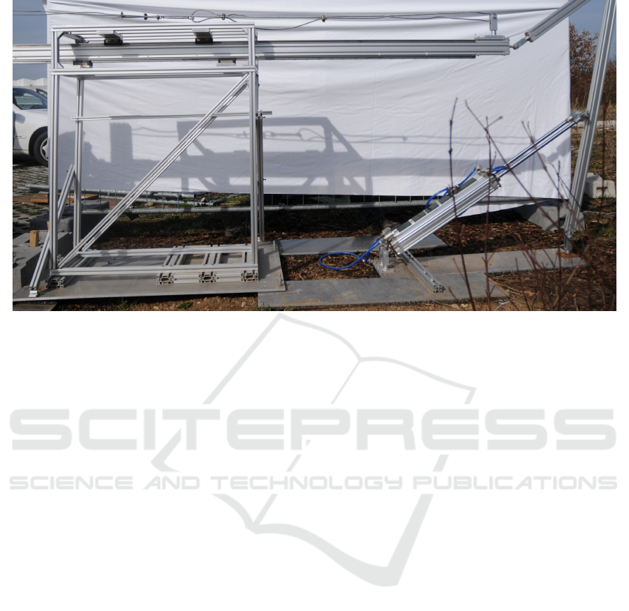
Figure 1: CAPLOS main body.
following car, while being constructed in a way that
cushions a potential collision in order to avoid any
physical harm. EVITA keeps test subjects safe while
simultaneously making a very realistic impression.
Unfortunately, it is not designed for cross-traffic sce-
narios. Test subjects driving behind EVITA are aware
of the possible source of danger in front of them at all
times.
Similarly, other previously existing solutions are
equally expensive designs and/or are based on con-
structions that make test subjects aware of possible
danger, such as rope or cable constructions on or
above the road. The authors desired an easy to con-
struct and inexpensive piece of test equipment for the
use in field studies that can be reliably placed, has re-
alistic appearance while being safe to crash, and can
easily be hidden from sight behind a wide variety of
roadside structures in order to elicit realistic driving
behavior with real vehicle dynamics in cross-traffic
scenarios with unsuspecting drivers.
3 CAPLOS
The authors designed CAPLOS as a low-cost solution
to safely, validly and reliably test realistic driver be-
havior to avoid collisions in cross-traffic scenarios.
3.1 Objectives
CAPLOS was designed as a system to help exam-
ine driver behavior in reaction to suddenly appear-
ing obstacles. The objective was to build a system
that can create a critical situation by making an ob-
stacle appear suddenly, while being low-cost, easy to
set up, easy to hide behind cover or camouflage, that
is safe for drivers and the test vehicle, provides reli-
able obstacle placement, is able to fit different types
of dummy obstacles, makes a realistic impression on
drivers, and provide different triggering options. It
was a requirement that the length of stroke for the
suddenly appearing dummy obstacle be more than 1m
and that there are multiple safety mechanisms: the
system should provide the ability to pull the dummy
obstacle out of harm’s way in the last possible instant,
while the dummy obstacle should also be risklessly
crashable.
3.2 Solution
The proposed solution named CAPLOS (compressed
air powered lateral obstacle simulator, Fig. 1 + 2) con-
sists of 2 pneumatic pistons, a lever-construction, a
pushing rod with fitting bearings, a frame to direct and
stabilize the translation, an air compressor to provide
power, an associated control unit and a mobile and
crashable dummy at the front. A vehicle approaching
and falling below a certain time-to-collision (TTC) to
CAPLOS triggers the system, causing the movement
of the dummy obstacle into the road. In the last in-
stant before a possible collision or in case of electrical
shutdown the pneumatic mechanism automatically re-
tracts the dummy obstacle for safety reasons.
VEHITS 2016 - International Conference on Vehicle Technology and Intelligent Transport Systems
72
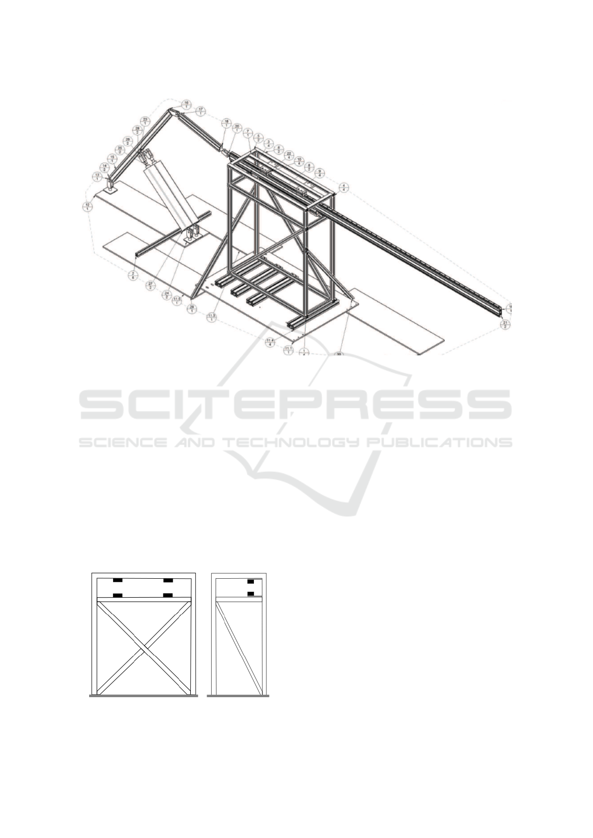
Figure 2: Construction drawing of CAPLOS (Schreiber, 2015).
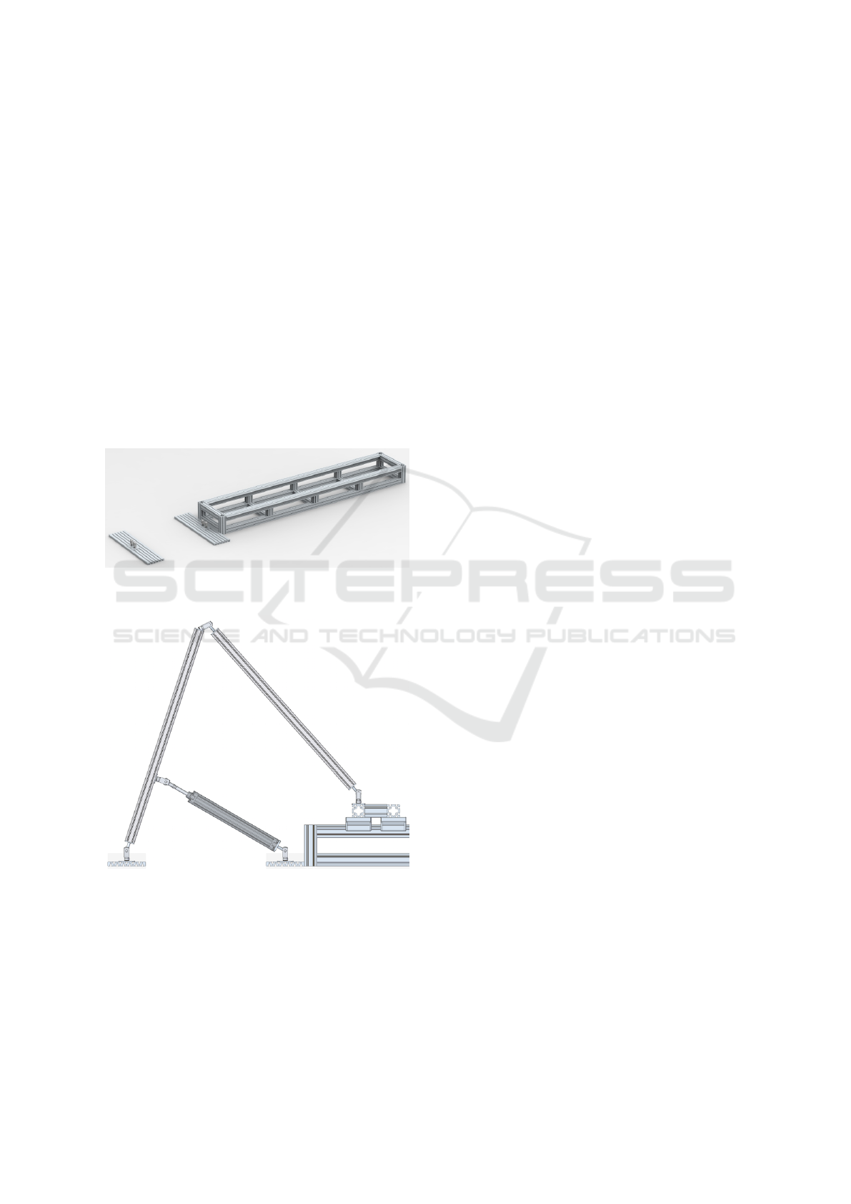
3.3 CAPLOS - Structure
3.3.1 CAPLOS - Frame
The frame (Fig. 3) is connected to a steel base-
plate, which provides stability and weight for the sys-
tem while at the same time it can be separated into
more easily manageable parts for transportation. The
frame itself, built from aluminum profiles, ensures the
straight and controlled translation of the pushing rod
through the exact positioning of the required bearings.
The rigid construction guarantees functionality even
in the hypothetical case of a clamp in the linear move-
ments or the dummy getting hit by a vehicle, ensuring
the safety of test subjects, bystanders, the vehicle and
CAPLOS itself.
Figure 3: Schematic diagram of the CAPLOS frame.
3.3.2 CAPLOS - Power Unit
An off-the-shelf air compressor with 10 bar maxi-
mum pressure is connected to the pistons through
control valves and serves as the power source. In
order to reach the required speed when pushing out
the dummy or pulling it in again, a work-principle
consisting of linear pneumatic pistons was selected.
Through a conversion of the translation’s length and
speed via the lever construction (Fig. 4 + 5) the re-
quired speed dimensions can be reached even with
low-cost pneumatic machinery. The adjustable con-
nection of the pistons to the lever enables mechanical
regulation of length of stroke and movement speed.
This lever construction is connected to the push-
ing rod with a guiding rod. In combination with the
basic frame and rigid implementation of the joints in
the construction, straight friction-reduced movements
are ensured. At the opposite end of the main pushing
rod a dummy of arbitrary dimensions (car silhouette,
pedestrian, ...) can be equipped.
3.3.3 CAPLOS - Control Unit
CAPLOS is controlled by electronic and pneumatic
components built into a case (Fig. 6). In order to
regulate the position of both pneumatic pistons a 5/3-
way-valve (to switch between pushing and pulling)
and a 3/2-way-valve (to convert an electrical trigger
signal to a pneumatic signal) were used in the control
CAPLOS - Compressed Air Powered Lateral Obstacle Simulator
73
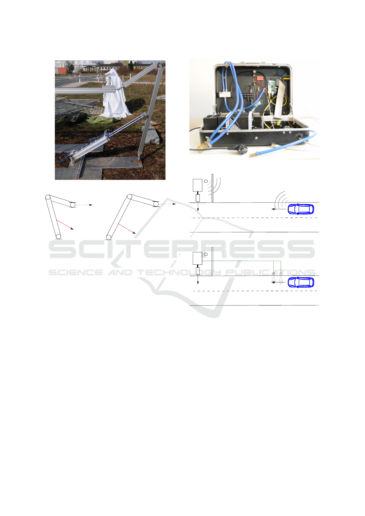
Figure 4: CAPLOS lever construction.
Figure 5: Schematic diagram of the CAPLOS lever con-
struction.
unit of CAPLOS. An electric signal activating the 3/2-
valve causes the 5/3-valve to switch to push out mode.
To switch the state of the 3/2-way-valve a voltage of
12V to 24V is provided by the built-in power supply
unit, which also supplies the additional light barriers.
With the electric signal dropping out, caused either by
CAPLOS receiving the signal to pull back or by the
failing of the electrical power source, CAPLOS auto-
matically returns to pull-in mode by default, thereby
preventing possible harm from system breakdown.
The electrical trigger signal is provided by a Rasp-
berryPi minicomputer’s GPIO-pins or USB-port. The
control unit continually monitors whether the trigger
conditions are met. The required data can be transmit-
ted to the RaspberryPi in several ways, two of which
have so far been implemented for CAPLOS:
• via a WiFi signal sent by the test vehicle (Fig. 7)
• via light barriers and speed-calculation within the
RaspberryPi (Fig. 8)
The system’s activation via WiFi signal is realized
with high-range antennas. The light barriers can be
connected to the RaspberryPi directly with a 5 wire
cable. The experimenter defines the desired trigger
criteria, for example a certain time-to-collision (TTC)
or distance of the ego vehicle to CAPLOS.
Figure 6: Control case of CAPLOS.
Figure 7: Schematic diagram of activation via WiFi.
Figure 8: Schematic diagram of activation via light barriers.
3.3.4 CAPLOS - Dummy
The dummy obstacle, which is positioned at the front
end of CAPLOS’s pushing rod, enables the machine
to carry multiple types of dummies like car silhou-
ettes (Fig. 9) or pedestrian puppets (Fig. 10). In order
to prevent damage to the test vehicle or CAPLOS in
case of the vehicle hitting the dummy, it is comprised
of two distinctive parts linked by hinges, enabling the
obstacle to fold away when hit, thereby significantly
reducing the force on the dummy as well as the test
vehicle. Hook-and-loop fasteners ensure stable cohe-
sion of the dummy parts until a collision occurs.
Guidance of the dummy obstacle in lateral and
vertical direction is realized through three attached
wheels and the use of a hinge-construction (Fig. 11).
The wheels provide the required stability while the
VEHITS 2016 - International Conference on Vehicle Technology and Intelligent Transport Systems
74
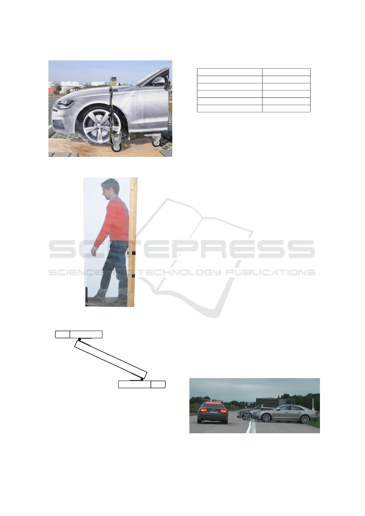
Figure 9: Exemplary CAPLOS dummy obstacle: passenger
car.
Figure 10: Exemplary CAPLOS dummy obstacle: pedes-
trian.
Figure 11: Schematic diagram of the hinge-construction be-
tween pushing rod and dummy obstacle.
hinge-construction compensates for unevenness of
the ground.
Table 1 shows mechanical property data based on
static and dynamic simulations of the facility.
Table 1: Performance data from simulation.
mean speed 3 m/s
maximum speed 10 m/s
minimum distance 0.8 m
maximum distance 1.3 m
minimum piston power 1120 N (2 bar)
maximum piston power 5600 N (10 bar)
4 SUITABILITY OF CAPLOS
Suitability of CAPLOS for the simulation of lateral
incursion-based critical scenarios was evaluated using
data collected in a driving study that was conducted
on the test track of the Universitaet der Bundeswehr
Muenchen.
4.1 Driving Experiment
60 test subjects were instructed to drive along a
straight rural road with two lanes at 50 km/h. They
were told that the object of the study was to examine
differences in lane keeping between right-hand and
left-hand traffic with a left-handed vehicle. CAPLOS
was hidden from sight behind a stationary car parking
perpendicularly at the side of the road approximately
100m from the exit of the double lane change traf-
fic cone corridor. The subject car was instrumented
with an inertial measurement unit fed with GPS as
well as dGPS correction data from a nearby base sta-
tion, ensuring an accuracy of at least 0.02m in posi-
tional tracking. When the combination of the car’s
distance to the known position of CAPLOS and its
current speed yielded a TTC of 1.6s or less, CAPLOS
was activated via a WiFi connection. Once CAPLOS
was activated, a fotorealistic silhouette of a passenger
car was pushed out into the road, partly blocking the
subject car’s lane and forcing the driver to react to the
suddenly appearing obstacle in order to avoid colli-
sion (Fig. 12). Four groups of 12 test subjects each
experienced different system-induced warnings in re-
action to the obstacle, the remaining 12 test subjects
were left unassisted.
Figure 12: CAPLOS in action.
CAPLOS - Compressed Air Powered Lateral Obstacle Simulator
75
The test subjects experienced this situation a sec-
ond time after a series of uneventful laps. Data from
both expositions was used to evaluate CAPLOS’s
suitability for the simulation of critical cross-traffic
scenarios in test subject driving studies.
4.2 Suitability Measures and Results
Reliability regarding the positioning of the dummy
obstacle is assumed to be near perfect, as it is held
firmly in place by the mechanical build of CAPLOS
and the length of stroke is set to a fixed value by the
length of the cylinder pistons and the transformation
ratio within the lever construction.
As a first measure of suitability, the machine’s re-
liability was ascertained using video data from a car-
mounted camera capturing the scene in front of the
subject car from 60 experimental trials with different
temperature and weather conditions. Frame-by-frame
analysis was used to determine when the dummy car
first started moving and when it reached its further-
most position, yielding the machine’s reaction time
(time between the subject car falling below a TTC
of 1.6s and first movement of the CAPLOS dummy
obstacle) and its expansion time (time between first
movement of the dummy obstacle and its reaching the
fully expanded position) respectively.
Both reaction time (n=60, M=0.406s, SD=0.040s)
and expansion time (n=60, M=0.726s, SD=0.066s)
were found to be highly reliable despite variance
caused by differences in latencies of the WiFi signal
(which can not be controlled), differences in air pres-
sure (pressure in the pressure tank was only replen-
ished to its nominal value once it fell below a certain
threshold, allowing for some variance), low data fre-
quency (frame rate of the video feed was 25 frames
per second, resulting in 0.04s steps of analysis) and
possible observer imprecision (especially regarding
first movement of the CAPLOS dummy obstacle).
No such data were publicly available from similar
existing machines for comparison. Performance was
therefore compared to previous preliminary tests. The
setup used mere positional triggering (not accounting
for the exact subject car speed) and a lab assistant to
tip over a rubber foam obstacle onto the road. Af-
ter an extensive training phase, twenty sets of five tri-
als each were performed over the course of two days.
Only the third to fifth trials from each set were used
for comparison. Four of these sixty trials failed. In
the remaining, ’reaction time’ (time between subject
car dropping below desired TTC and first obstacle
movement) was, unsurprisingly, found to vary to a
much greater extent (n=56, SD=0.284s). Also, ’ex-
pansion time’ (time between first movement of the
obstacle and its reaching the final position) was found
to be similar on average, but also more varied (n=56,
M=0.753s, SD=0.172s).
As a second measure of suitability, it was ascer-
tained whether the situation induced by the sudden
appearance of the CAPLOS dummy obstacle was per-
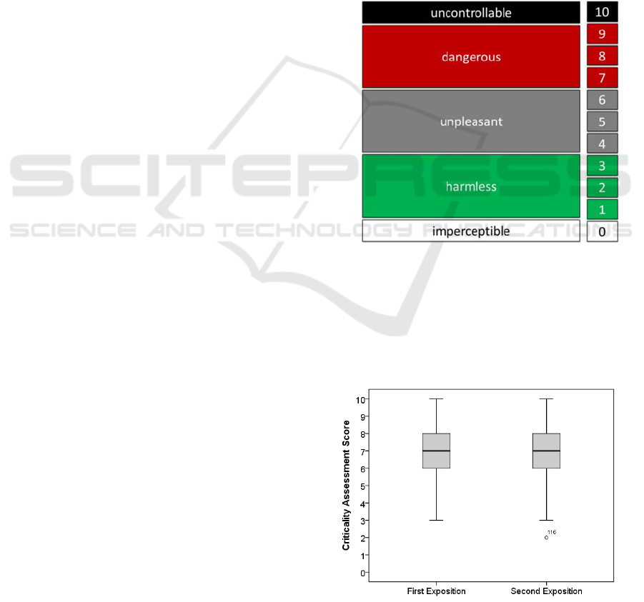
ceived as critical by the test subjects. Drivers were
asked to judge the criticality of the experienced situa-
tion using the scale for criticality assessment of driv-
ing and traffic scenarios (Neukum et al., 2008), where
test subjects first classify the situation as either imper-
ceptible, harmless, unpleasant, dangerous, or uncon-
trollable and, in a second step, indicate possible ten-
dencies towards a lower or higher category within the
three middle categories, resulting in a 11-point scale
(Fig. 13).
Figure 13: Scale for criticality assessment of driving and
traffic scenarios (Neukum et al., 2008).
In total, less than 5% of the test subjects rated the
experienced situation as harmless. Almost two thirds
(63%) rated the situation as dangerous or uncontrol-
lable. Fig. 14 shows the test subjects’ ratings for each
exposition to CAPLOS in a box plot.
Figure 14: Criticality ratings.
VEHITS 2016 - International Conference on Vehicle Technology and Intelligent Transport Systems
76
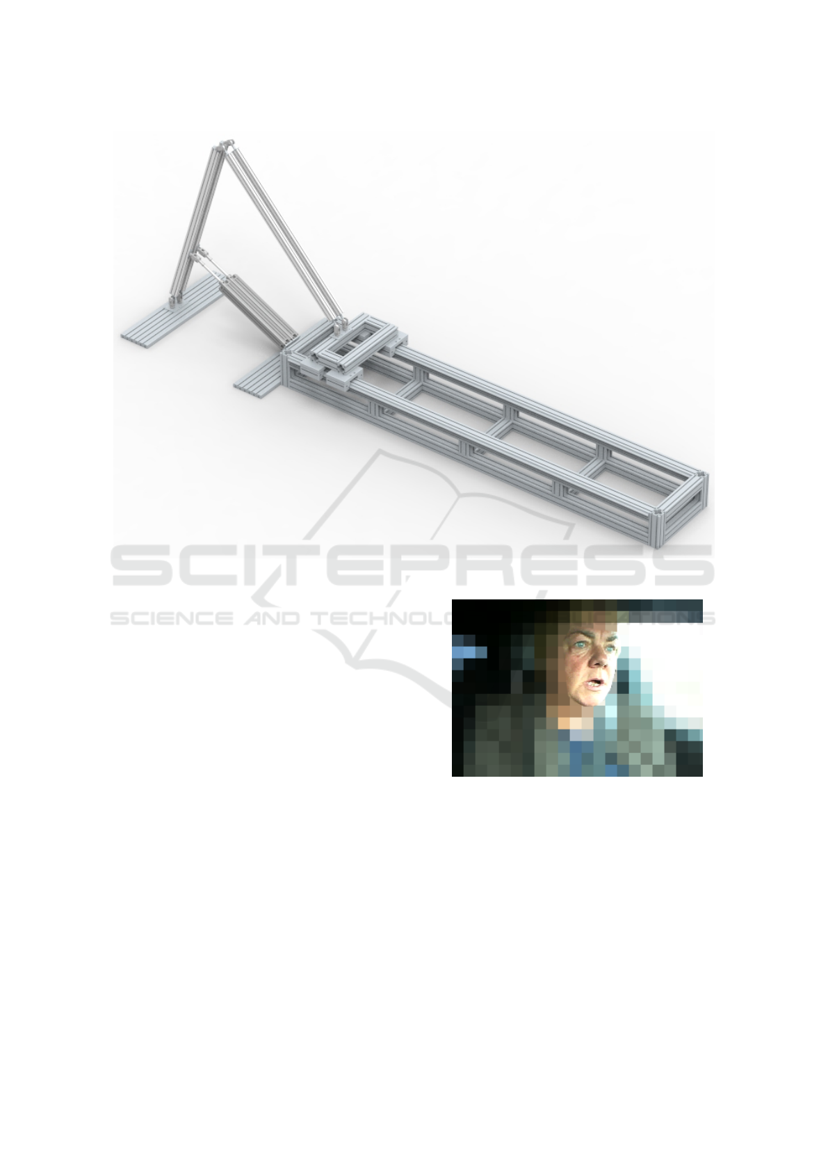
Figure 16: CAD-model of the improved CAPLOSm (Walter, 2015).
As a third measure of suitability it was ascertained
whether the test subjects were surprised by the crit-
ical situation induced by CAPLOS. The Facial Ac-
tion Code (Ekman and Friesen, 1976) is a system
developed for measuring all facial movement using
anatomically based ’action units’. Noticeable raising
of the inner as well as the outer eye-brows, widen-
ing of the eyes by raising of the upper eye-lid, and
dropping of the jaw (corresponding to action units
1, 2, 5, and 26 in the Facial Action Coding System
(Ekman et al., 2002) respectively) were regarded as
signs of surprise (or fear) in subjects’ facial expres-
sions (Fig. 15) in response to the CAPLOS dummy
obstacle’s moving into the road. Facial expressions
were recorded by a camera aimed at the driver with a
frequency of 25 frames per second and were analyzed
in slow motion (50% speed).
Even in the second exposition to CAPLOS 49 out
of 60 test subjects were found to show perceivable
signs of surprise in facial expression. The relative
amount was even higher (11 out of 12) for the unas-
sisted group, providing evidence that the surprise was
in response to the critical situation elicited by CAP-
LOS and not to the sudden intervention of an assis-
tance system.
Figure 15: Exemplary subject facial expression in reaction
to CAPLOS exposition.
5 CONCLUSION
The presented setup for CAPLOS constitutes a low-
cost test facility that permits reliable sudden position-
ing of different types of safe-to-crash dummy obsta-
cles with different triggering options. The data col-
lected in a driving study featuring CAPLOS further
provide evidence, that CAPLOS is able to create traf-
fic scenarios which test subjects view as critical and
surprising. Bearing in mind that these data are based
CAPLOS - Compressed Air Powered Lateral Obstacle Simulator
77
on multiple expositions to CAPLOS without active
distraction of the drivers, the authors conclude that
CAPLOS can be regarded as a valuable instrument
suitable for user studies in active safety ADAS devel-
opment and evaluation.
This setup of CAPLOS was, however, built partly
from scrap materials and parts scavenged from other
machinery and was therefore restricted in regard to
optimal design. The authors’ newest work includes
the construction of a new mobile version of CAPLOS
(CAPLOSm Fig. 16) mounted on top of a trailer. This
allows for a more efficient and more robust base de-
sign (Fig. 17) as well as further significant improve-
ment concerning ease of deployment. A change in the
leverarm design (Fig. 18) allows for greater variation
in extension length. Moreover, the authors intend to
include a mobile power source with CAPLOSm for
independent operation in any location.
Figure 17: New robust base design of CAPLOSm (Walter,
2015).
Figure 18: CAPLOSm - leverarm and piston mechanism
(Walter, 2015).
REFERENCES
Eckert, A., Hartmann, B., Sevenich, M., and Rieth, P.
(2011). Emergency steer & brake assist: a system-
atic approach for system integration of two comple-
mentary driver assistance systems. Washington DC.
International Technical Conference on the Enhanced
Safety of Vehicles.
Ekman, P. and Friesen, W. V. (1976). Measuring facial
movement. pages 56–75. Environmental Psychology
and Nonverbal Behavior.
Ekman, P., Friesen, W. V., and Hager, J. C. (2002). Facial
action coding system: The manual on cd rom. Salt
Lake City.
Hoffmann, J. and Winner, H. (2008). Evita - Das Unter-
suchungswerkzeug fuer Gefahrensituationen. Garch-
ing. Aktive Sicherheit durch Fahrerassistenz.
Koenig, W. (2012). Nutzergerechte Entwicklung der
Mensch-Maschine-Interaktion von Fahrerassisten-
zsystemen. In Handbuch Fahrerassistenzsysteme,
pages 33–42, Wiesbaden. Vieweg+Teubner Verlag.
Neukum, A., Luebbeke, T., Krueger, H.-P., Mayser, C., and
Steinle, J. (2008). Acc-stop&go: Fahrerverhalten an
funktionalen Systemgrenzen. pages 141–150. Work-
shop Fahrerassistenzsysteme.
Schmitt, J., Faerber, B., Maurer, M., and Breu, A. (2006).
Menschliches und technisches Verhalten an den Sys-
temgrenzen eines FAS. pages 1960:563–579. VDI-
Berichte.
Schreiber, P. (2015). Entwicklung einer mechanischen Ap-
paratur zur Darstellung ploetzlicher Hindernisse im
Rahmen der Fahrerassistenzerprobung (student work).
Neubiberg. Human Factors Institute, Universitaet der
Bundeswehr Muenchen.
Walter, M. (2015). Bau und Dokumentation einer Versuch-
sapparatur zur Fahrerassistenzssystemerprobung (stu-
dent work). Neubiberg. Human Factors Institute, Uni-
versitaet der Bundeswehr Muenchen.
VEHITS 2016 - International Conference on Vehicle Technology and Intelligent Transport Systems
78
