
A Method for Reusing TOSCA-based Applications and Management
Plans
Sebastian Wagner, Uwe Breitenb¨ucher and Frank Leymann
IAAS, University of Stuttgart, Universitaetsstr. 38, Stuttgart, Germany
Keywords:
Cloud Management, TOSCA, Workflow Reusability, Process Consolidation.
Abstract:
The automated provisioning and management of Cloud applications is supported by various general-purpose
technologies that provide generic management functionalities such as scaling components or automatically re-
deploying parts of a Cloud application. However, if complex applications have to be managed, these technolo-
gies reach their limits and individual, application-specific processes must be created to automate the execution
of holistic management tasks that cannot be implemented in a generic manner. Unfortunately, creating such
processes from scratch is time-consuming, error-prone, and knowledge-intensive, thus, leading to inefficient
developments of new applications. In this paper, we present an approach that tackles these issues by enabling
the usage of choreographies to systematically combine available management workflows of existing applica-
tion building blocks. Moreover, we show how these choreographies can be merged into single, executable
workflows in order to enable their automated execution. To validate the approach, we apply the concept to
the choreography language BPEL4CHOR and the Cloud standard TOSCA. In addition, we extend the Cloud
application management ecosystem OpenTOSCA to support executing management choreographies.
1 INTRODUCTION
Due to the steadily increasing use of information tech-
nology in enterprises, accurate development, provi-
sioning, and management of applications becomes of
crucial importance to align business and IT. While
developing application components and modelling
application architectures and designs is supported
by sophisticated tools, application management still
presents major challenges: Especially in Cloud Com-
puting, management automation is a key prerequisite
since manual management is (i) too slow to preserve
Cloud properties such as elasticity and (ii) too error-
prone as human operator errors account for the largest
fraction of failures in distributed systems (Brown and
Patterson, 2001)(Oppenheimer et al., 2003). Thus,
management automation is a key incentive in modern
IT.
While various management technologies
1
exist
that are capable of automating generic management
tasks, such as automatically scaling application com-
ponents or installing single software components, the
1
E.g., configuration management technologies such as
Chef (Opscode, Inc., 2015) or Puppet (Puppet Labs,
Inc., 2015), or Cloud management platforms such as
Heroku (Coutermarsh, 2014)
automation of complex, holistic, and application-
specific management processes is an open issue. Au-
tomating complex management processes, e.g., mi-
grating an application component from one Cloud to
another while avoiding downtime or acquiring new li-
cences for employed software components, typically
requires the orchestration of multiple heterogeneous
management technologies. Therefore, such manage-
ment processes are mostly implemented using work-
flows languages (Leymann and Roller, 2000), e. g.,
BPEL (Keller and Badonnel, 2004) or BPMN (Kopp
et al., 2012), since other approaches such as scripts
are not capable of providing the reliability and robust-
ness of the workflow technology (Herry et al., 2011).
Creating management processes, however, re-
quires integrating the different invocation mecha-
nisms, data formats, and transport protocols of each
employed technology, which needs enormous time
and expertise on the conceptual as well as on the
technical implementation level (Breitenb¨ucher et al.,
2013).
To avoid continually reinventing the wheel for
problemsthat havebeen already solved multiple times
for other applications, developing new applications
by reusing and combining proven (i) structural ap-
plication fragments as well as (ii) the corresponding
Wagner, S., Breitenbücher, U. and Leymann, F.
A Method for Reusing TOSCA-based Applications and Management Plans.
In Proceedings of the 6th International Conference on Cloud Computing and Services Science (CLOSER 2016) - Volume 2, pages 181-191
ISBN: 978-989-758-182-3
Copyright
c
2016 by SCITEPRESS – Science and Technology Publications, Lda. All rights reserved
181

available management processes would pave the way
to increase the efficiency and quality of new devel-
opments. However, while automatically combining
and merging individual application structures is re-
solved (
Binz et al., 2013a), integrating the associated
management processes is a highly non-trivial task that
still has to be done manually. Unfortunately, simi-
larly to manually authoring such processes, this leads
to error-prone, time-consuming, and costly efforts,
which is not appropriate for modern software devel-
opment and operation.
In this paper, we tackle these issues. We first
present a method that describes how to employ chore-
ographies to systematically reuse existing manage-
ment workflows. Choreography models enable coor-
dinating the distributed execution of individual work-
flows without the need to adapt their implementa-
tion. Thus, they provide a suitable integration basis
to combine different management workflows without
the need to dive into or change their technical imple-
mentation.
Since choreographies are not intended to be ex-
ecuted on a single workflow engine—which is a
mandatory requirement in application management as
typically sensitive data such as credentials or certifi-
cates have to be exchanged between the coordinated
workflows—we present a process consolidation ap-
proach that transforms a choreography including all
coordinated workflow models into one single exe-
cutable workflow model. The consolidation results
also in a faster execution due to reduced communica-
tion over the wire. It also simplifies deployment as
only a single workflow has to be deployed instead of
various interacting workflowsalong with the choreog-
raphy specification itself. Thus, reusing management
workflowsfollowing this approachleads to significant
time and cost savings when developing new applica-
tions out of existing building blocks.
To validate the presented approach, we apply
the developed concepts to the choreography mod-
elling language BPEL4CHOR (
Decker et al., 2007)
and the Cloud standard TOSCA (OASIS, 2013b;
OASIS, 2013a). For this purpose, we developed a
standard-based, open-source Cloud application man-
agement prototype by extending the OpenTOSCA
ecosystem (
Binz et al., 2013b; Kopp et al., 2013; Bre-
itenb¨ucher et al., 2014
) in order to support managing
applications based on choreographies, that are trans-
parently transformed into executable workflows be-
hind the scenes.
The remainder is structured as follows.
Sec-
tion 2
provides background and related work infor-
mation along with a motivating scenario. In
Sec-
tion 3, we conceptually describe the method for
reusing TOSCA-based applications and their manage-
ment plans by introducing management choreogra-
phies. In
Section 4 we formally discuss the step of
the method, that transforms a choreography into an
executable management plan. Section
5 validates the
method proposed in Section 3 and Section 6 con-
cludes the work.
2 BACKGROUND & RELATED
WORK
This section discusses background and related work
about (i) the Cloud standard TOSCA, (ii) manage-
ment workflows, and (iii) the transformation and con-
solidation of choreographies. In
Section 2.3, we in-
troduce a motivating scenario that is used throughout
the paper to explain the approach.
2.1 TOSCA and Management Plans
In this section, we introduce the Topology and
Orchestration Specification for Cloud Applications
(TOSCA), which is an emerging standard to describe
Cloud applications and their management. We ex-
plain the fundamental concepts of TOSCA that are
required to understand the contributions of this pa-
per and simplify constructs, where possible, for the
sake of comprehension. For more details, we refer
interested readers to the TOSCA Specification (OA-
SIS, 2013b
) and the TOSCA Primer (OASIS, 2013a).
TOSCA defines a meta-model for describing (i) the
structure of an application, and (ii) their management
processes. In addition, the standard introduces an
archive format that enables packaging applications
and all required files, e. g., installables, as portable
archive that can be consumed by TOSCA runtimes to
provision and manage new instances of the described
application. The structure of the application is de-
scribed in the form of an application topology, a di-
rected graph that consists of vertices representing the
components of the application and edges that describe
the relationships between these components, e. g., that
a Webserver component is installed on an operating
system. Components and relationships are typed and
may specify properties and management operations
to be invoked. For example, a component of type
ApacheWebserver may specify its IP-address as well
as the HTTP-port and provides an operation to deploy
new applications. In addition, required artifacts, e. g.,
installation scripts or binaries implementing the appli-
cation functionality, may be associated with the corre-
sponding components, relationships, and operations.
CLOSER 2016 - 6th International Conference on Cloud Computing and Services Science
182
RAM: 4GB
Cores: 2
…
HTTP-Port: 8080
Credentials: […]
(hostedOn)
(ApacheWebserver)
(Ubuntu12.04VM)
(OpenStack)
Provisioning Plan
Create
VM
Install
Webserver
Install PHP
Module
Deploy PHP
Application
(PHPModule)
(PHP)
(dependsOn)
(installedOn)
(hostedOn)
(hostedOn)
Read Topology
Properties
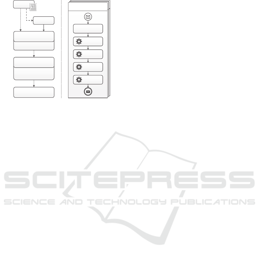
Figure 1: TOSCA Example: Topology (left) and provision-
ing plan (right).
Thereby, TOSCA enables describing the entire struc-
ture of an application in the form of a self-contained
model, which also contains all information about em-
ployed types, properties, files, and operations. These
models can be used by a TOSCA runtime to fully
automatically provision instances of the application
by interpreting the semantics of the modeled struc-
ture (
OASIS, 2013a; Breitenb¨ucher et al., 2014).
Fig. 1 shows an example on the left rendered us-
ing VINO4TOSCA (
Breitenb¨ucher et al., 2012). The
shown topology describes a deployment consisting of
a PHP application that is hosted on an ApacheWeb-
server running on a virtual machine (VM) of type
Ubuntu12.04VM. This VM is operated by the Cloud
management system OpenStack. To run the PHP ap-
plication on an Apache Webserver, a PHPModule
needs to be installed. In the topology the component
types and relationship types, e. g., the desired hoste-
dOn, of the VM, are put in brackets. The component
properties, e. g., the desired RAM of the VM, are de-
picted below the component types. The actual appli-
cation implementation, i.e., the PHP files implement-
ing the functionality, is attached to the PHP compo-
nent.
While the provisioning of simple applications can
be described implicitly by such topology models,
TOSCA also enables describing complex provision-
ing and management processes in the form of explic-
itly modeled management plans. Management plans
are executable workflows that specify the (i) activities
to be executed, (ii) the control flow between them,
i. e., their execution order, as well as (iii) the data
flow, e. g., that one activity produces data to be con-
sumed by a subsequent activity (
Leymann and Roller,
2000
). There exists standardized workflow languages
and corresponding engines, for example, BPEL (OA-
SIS, 2007) or BPMN (OMG, 2011), that enable de-
scribing workflows in a portable manner. Standard-
compliant workflow engines can be employed to auto-
matically execute these workflow models. The work-
flow technology is well-known for features such as re-
liability and robustness (
Leymann and Roller, 2000),
thus, providing an ideal basis to automate manage-
ment processes (
Keller and Badonnel, 2004). In ad-
dition, there are extensions of workflow standards
which are explicitly tailored to the management of
applications. For example, BPMN4TOSCA (
Kopp
et al., 2012) is an extension to easily describe man-
agement plans for applications modeled in TOSCA.
TOSCA supports using arbitrary workflow languages
for describing executable management plans (
OASIS,
2013b).
Fig. 1 shows a simplified management workflow
on the right that automatically provisions the appli-
cation (data flow modeling is omitted for simplic-
ity). The first activity reads properties of components
and relationships from the topology model, which
enables customizing the deployment without adapt-
ing the plan. Other information, e.g., the endpoint
of Open Stack, are passed via the plan’s start mes-
sage. Using these information, the plan instantiates
a new virtual machine by invoking the HTTP-API
of Open Stack. Afterwards, the plan uses SSH to
access the virtual machine and installs the Apache
Webserver and the PHP module using Chef (
Opscode,
Inc., 2015
), a configuration management technology.
Finally, the application files, which have been ex-
tracted from the topology, are deployed on the Web-
server and the application’s endpoint is returned.
The TOSCA standard additionally defines an ex-
change format to package topology models, types,
management plans and all required files in the form
of a Cloud Service Archive (CSAR) (
OASIS, 2013b;
OASIS, 2013a). These archives are portable across
standards-compliant TOSCA runtimes and provide
the basis to automatically provision and manage in-
stances of the modeled application. Runtimes such
as OpenTOSCA (
Binz et al., 2013b) also enable
automatically executing the associated management
workflows, thereby, enabling the automation of the
entire lifecycle of Cloud applications described in
TOSCA. Thus, TOSCA provides an ideal basis for
systematically reusing (i) proven application struc-
tures as well as their (ii) management processes as
both can be described and linked using the standard.
2.2 Choreography Transformation
There exist manual approaches for transforming
choreographies to executable processes (plans).
A Method for Reusing TOSCA-based Applications and Management Plans
183
RAM: 4GB
Cores: 2
…
HTTP-Port: 8080
Credentials: […]
(hostedOn)
(ApacheWebserver)
(Ubuntu12.04VM)
(OpenStack)
(PHPModule)
(PHP)
(dependsOn)
(installedOn)
(hostedOn)
(hostedOn)
RAM: 4GB
Cores: 2
…
(hostedOn)
HTTP-Port: 8080
Credentials: […]
(MySQLDBMS)
(Ubuntu12.04VM)
(hostedOn)
HTTP-Port: 8080
Credentials: […]
(MySQLDB)
(hostedOn)
(OpenStack)
(SQLConnection)
PHP Provisioning Plan
Create
VM
Install
Webserver
Install PHP
Module
Deploy PHP
Application
Read Topology
Properties
MySQL Provisioning Plan
Create
VM
Install
MySQLDBMS
Create DB
Instance
Insert DB
Schema
Read Topology
Properties
Cloud Application Archive for PHP Application on Open Stack Cloud Application Archive for MySQL Database on Open Stack
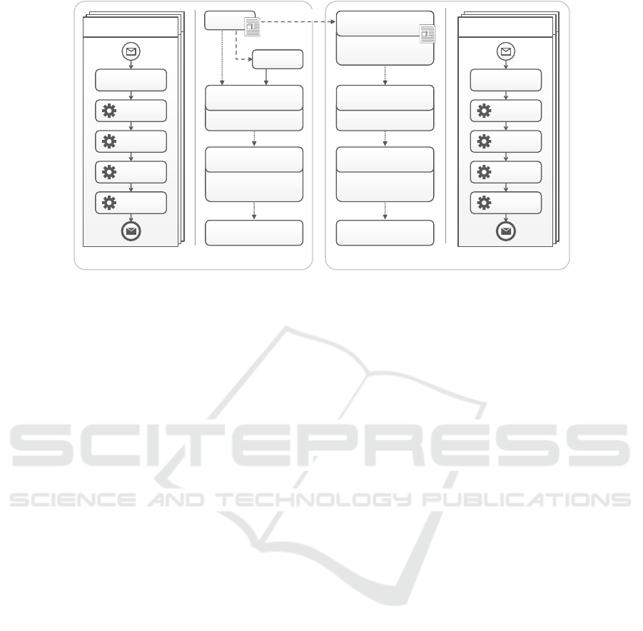
Figure 2: Motivating scenario showing that management plans have to be combined to reuse existing topology models and
management processes.
Hofreiter et al. (
Hofreiter and Huemer, 2008) sug-
gest for instance a top-down approach where business
partners agree on a global choreography by specify-
ing the interaction behavior the processes of the part-
ners have to comply with. The choreography and the
corresponding processes have to be modeled in UML
and the authors propose a manual transformation to
BPEL. Mendling et al. (
Mendling and Hafner, 2008)
use the Web Service Choreography Description Lan-
guage (WS-CDL) (
Kavantzas et al., 2005) to model
choreographies and to generate BPEL process stubs
out of it. However, these process stubs have to be
also completed manually. Another drawback of WS-
CDL is that it is an interaction choreography which
is less expressive than interconnection models as we
will briefly discuss in
Section 3.3.
In
Section 4 a process consolidation algorithm is
presented to generate an executable process from a
choreography. Existing process consolidation tech-
niques, e. g., from K¨uster et al. (
K¨uster et al., 2008)
or Mendling and Simon (
Mendling and Simon, 2006),
focus on merging semantically equivalent processes,
which is different from the proposed consolidation
algorithm that merges complementing processes of a
choreography into a single process.
In contrast to our approach Herry et al. (
Herry
et al., 2013) aim to execute a former centralized man-
agement workflow in a decentralized fashion. To ac-
complish that they are describing an approach to de-
compose the management workflow into a set of dif-
ferent interacting agents coordinating its execution.
2.3 Motivating Scenario
This section describes a motivation scenario based
on the previous example to explain the difficulties
of implementing executable management plans and
the significant advantage that would be enabled by
an approach that facilitates systematically reusing and
combining existing workflows. As described be-
fore, for provisioning the PHP-based example ap-
plication several management tasks have to be per-
formed: Open Stack’s HTTP-API has to be invoked
for instantiating the VM while SSH and Chef are
used to install the Webserver. However, already
this simple example impressively shows the difficul-
ties: Two low-level management technologies includ-
ing their invocation mechanisms, data formats, and
transport protocols have to be (i) understood and
(ii) orchestrated by a workflow. This requires com-
plex data format transformations, building integration
wrappers to invoke the technologies, and results in
many lines of complex workflow code (
Breitenb¨ucher
et al., 2013). Thus, implementing such manage-
ment plans from scratch is a labor-intensive, error-
prone, and complex task that requires a lot of exper-
tise in very different fields of technologies - reach-
ing from high-level orchestration to low-level applica-
tion management. Therefore, systematically reusing
existing plans and combining them and coordinating
them would significantly improve these deficiencies.
Fig. 2 shows an example how TOSCA may
support this vision. On the left, the provisioning
plan and the topology of the TOSCA example in-
troduced in
Section 2.1 is shown. On the right, a
topology is shown that describes the deployment of
a MySQL database including the corresponding pro-
CLOSER 2016 - 6th International Conference on Cloud Computing and Services Science
184

Application
Developer
Application
Developer
1. Manual Modelling Phase 2. Automated Execution Phase
Select and Merge
TOSCA Topology Models
A
Connect Merged
Parts of the Application
B
Coordinate Management
Plans by Choreographies
C
Transform
Choreographies Into
Executable Workflows
D
Deploy and Execute
Resulting Workflows
E
Application
Manager
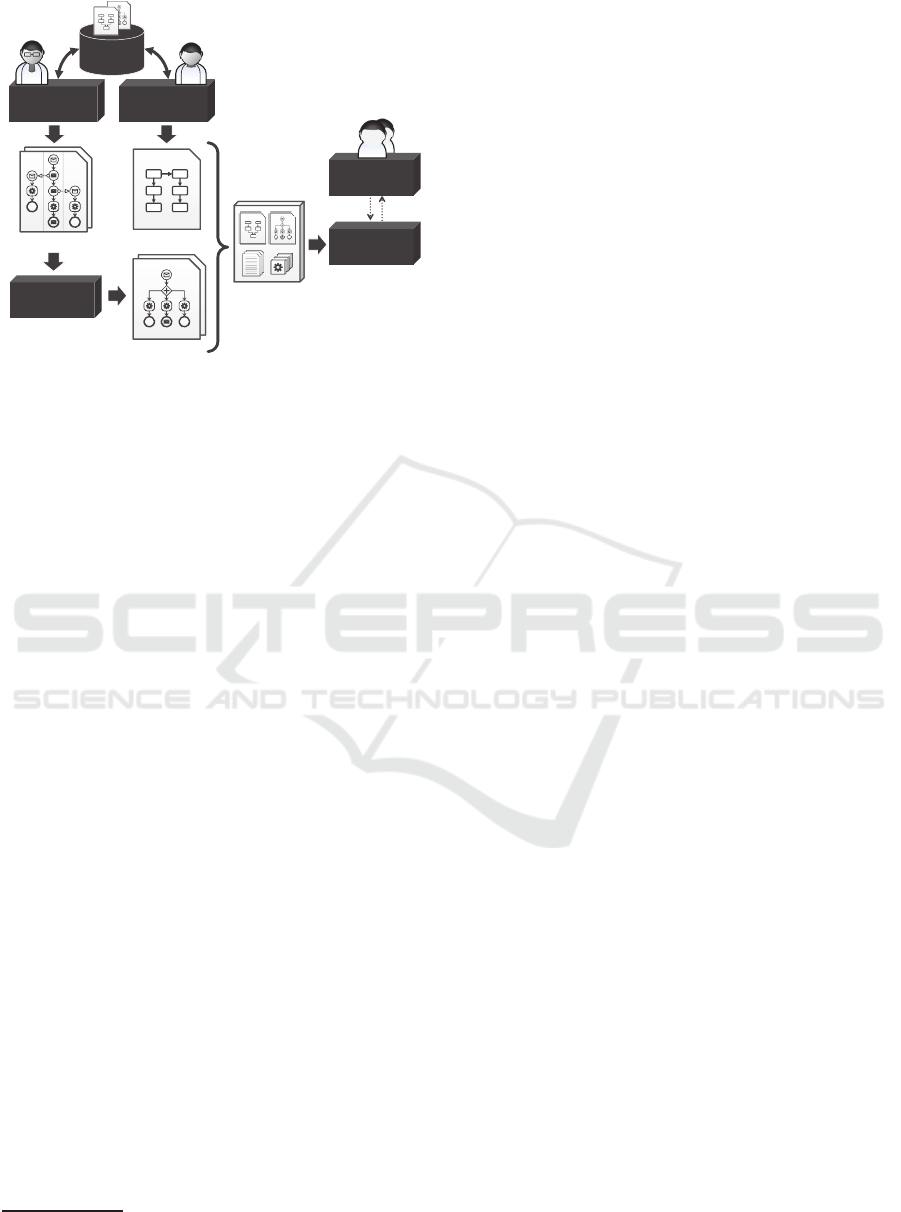
Figure 3: Steps of the method to systematically reuse TOSCA-based (i) application topologies and (ii) their corresponding
management plans.
visioning plan. This plan automatically provisions a
new VM, installs the MySQL database management
system, creates a new database, and inserts a specified
schema, which is attached to the MySQL component.
Thus, if a LAMP-application
2
has to be developed,
the two topologies could be merged and connected
with a new relationship of type SQLConnection. Ob-
viously, to provision the combined stack, also their
provisioning plans have to be combined. However,
while merging TOSCA topology models can be done
easily using tools such as Winery (
Kopp et al., 2013),
manually combining workflow models is a crucial
and error-prone task since (i) the individual control
flows and possible violations have to be considered,
(ii) low-level artifacts, e.g., XML schema definitions,
have to be imported, and (iii) typically hundreds of
lines of workflow code have to be integrated. Han-
dling these issues manually is neither efficient nor re-
liable. Therefore, a systematic approach for combin-
ing TOSCA topologies and management plans is re-
quired that enables combining plans without the need
to deal with their actual implementation.
3 A METHOD TO REUSE
TOSCA-BASED APPLICATIONS
This section presents a generic method to systemat-
ically reuse existing TOSCA-based topology models
and their management plans as building blocks for the
development of new applications. The method is sub-
divided in two phases and shown in
Fig. 3: (i) a man-
ual modeling phase, which describes how application
developers and manager model new applications by
reusing existing topology models and plans, and (ii)
an automated execution phase, which enables auto-
matically deploying and managing the modeled ap-
plication. The five steps of the method are explained
in detail in the following.
2
An application consisting of L
inux, Apache, MySQL,
P
HP components
3.1 Select and Merge TOSCA Topology
Models
In the first step, the application developer sketches the
desired deployment and selects appropriate TOSCA
topology models from a repository to be used for
its realization. The selected topologies are merged
by copying them into a new topology model, which
provides a recursive aggregation model as the result
is also a topology that can be combined with others
again. This is a manual step that may be supported
by TOSCA modeling tools such as the open-source
implementation Winery (Kopp et al., 2013). In pre-
vious works, we showed how multiple application
topologies can be merged automatically while pre-
serving their functional semantics (
Binz et al., 2013a)
and how valid implementations for custom compo-
nent types can be derived automatically from a repos-
itory of validated cloud application topologies (
Sol-
dani et al., 2015). These works support technically
merging individual topologies, but the general deci-
sions which topologies to be used are of manual na-
ture as only developers are aware of the desired over-
all functionality of the application to be developed.
3.2 Connect Merged Parts of the
Application
The resulting topology model contains isolated topol-
ogy fragments that may have to be connected with
each other. For example, the motivating scenario re-
quires the insertion of a SQLConnection relationship
to syntactically connect the merged topology models.
Using well-defined relationship types enables speci-
fying the respective semantics. This is also a man-
ual step as these connections exclusively depend on
the desired functionality. Moreover, TOSCA enables
specifying requirements and capabilities of compo-
nents, which can be used to automatically derive pos-
sible connections (OASIS, 2013a). Modeling tools
may use these specifications to support combining the
individual fragments, but in many cases the final de-
cisions must be made manually by the application de-
velopers. For example, if multiple business compo-
A Method for Reusing TOSCA-based Applications and Management Plans
185

nents and databases exist, in general, a modeling tool
cannot derive with certainty which component has to
connect to which database.
3.3 Coordinate Management Plans by
Choreographies
Similarly to connecting isolated topology fragments,
their management plans need to be combined for real-
izing holistic management processes that affect larger
parts of the merged application at once, for example,
to terminate the whole application. However, as dis-
cussed in
Section 2.3, manually merging workflow
models is a highly non-trivial and technically error-
prone task. Therefore, we propose using intercon-
nection choreographies to coordinate the individual
workflows without changing their actual implemen-
tation. Interconnection choreographies define inter-
action specifications for collaborating processes by
interconnecting communication activities, i.e., send
and receive activities, of these processes via set of
message links
3
. This enables modeling different in-
teraction styles between the individual management
workflows, e. g., asynchronous and synchronous in-
teractions. Thus, in this step, (i) application man-
agers analyse required management processes, (ii) se-
lect appropriate management workflows of the indi-
vidual topology models, and (iii) coordinate them by
modeling choreographies. In addition, (iv) depending
on required input and output parameters of the indi-
vidual workflows, the data flow between the work-
flow invocations has to be specified. For example,
the MySQL provisioning workflow of the motivating
scenario outputs the endpoint and credentials of the
database, which are required to invoke a management
plan of the PHP model that connects the PHP frontend
to this database
4
. This is a manual step as the desired
functionality, in general, cannot be derived automati-
cally for application-specific tasks. For example, the
individual provisioning plans of the motivating sce-
nario can be used to model the overall provisioning
of the entire application as well as to implement man-
agement plans that scale out parts of the application
to handle changing workloads.
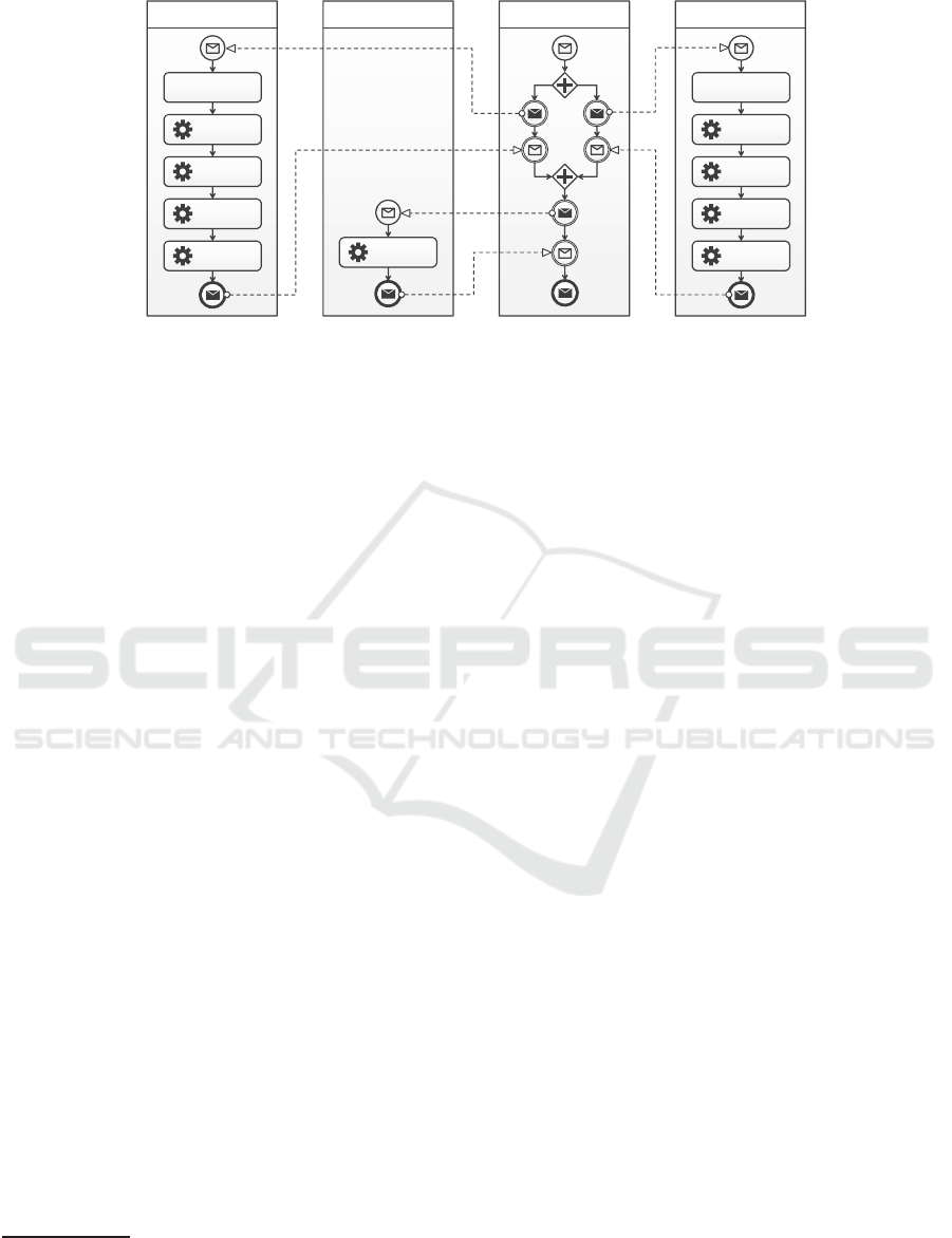
Fig. 4 shows an example of a choreography that
3
In contrast to interaction choreographies that model
message exchanges as abstract interactions not considering
the workflow implementation.
4
Such management workflows can be realized in a
generic manner by binding them exclusively to operations
defined by the respective component type. TOSCA enables
exchanging the implementations of these operations on the
topology layer to implement application-specific manage-
ment logic.
coordinates three management workflows of the mo-
tivating scenario. The coordination plan invokes in
parallel the provisioning workflows of the PHP and
MySQL topology models, respectively, by specifying
message links to their receive activities. After their
execution, messages are sent back to the coordina-
tion plan, which continues with invoking the afore-
mentioned management workflow for transferring the
database information (endpoint, database name, and
credentials) to the PHP application by invoking the
corresponding management operation.
3.4 Transform Choreographies Into
Executable Workflows
After manually modeling the choreography, the re-
sulting model has to be transformed into an exe-
cutable workflow. This has to be done as choreogra-
phies are not suited to be executed on a single work-
flow machine: unnecessary communication effort be-
tween the different workflows would slow down the
execution time (
Wagner et al., 2013) and passing sen-
sitive data over the wire, e. g., the database creden-
tials, is not appropriate. Therefore, in this step, the
choreography is automatically translated into an exe-
cutable workflow model. This transformation is de-
scribed in the next section in detail and implemented
by our prototype.
3.5 Deploy and Execute Resulting
Workflows
In the last step, the generated workflow model is de-
ployed on an appropriate workflow engine. After-
wards, the plan can be triggered by sending the start
message to the workflow’s endpoint. TOSCA run-
times such as OpenTOSCA (Binz et al., 2013b) ex-
plicitly support management by executing such work-
flows.
4 PROCESS CONSOLIDATION
To transform the management choreography into an
executable workflow we provide an algorithm in Sec-
tion 4.2
that implements the process consolidation ap-
proach described in (Wagner et al., 2012) and (Wag-
ner et al., 2014
). In Section 4.3 the algorithm is
applied on the provisioning choreography shown in
Fig. 4.
CLOSER 2016 - 6th International Conference on Cloud Computing and Services Science
186
PHPSetDBEndpointPlanPHPProvisioningPlan
Create
VM
Install
Webserver
InstallPHP
Module
DeployPHP
Application
ReadTopology
Properties
MySQLProvisioningPlan
Create
VM
Install
MySQLDBMS
CreateDB
Instance
InsertDB
Schema
ReadTopology
Properties
InvokeSetDB
Operation
CoordinationPlan
Figure 4: Provisioning choreography coordinating three management workflows of the PHP and MySQL TOSCA models.
4.1 Choreography Meta-model
The algorithm bases on the interconnection choreog-
raphy meta-model that is defined in the following.
The choreography meta-model uses the process meta-
model introduced by (Leymann and Roller, 2000) as
foundation. For simplicity reasons constructs such
as compensation spheres or loops are omitted in this
meta-model.
Definition 1 (Process). A process p = (A, E, L, Cond)
is a directed acyclic graph where A is the set of activ-
ities. E ⊆ A× A is the set of directed control links be-
tween two activities. If two activities are not directly
or indirectly related over control links they are per-
formed concurrently. L denotes the set of labels used
to identify process elements and Cond denotes the set
of conditions used within p that can be evaluated to
true or false.
Definition 2 (Activity). An activity a ∈ A is defined by
the tuple a = (name, type, jc) where name ∈ L, jc ∈
Cond, type ∈ T and T = {send,receive, task,
noop, opaque, sphere}.
The set A
send
⊂ A represents all activities of type
send
. These activities send messages to another pro-
cess via a message link ml ∈ M L. The messages can
be received by
receive
activities A
rcv
⊂ A. A
send
supports either the asynchronous or synchronous one-
to-one interaction
5
pattern (Barros et al., 2005). The
asynchronous
send
activity sends a message to the
receive
within the other process in a “fire and for-
get” manner, i.e., after the message was sent the
send
completes and its successor activities are performed.
A synchronous
send
activity, in turn, waits until it re-
ceives a response from the called partner process be-
5
In one-to-one interactions a send activity sends a mes-
sage to exactly one receive activity, while in one-to-many
interactions a send activity communicates with multiple re-
ceives, e.g., via loops.
fore its successors can be executed, i. e., it “blocks”
until the response is received. Response messages to
synchronous calls must be answered by another
send
activity following the
receive
in the control flow. A
task
activity a ∈ A
task
⊂ A performs certain manage-
ment logic, such as executing human tasks, calling
scripts etc. An
opaque
activity acts as placeholder
for concrete business functions and
noop
activities do
not perform any business functions.
The set of incoming control links of an activity
a are denoted as E
→
(a) = {(a
i
, a, c)| (a
i
, a, c) ∈ E}.
The set of outgoing control links of a is denoted as
E
←
(a) = {(a, a
i
, c) |(a, a
i
, c) ∈ E}. The join condi-
tion of an activity can be obtained with the function
joinCond : A → Cond.
Definition 3 (Fault-Handling Sphere). A fault han-
dling sphere s ∈ S ⊂ A is an activity that groups a
set of activities and defines a common fault handling
behavior on them. A sphere is defined by the tuple
s = (A, E, FH) where A denotes the set of grouped
activities and E the links between them. If an ac-
tivity within a sphere throws a fault, all other ac-
tivities within this sphere are terminated. The set
FH ⊆ (L ∪ {⊥}) × A × E represents the set of fault
handlers attached to a sphere. A fault handler fh =
( faultName, A, E) reacts on a fault with a defined
name f aultName ∈ L that may be thrown by the activ-
ities within the sphere. A sphere may have one fault
handler attached where faultName = ⊥. It reacts
on all faults being not caught by the other fault han-
dlers. The fault handling logic consists of the fault
handling activities and the links between them. The
name of a fault handler can be obtained with the func-
tion faultName : FH → L.
The child activities of a process, a sphere or a fault
handler can be obtained with the function children :
P ∪ S ∪ FH → A. Accordingly, the function links :
P ∪S∪FH → E returns the control links between the
A Method for Reusing TOSCA-based Applications and Management Plans
187

activities. Note, for simplicity reasons we assume that
control links are defined within the same modeling
construct as their source and target activities. This
implies that no control link must cross the boundary
of a modeling construct.
Definition 4 (Choreography). A choreography C ∈ C
is defined by the tuple C = (P , M L), i.e., it con-
sists of a set of interacting processes P and the mes-
sage links M L between them. A message link ml
connects a sending and a receiving activity: M L ⊂
A
send
× A
rcv
. ∀ml ∈ M L : P
1
6= P
2
∧ P
1
, P
2
∈ P where
P
1
= proc ess(A
send
), P
2
= proc ess(A
rcv
). A message
link is activated when the sending activity a
send
∈
A
send
is started. A receiving activity a
rcv
∈ A
rcv
can-
not complete until its incoming message link was ac-
tivated.
The process defined within a choreography can be
obtained with the function processes : C → P . The
functions send : M L → A
send
and receive : M L →
A
rcv
return the send and receive activity of a given
message link.
4.2 Choreography-based Process
Consolidation
The process consolidation operation gets a choreog-
raphy as input and returns a single process P
µ
. The
operation ensures that P
µ
contains all activities A
task
defined within the processes of C and that the execu-
tion order between these activities is preserved, i.e., ,
P
µ
is able to generate the same set of activity traces of
A
task
during runtime as C (
Wagner et al., 2012; ?). As
the consolidation steps were only described conceptu-
ally in previous works, we provide a formal descrip-
tion of the consolidation steps in
Algorithm 1. Note,
since the implementation of data flow is language-
dependent the algorithm focuses only on the control
flow aspects of the consolidation.
First the process P
µ
is created and all activi-
ties of C along with the control links between them
are moved to P
µ
(lines
10 and 11). The activities
A
i
and A
j
originating from different processes in C
(process(A
i
) 6= proce ss(A
j
)) have to be isolated from
each other in P
µ
. This ensures that the originally mod-
eled behavior is preserved, that faults in A
i
are not
propagated to activities from A
j
, which would lead
to their termination. The isolation is guaranteed by
adding spheres for each process P to be merged. The
spheres act as container for the activity graph of P.
Each of these spheres has a fault handler attached to
it catching all faults that may be thrown from the ac-
tivities within the sphere.
Then the control flow materialization is performed
which derivesthe control flow between activities orig-
Algorithm 1: Process Consolidation.
1: procedure CONSOLIDATE(C)
2: P
µ
← new Process
3: for all P ∈ processes(C) do
4: s ← new
sphere
5: children(s) ← children(P)
6: fh ← new
faultHandler
7: children( fh) ← {new
noop
}
8: faultName( f h) ← ⊥
9: faultHandlers(s) ← faultHandlers(P) ∪ { fh}
10: children(P
µ
) ← children(P
µ
) ∪ {s}
11: links(P
µ
) ← links(P
µ
) ∪ links(P)
12: end for
13: for all ml ∈ messageLinks(C) do
14: send ← send(ml)
15: rcv ← receive(ml)
16: ML
rp
← {mess ageLinks(C)|
receive(ml) = send}
17: if ML
rp
6=
/
0 then
18: MATERIALIZESYN(send, receive, ML
rp
)
19: else
20: MATERIALIZEASYN(send, receive)
21: end if
22: end for
23: CLEANUP(P
µ
)
24: end procedure
inating from different processes from the interaction
patterns defined in C. Therefore, Algorithm 1 visits
each message link (line
13), determines the interac-
tion pattern implied by it and calls the correspond-
ing materialization operation. If the visited message
link ml originates from a sending activity that is also
target of one or more other message links ML
rp
this
implies a synchronous interaction ML
rp
. In this case
the response for the request made over ml is sent via
one of the message links in ML
rp
. Due to space rea-
sons only the materialization for asynchronous inter-
actions is described in the following. A more detailed
description of the materialization for synchronous in-
teractions (called in line
18) can be found in (Wagner
et al., 2012
).
The materialization for asynchronous interactions
is implemented by
Algorithm 2. The algorithm re-
places the communication activities send and receive
with the synchronization activities syn
s
and syn
rc
. Ac-
tivity syn
s
serves as synchronization point for the con-
trol links of the former send, thus, it inherits the con-
trol links and join condition of the send activity. Ac-
tivity syn
rc
gets the control links and join condition
of the receive assigned (lines
6 to 8). This preserves
the control flow order between the predecessor and
successor activities of the former receive. To emu-
late the control flow constraint implied by an asyn-
CLOSER 2016 - 6th International Conference on Cloud Computing and Services Science
188
LAMPProvisioning Plan(P
µ
)
Create
VM
Install
Webserver
InstallPHP
Module
DeployPHP
Application
ReadTopology
Properties
Create
VM
Install
MySQLDBMS
CreateDB
Instance
InsertDB
Schema
ReadTopology
Properties
InvokeSetDB
Operation
e1
syn
e2
syn
e3
syn
e4
syn
e5
syn
e6
syn
LAMPProvisioning Plan(P
µ
)
Create
VM
Install
Webserver
InstallPHP
Module
DeployPHP
Application
ReadTopology
Properties
Create
VM
Install
MySQLDBMS
CreateDB
Instance
InsertDB
Schema
ReadTopology
Properties
Invoke SetDB
Operation
CleanUp
syn6
s
e1
syn
e2
syn
e3
syn
e4
syn
e6
syn
e5
syn
syn1
rc
syn2
s
syn1
s
syn2
rc
syn5
rc
syn5
s
syn3
s
syn3
rcͲ
syn4
rc
syn4
s
syn6
rc
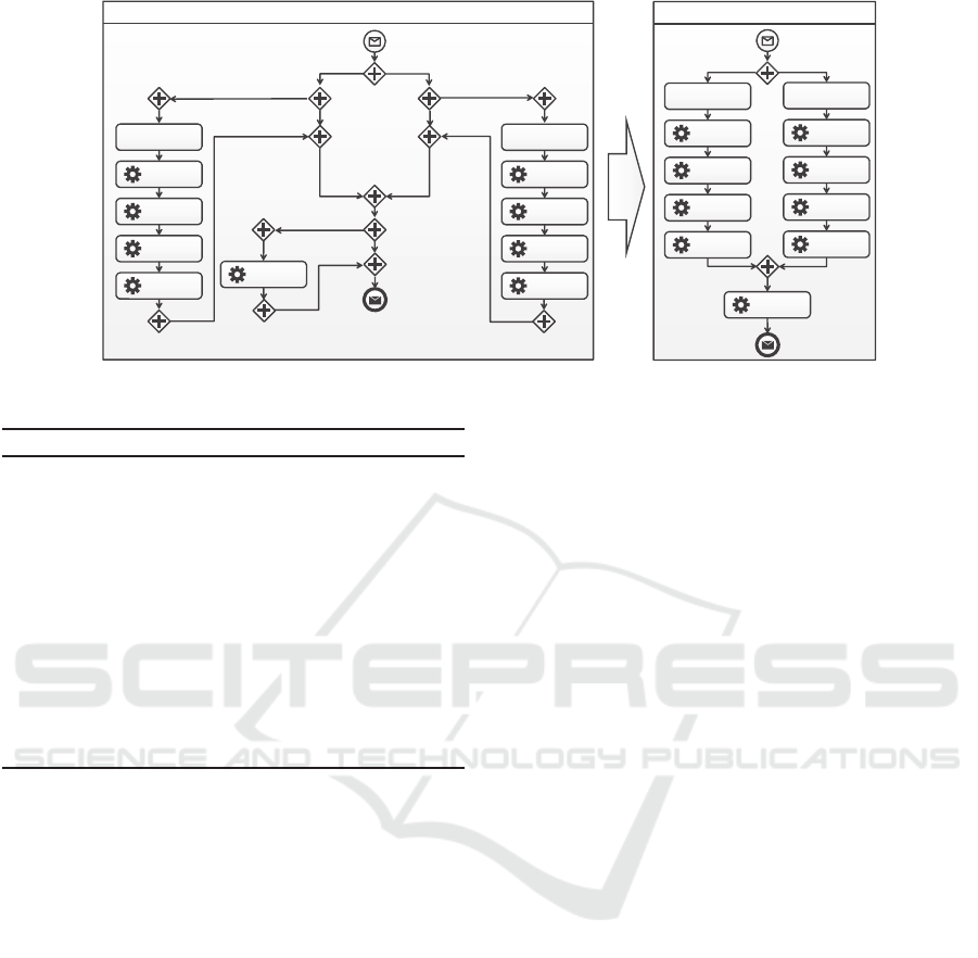
Figure 5: Consolidation of provisioning choreography into single LAMP provisioning plan.
Algorithm 2: Asynchronous Control Flow Materialization.
1: procedure MATERIALIZEASYN(send, receive)
2: syn
s
← new
opaque
3: syn
rc
← new
opaque
4: children(P
µ
) ← ch ildren(P
µ
) − send − receive
5: e
syn
= new
link
(syn
s
, syn
rc
,
true
)
6: E
→
(syn
s
) ← E
→
(send)
7: E
←
(syn
s
) ← E
←
(send) ∪ e
syn
8: joinCond(syn
s
) ← joinCo nd(send)
9: E
→
(syn
rc
) ← E
→
(receive) ∪ e
syn
10: E
←
(syn
rc
) ← E
←
(receive)
11: joinCond(syn
rc
) ← joinCond(receive) AND e
syn
12: end procedure
chronous interaction, i. e., that successor activities of
the former receive are not started before the message
was sent over the message link, a new control link
e
syn
is created between syn
s
and syn
rc
. The synchro-
nization activities are of type
opaque
as their imple-
mentation is language-dependent. For instance when
BPMN choreographies are consolidated, the type of
syn
s
is a branching parallel gateway and the type of
syn
rc
is a merging parallel gateway.
After the control flow materialization was per-
formed the process consolidation can complete. How-
ever, we introduce an additional optional “clean up”
(optimization) step in line 23 for decreasing the com-
plexity and for improving the readability of P
µ
. This
may be for instance achieved by removing redundant
activities and control links that were created during
the consolidation. This step is language dependent
and not further discussed here but an example is given
below.
4.3 Consolidation Example
The single process LAMP Provisioning Plan on the
left of
Fig. 5 results from the application of Al-
gorithm 1
on the provisioning choreography. As
all plans interact asynchronously via message links
ml1 to ml6 the asynchronous control flow ma-
terialization is applied. Thus, the sending and
receiving activities related to each message link
are replaced with synchronization activity pairs
(syn1
s
, syn1
rc
), . . . , (syn6
s
, syn6
rc
). The correspond-
ing control links e1
syn
, . . . , e6
syn
ensure that the con-
trol flow order implied by the message links is pre-
served. The new control links e2
syn
and e4
syn
along
with join conditions (not depicted in
Fig. 4) guarantee
for instance that Invoke SetDB Operation is not exe-
cuted before the other management tasks completed.
As stated before, depending on the workflow lan-
guage,
Algorithm 1 may create redundantcontrol flow
constructs that can be removed from P
µ
. The LAMP
provisioning plan on the left of
Fig. 5 contains some
redundancies, for instance redundant branching paral-
lel gateways (with just one outgoing link) and merg-
ing parallel gateways (with just one incoming link).
The concrete optimization (clean up) mechanism for
BPMN models is out of scope of this work and is just
shown in an exemplary manner. The results of the op-
timization is the LAMP provisioning plan on the right
of Fig. 5. The plan preserves the control flow order
between the activities that was specified in the man-
agement choreography presented in
Fig. 4. For the
sake of clarity, the spheres isolating activities origi-
nating from different plans are not shown in
Fig. 5.
A Method for Reusing TOSCA-based Applications and Management Plans
189
TOSCACSAR
TopologyModel
Winery
ModellingTool
Choreographies
Management
Work
f
lows
Choreography
ModellingTool
Choreography
Consolidation
OpenTOSCA
Container
Vinothek
Portal
TOSCA
Repository
Application
Developer
Application
Manager
End
Users
Figure 6: Architecture of the open-source Cloud manage-
ment prototype.
5 VALIDATION
In this section, we validate the practical feasibility of
the presented method by a prototypical implementa-
tion. We applied the method and merge algorithms to
the choreography modeling language BPEL4CHOR
and extended the OpenTOSCA Cloud management
ecosystem to support choreographies. This ecosystem
consists of (i) the graphical TOSCA modelling tool
Winery (
Kopp et al., 2013), the (ii) OpenTOSCA con-
tainer (Binz et al., 2013b), and (iii) the self-service
portal Vinothek (
Breitenb¨ucher et al., 2014). An
overview of the entire prototype is shown in Fig. 6:
Application developers use Winery to merge exist-
ing topology models, while application managers use
the choreographymodelling tool ChorDesigner (
Weiß
and Karastoyanova, 2014
) to coordinate the associ-
ated management workflows.
Based on the merge algorithm described in
Sec-
tion 4 a process consolidation tool was developed for
generating a single executable BPEL processes out of
a choreography
6
. Therefore the algorithm was ex-
tended to accommodate the language idiosyncrasies
of BPEL. This includes the emulation of the chore-
ography’s data flow in the merged process and the
elimination of language violations that may arise dur-
ing control flow materialization, e. g., control links
crossing boundaries of loops. Beside asynchronous
and synchronous one-to-one interactions the tool does
also support the consolidation of one-to-many inter-
actions (
Barros et al., 2005) (Wagner et al., 2014).
The merged topology model as well as the gen-
6
The prototype is available as Open-source: https://git
hub.com/wagnerse/chormerge
erated management plans can be packaged as CSAR
using Winery. The resulting CSAR can be installed on
the OpenTOSCA container, which internally deploys
the workflows and, thereby, makes them executable.
To ease the invocation of provisioning and manage-
ment workflows, we employ our TOSCA self-service
portal Vinothek, which wraps the invocation of work-
flows by a simple user interface for end users. All
tools are available as open-source implementations,
thus, the developed prototype provides an end-to-
end Cloud application management system support-
ing choreographies for modelling coordinated man-
agement processes.
6 CONCLUSION AND FUTURE
WORK
To ease the development of new complex TOSCA-
based applications, we described a semi-automatic
method for building such applications by reusing ex-
isting application topologies and management plans.
Beside describing how existing applications can be
selected and wired, management choreographieswere
introduced for enabling the coordinated execution of
existing management plans. To achieve the efficient
execution of the management choreography on a sin-
gle workflow engine, an automatic process consoli-
dation algorithm for transforming the choreography
into a single executable management plan was sug-
gested. The method was validated by a prototype
consisting of different tools supporting the execution
of the different steps of the method. For validating
the approach BPEL4Chor was used as choreography
language as the OpenTOSCA ecosystem currently
only supports BPEL management plans and chore-
ographies. Since BPEL4Chor has the same model-
ing capabilities as BPMN collaborations (
Kopp et al.,
2011
), the presented method can be also applied on
BPMN processes and collaborations, if BPMN sup-
port will be added to the ecosystem. In future work,
we plan to create orchestrations from low-level man-
agement scripts to enable the systematic reusability of
artifacts on different levels of provisioning and man-
agement granularity.
ACKNOWLEDGEMENTS
This work was partially funded by the BMWi project
NEMAR (03ET40188) and the DFG project SitOPT
(610872).
CLOSER 2016 - 6th International Conference on Cloud Computing and Services Science
190

REFERENCES
Barros, A., Dumas, M., and terHofstede, A. (2005). Service
Interaction Patterns. In BPM. Springer.
Binz, T., Breitenb¨ucher, U., Kopp, O., Leymann, F., and
Weiß, A. (2013a). Improve Resource-Sharing through
Functionality-Preserving Merge of Cloud Application
Topologies. In CLOSER. SciTePress.
Binz, T. et al. (2013b). OpenTOSCA – a runtime
for TOSCA-based cloud applications. In ICSOC.
Springer.
Breitenb¨ucher, U., Binz, T., Kopp, O., Leymann, F., and
Wettinger, J. (2013). Integrated cloud application pro-
visioning: Interconnecting service-centric and script-
centric management technologies. In CoopIS, pages
130–148. Springer.
Breitenb¨ucher, U. et al. (2012). Vino4TOSCA: A visual
notation for application topologies based on TOSCA.
In CoopIS, pages 416–424. Springer.
Breitenb¨ucher, U. et al. (2014). Combining Declarative and
Imperative Cloud Application Provisioning based on
TOSCA. In IC2E.
Breitenb¨ucher, U. et al. (2014). Vinothek – a self-service
portal for TOSCA. In ZEUS. CEUR.
Brown, A. B. and Patterson, D. A. (2001). To err is human.
In EASY, page 5.
Coutermarsh, M. (2014). Heroku Cookbook. Packt Publish-
ing Ltd.
Decker, G., Kopp, O., Leymann, F., and Weske, M. (2007).
BPEL4Chor: Extending BPEL for modeling chore-
ographies. In ICWS, pages 296–303. IEEE.
Herry, H., Anderson, P., and Rovatsos, M. (2013). Chore-
ographing configuration changes. In Proceedings of
the 9th International Conference on Network and Ser-
vice Management, CNSM 2013, Zurich, Switzerland,
October 14-18, 2013, pages 156–160.
Herry, H., Anderson, P., and Wickler, G. (2011). Automated
planning for configuration changes. In LISA.
Hofreiter, B. and Huemer, C. (2008). A model-driven top-
down approach to inter-organizational systems: From
global choreography models to executable BPEL. In
CEC.
Kavantzas, N., Burdett, D., Ritzinger, G., Fletcher, T., La-
fon, Y., and Barreto, C. (2005). Web Services Chore-
ography Description Language Version 1.0.
Keller, A. and Badonnel, R. (2004). Automating the pro-
visioning of application services with the BPEL4WS
workflow language. In DSOM.
Kopp, O., Binz, T., Breitenb¨ucher, U., and Leymann, F.
(2012). BPMN4TOSCA: A domain-specific language
to model management plans for composite applica-
tions. In BPMN.
Kopp, O. et al. (2013). Winery – modeling tool for TOSCA-
based cloud applications. In ICSOC. Springer.
Kopp, O., Leymann, F., and Wagner, S. (2011). Model-
ing choreogaphies: BPMN 2.0 versus BPEL-based
approaches. In Proceedings of the 4
th
International
Workshop on Enterprise Modelling and Information
Systems Architectures - EMISA 2011, Lecture Notes
in Informatics (LNI). Gesellschaft f¨ur Informatik e.V.
(GI).
K¨uster, J., Gerth, C., F¨orster, A., and Engels, G. (2008). A
tool for process merging in business-driven develop-
ment. In Proceedings of the Forum at the CAiSE.
Leymann, F. and Roller, D. (2000). Production workflow:
concepts and techniques. Prentice Hall PTR.
Mendling, J. and Hafner, M. (2008). From WS-CDL chore-
ography to BPEL process orchestration. J. Enterprise
Inf. Management, 21(5):525–542.
Mendling, J. and Simon, C. (2006). Business process design
by view integration. In BPM Workshops. Springer.
OASIS (2007). Web Services Business Process Execution
Language (WS-BPEL) Version 2.0. OASIS.
OASIS (2013a). TOSCA Primer v1.0. http://docs.oasis-
open.org/tosca/tosca-primer/v1.0/tosca-primer-
v1.0.html.
OASIS (2013b). TOSCA v1.0. http://docs.oasis-
open.org/tosca/TOSCA/v1.0/os/TOSCA-v1.0-
os.html.
OMG (2011). Business Process Model and Notation
(BPMN), Version 2.0.
Oppenheimer, D., Ganapathi, A., and Patterson, D. A.
(2003). Why do internet services fail, and what can
be done about it? In USITS.
Opscode, Inc. (2015). Chef official site:
http://www.opscode.com/chef.
Puppet Labs, Inc. (2015). Puppet official site:
http://puppetlabs.com/puppet/what-is-puppet.
Soldani, J., Binz, T., Breitenb¨ucher, U., Leymann, F., and
Brogi, A. (2015). Tosca-mart: A method for adapt-
ing and reusing cloud applications. Technical report,
University of Pisa.
Wagner, S., Kopp, O., and Leymann, F. (2012). Towards
Verification of Process Merge Patterns with Allen’s
Interval Algebra. In ZEUS. CEUR.
Wagner, S., Kopp, O., and Leymann, F. (2014).
Choreography-based Consolidation of Multi-Instance
BPEL Processes. In CLOSER. SciTePress.
Wagner, S., Roller, D., Kopp, O., Unger, T., and Leymann,
F. (2013). Performance optimizations for interacting
business processes. In IC2E. IEEE.
Weiß, A. and Karastoyanova, D. (2014). Enabling coupled
multi-scale, multi-field experiments through chore-
ographies of data-driven scientific simulations. Com-
puting, pages 1–29.
A Method for Reusing TOSCA-based Applications and Management Plans
191
