
A Methodology for Model-based Development and Safety Analysis of
Transport Systems
Simon Hordvik
1
, Kristoffer Øseth
1
, Jan Olaf Blech
2
and Peter Herrmann
1
1
Norwegian University of Science and Technology, Trondheim, Norway
2
RMIT University, Melbourne, Australia
Keywords:
Software Engineering, Spatial Modeling, Cyber-physical Systems.
Abstract:
We present a method to engineer the control software of transport systems and analyze their safety using the
Reactive Blocks framework. The development benefits from the model-based approach and makes the analysis
of the systems at design time possible. The software is analyzed for freedom of collisions and other spatiotem-
poral properties by combining test runs of already existing devices to find out their physical constraints with
the analysis of simulation runs using the verification tool BeSpaceD. This allows us to discover potential safety
hazards already during the development of the control software. In particular, we introduce a methodology for
the engineering and safety analysis of transportation systems and elaborate its practical usability by means of
a demonstrator based on Lego Mindstorms.
1 INTRODUCTION
In the development of control software for transport
and other cyber-physical systems, safety is a ma-
jor challenge to achieve (Lee, 2008). Particularly,
one has to analyze the software for compliance with
spatiotemporal properties like guaranteeing a suffi-
cient safety distance between devices at all times.
This is mostly achieved by intensive and costly test-
ing of the software for functional and quality of ser-
vice attributes. To ease the analysis effort, we sup-
plement traditional test-based development by apply-
ing a model-based software engineering technique.
Its formal semantics facilitates the use of automatic
model-checking and provers that can detect flaws in
the control software. Since we perform the checks
on the models and not on the later code, these flaws,
which might be sources for violations of spatiotempo-
ral properties, are discovered early making the overall
development process more cost effective than plain
system testing.
As a model-driven development tool, we chose
Reactive Blocks (Kraemer et al., 2009). It provides
the ability to reuse and share building blocks. Fur-
ther, Reactive Blocks enables us to simulate data and
control flows, to model check the building blocks for
functional correctness, and to create executable code
automatically. Moreover, we use BeSpaceD (Blech
and Schmidt, 2014), which enables the verification of
spatiotemporal properties in safety-critical systems.
It has been deployed in several applications imple-
mented with Reactive Blocks and simulated in the
Java software environment, e.g., (Han et al., 2015;
Herrmann et al., 2016).
A contribution of this paper is a methodology that
defines the various engineering and analysis steps of
the control software development process. It allows
us to combine the analysis of kinematic behavior and
other data obtained by gauging existing devices with
the simulation and formal verification of the control
software in order to guarantee that a device fulfills
certain spatiotemporal properties. An example for
measured data is the worst-case braking distance of
a train that is observed by testing an actual unit. It is
directly considered in a BeSpaced verification prov-
ing that the control software causes the train to brake
sufficiently early such that collisions with other trains
are prevented.
We apply the methodology by developing the con-
trol software of a demonstrator which is built with
Lego Mindstorms together with additional sensors
and servers. Lego Mindstorms offers the necessary
hardware components needed to build a physical au-
tonomous rail-based system. It is an affordable way to
create demonstrators such as robots, that can be used
in hobby settings as well as research. Event-driven
software can be run on the Lego Mindstorms compo-
nents enabling the control entities to execute actions
Hordvik, S., Øseth, K., Blech, J. and Herrmann, P.
A Methodology for Model-based Development and Safety Analysis of Transport Systems.
In Proceedings of the 11th International Conference on Evaluation of Novel Software Approaches to Software Engineering (ENASE 2016), pages 91-101
ISBN: 978-989-758-189-2
Copyright
c
2016 by SCITEPRESS – Science and Technology Publications, Lda. All rights reserved
91

based on input received from the different types of
sensors. We describe the Lego Mindstorms demon-
strator as well as the various development steps fol-
lowing the methodology.
Reactive Blocks and BeSpaceD are introduced in
Sect. 2 followed by the presentation of the method-
ology in Sect. 3. In Sect. 4, the demonstrator is dis-
cussed while Sect. 5 describes the development of its
software based on the methodology. Section 6 refers
to experience with the approach and in Sect. 7 we
present related work. In Sect. 8, we conclude and
name some ideas for future work.
2 REACTIVE BLOCKS AND
BESPACED
The model-driven engineering technique Reactive
Blocks is a tool-set for the development of reac-
tive software systems (Kraemer et al., 2009). A
system model consists of an arbitrary number of
building blocks, i.e., models of subsystems or sub-
functionalities, that are composed with each other. A
major advantage of this modeling method is its reuse
potential since a building block can comprise sub-
functionality that is useful in many different applica-
tions. The building block is specified once, stored in
a tool library, and, when needed, moved into a system
model by simple drag and drop. The behavior of a
building block is modeled by UML activities that may
contain UML call behavior actions representing its in-
ner building blocks. These inner blocks are also spec-
ified by UML activities such that the approach scales.
The interface of a building block is specified by an
External State Machine (ESM) that describes the ab-
breviated interface behavior of the block (Kraemer
and Herrmann, 2009). To make analysis of functional
correctness by model checking possible, the activi-
ties and ESMs are supplemented with formal seman-
tics (Kraemer and Herrmann, 2010). Moreover, Re-
active Blocks enables the automatic transformation of
system models into well-performing Java code (Krae-
mer et al., 2006). Some tool extensions allow us to an-
alyze models also for safety (Sl
˚
atten et al., 2011) and
probabilistic real-time (Han et al., 2013; Han et al.,
2014) properties.
BeSpaceD is a constraint solving and non-
classical model checking framework (Blech and
Schmidt, 2014; Blech and Schmidt, 2013). It em-
phasizes particularly on dealing with models of cyber-
physical systems that usually comprise a large amount
of time and space-based aspects. BeSpaceD provides
a modeling language and a library to reason on mod-
els, using techniques such as state-space exploration,
Development of Initial Control Software
Prototype Testing of Initial Software
Development of Extended Control Software
Software Analysis with BeSpaceD
Transformation into Executable Code
Figure 1: Methodology overview.
abstraction and reduction. It enables the creation of
verification goals for SAT and SMT solvers and pro-
vides connections to these tools. Thus, these solvers
can be used based on much more concrete models
than their traditional inputs. On the other hand, Be-
SpaceD models are more abstract than typical use-
case specific (meta-)models that are used in case spe-
cific tools. From an expressiveness point of view, SAT
and SMT offer the specification elements of propo-
sitional logic (+ Presburger arithmetic (Presburger,
1929)). Semantically, using BeSpaceD the notions
of time and space are added. Other semantic carry-
ing elements are available: They are treated as predi-
cate parameters and have to be resolved in programs
building on the BeSpaceD frameworks or queries to
BeSpaceD.
BeSpaceD is written in Scala and compatible with
Eclipse/Java. The modeling language is based on
abstract datatypes and integrates with the Scala lan-
guage. It is possible to write one’s own programs that
construct BeSpaceD models and to write code using
BeSpaceD functionality for checking it. In fact, as
shown in (Herrmann et al., 2016; Han et al., 2014),
an extension of Reactive Blocks is able to transfer its
models to BeSpaceD models such that they can be di-
rectly analyzed for spatiotemporal properties.
3 METHODOLOGY
The creation of control software for transport systems
requires knowledge about central kinematic proper-
ties like braking distances or maximum accelerations.
Since the systems and their environments are often
too complex to gain such data exclusively by simu-
lation, it has to be gathered by testing and observing
prototypes. This feature is considered by our method-
ology (see Fig. 1). It consists of five major steps:
1. In parallel to the development of the physical de-
vice, an initial version of the control software is
engineered with Reactive Blocks. This first model
already contains several functions that will also be
ENASE 2016 - 11th International Conference on Evaluation of Novel Software Approaches to Software Engineering
92

used later in the final version, e.g., the access to
sensors and actuators. The functions guarantee-
ing safety, however, are either not implemented or
based on initial data concluded from simulations
resp. experience with previous versions.
2. Code is generated from the initial Reactive Blocks
model and used in the prototypes which are tested
in order to find out relevant kinematic properties.
3. When all relevant properties are observed, the
control software is extended. For that, we amend
the original Reactive Blocks model by adding
building blocks and flows. In this way, existing
sub-functionality will be preserved making the
development process cheaper.
4. The extended Reactive Blocks model is analyzed
by BeSpaceD for compliance with relevant spa-
tiotemporal properties. Depending on the com-
plexity of the verification runs, we may carry out
the proofs in two different ways:
(a) One extracts a descriptive formula of relevant
system functionality from the Reactive Blocks
model and transforms it into a format readable
by BeSpaceD. Afterwards, BeSpaceD verifies
that this specification keeps certain spatiotem-
poral properties. As shown in (Herrmann et al.,
2016), the extraction of the descriptive formu-
las can be carried out automatically if the Re-
active Blocks model was developed based on a
certain course of action and a set of dedicated
building blocks. Due to its completeness, this
kind of analysis is preferred but according to
the complexity of the problem might exceed the
capabilities of the solvers used by BeSpaceD.
(b) One composes the control software model with
a simulator that is also created in Reactive
Blocks (Han et al., 2014). Thus, several sim-
ulation runs can be performed and their logs
are translated into input for BeSpaceD that an-
alyzes the data for compliance with the spa-
tiotemporal properties. The log data can be
proved very efficiently (e.g., 10,000’s of dif-
ferent spatiotemporal coordinates within a split
second). But in contrast to the other solution,
this one is not exhaustive such that it can only
guarantee the preservation of the properties for
the simulated cases.
5. When the developed control software fulfills all
desired properties, the Reactive Blocks model
is transformed into code that is installed in the
transport devices and used for further certification
steps.
Depending on the kind of system, these steps can also
be iterated such that the control software is developed
4
1
3
2
Figure 2: Track control zones.
and analyzed in several cycles. Thanks to the fully
automatic nature of the code generation in Reactive
Blocks, the results of the engineering cycles can be
easily transformed into executable code.
Due to the importance of system safety for life
and limb of the later passengers, we do not see our
methodology as a replacement for traditional certifi-
cation but as a supplement. Yet, we expect that the
model-based development and spatiotemporal analy-
sis leads to a better quality of the produced software.
In consequence, the certification process will have to
deal with fewer software errors and therefore is get-
ting smoother.
4 DEMONSTRATOR
As mentioned in the introduction, we use the Lego
Mindstorms train-set to exemplify and evaluate our
methodology. The overall layout is sketched in Fig. 2.
It consists of five different stations that are connected
by up to four trains that all operate counterclockwise
albeit with possibly different speeds such that a train
might catch up with another one. A train set com-
prises a motor, wheels and a train body (see Fig. 3).
Further, we provide each train with a color sensor fac-
ing towards the tracks which can be seen on the right
side of Fig. 3. It enables the train to count sleep-
ers and to detect special sleepers that are furnished
with colored Lego bricks. The coordination of the
motor and the color sensor as well as the connection
with a wireless communication device is provided by
an EV3 controller, the standard control unit of Lego
Mindstorms. This unit is transported in one of the
cars.
As also shown in Fig. 2, the tracks are partitioned
into four zones marked by different colors. Each
of these zones is controlled by an EV3 unit which
coordinates all trains in its zone and prevents colli-
A Methodology for Model-based Development and Safety Analysis of Transport Systems
93
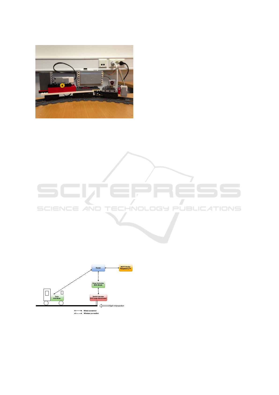
Figure 3: Example lego train.
sions. This resembles the procedure used in the Eu-
ropean Rail Traffic Management System (ERTMS), a
novel train control system to be used in all European
railway networks (ERTMS Project, 2015; UNIFE
Project, 2015). Moreover, the zone controller drives
the switch points in our system. The beginning of the
zones are marked by colored sleepers such that the
color sensors of a train can detect when a new zone is
entered.
The train controllers are connected with the
zone controllers by means of the Message Queuing
Telemetry Transport Protocol (MQTT) (MQTT.org,
2015). This is a popular machine-to-machine connec-
tivity protocol often used in the “Internet of Things”
domain. Usually, both the routing of connections and
the brokerage of users are done by a number of stan-
dard MQTT servers. Since tests, however, showed
that the use of these servers lead to an unacceptably
high transmission delay, we created our own MQTT
server that is realized on a Raspberry Pi (Upton and
Halfacree, 2014). Figure 4 sketches the communica-
tion architecture used. A detailed technical evalua-
tion of the demonstrator can be found in (Hordvik and
Øseth, 2015).
Figure 4: Communication architecture between trains and
zone controllers.
4.1 Routing Trains
Fig. 2 highlights that a station consists of two tracks.
A stopping track is linked to a platform that allows
passengers to enter and leave trains. A second track
makes it possible that a train not stopping may pass
the station while another one waits in it. Further, at
some points we have alternate routes, e.g., for trains
going from the station in zone 2 to the one in zone
4. Thus, the trains have to be routed which is done by
the zone controllers. For that, the demonstrator is split
into 23 different tracks that are each bordered by two
switch points. The beginning of each track is marked
by an unambiguously colored sleeper such that a train
can always follow up on which track it is currently
located. As shown in the message-sequence-chart in
Fig. 5, a train provides the responsible zone controller
with its destination. Based on that, the zone controller
selects the tracks, the train has to pass in its zone,
and sets the switch points accordingly. The routing
algorithm is based on work described in (Overskeid,
2015).
The switching of zones by a train is realized by
a sequence of colored sleepers as depicted in Fig. 6.
First, the train passes a green sleeper indicating that
not a new track is entered but that a zone shift is
coming up. Since a zone switch affords the time-
consuming establishment of a new connection be-
tween the train and zone controller, we use overlap-
ping segments in which the train is controlled by both
involved zone controllers. The beginning of the over-
lapped segment is marked by a sleeper in the color of
the new zone. When passing it, the train controller
starts building up a MQTT connection with the new
zone controller. The end of the overlapping segment
is identified by a colored sleeper that signals the be-
ginning of a new track in the newly entered zone. It
may only be passed if the connection with the con-
troller of the new zone is established and thereafter,
the link with the controller of the old zone is released.
4.2 Collision Avoidance
As mentioned above, the zone controllers are respon-
sible for preventing collisions of trains in their zone.
For that, they permanently need information about
the exact positions and speeds of the trains. Since
color sensors are the only sensing equipment used
in our demonstrator and Lego trains have the nice
feature that sleepers are always in the same distance
from each other irrespectively of the track shape, we
use the sleepers as means to define exact train posi-
tions. In particular, each train controller maintains a
so-called sleeper counter that totals how many regu-
ENASE 2016 - 11th International Conference on Evaluation of Novel Software Approaches to Software Engineering
94
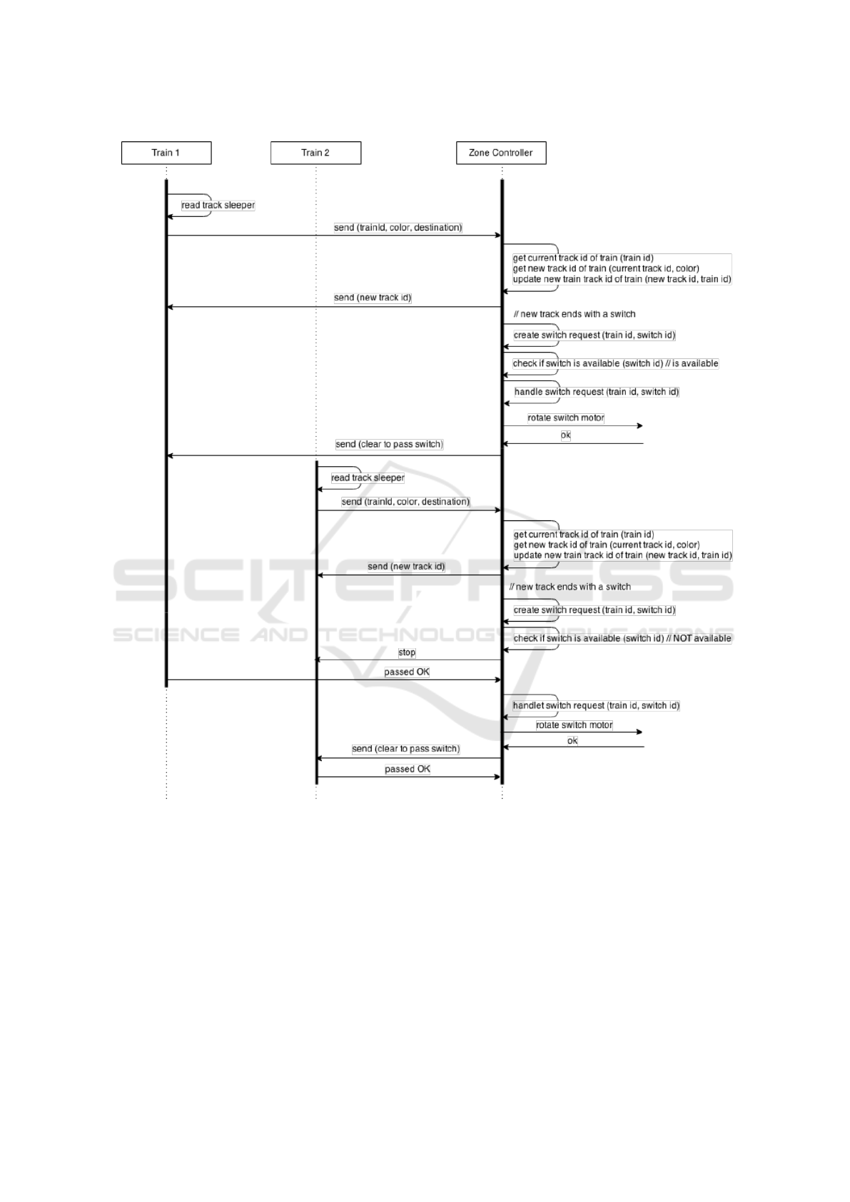
Figure 5: Two trains interacting with a zone controller.
lar, i.e., non-colored, sleepers of the track on which it
currently moves, it already passed. Further, by using
time-stamps and knowing the distance between the
sleepers, a train calculates its current speed. When-
ever a regular sleeper is passed, the train sends the
value of its sleeper counter and speed value to the re-
sponsible zone controller (resp. zone controllers if the
train is on an overlapping track), see Fig. 5.
From these data and its knowledge about the cur-
rent track of the train, the zone controller establishes
which sleeper the train just entered. It sets this sleeper
and, with help of the information about the train’s
length, all other sleepers that are covered by the train
into state occupied. Due to its knowledge about the
system layout, the zone controller may also consider
the sleepers of the previous track if the train just
passes a track border.
In addition, the sleepers vacated by the train since
the last notification was received, are set to free.
The zone controller checks if the train is on a colli-
sion course with another one. Based on the current
speed and position of the train, it calculates the dis-
A Methodology for Model-based Development and Safety Analysis of Transport Systems
95

Track 1 Track 2 Track 3
Zone 1
Zone 2
. . .
. . .
. . .
. . .
Green Track sleeeper
“New zone coming up”
Zone Sleeper
(either blue, yellow, green or red)
“Enter new zone”
Track Sleeper
(either blue, yellow, green or red)
“Leave previous zone”
Overlap
Figure 6: Sleepers indicating zone switches.
tance needed for the train to come to a complete stop.
This distance is converted into the number n of sleep-
ers that are passed before the train stands after cut-
ting power. Moreover, taking the communication de-
lay between the zone and train controllers into con-
sideration, we add a safety buffer b of sleepers
1
to n.
If at least one of the n + b buffers ahead of the train
is occupied, the zone controller sends immediately a
stop message to the train that initiates an emergency
stop. Of course, this holds also for sleepers in the
subsequent track when the train reaches the end of
the previous one. If all the next n + b buffers are not
occupied, an all-clear signal is sent, and the train may
continue with its current speed. Since the zone con-
troller may have been broken, the train it also stopped
when no signal at all arrives within a certain period of
time.
The logic also includes the option of using an ex-
tra buffer such that the zone controller will check the
state of sleepers that are even further in front of the
train. Are any of these sleepers occupied, the con-
troller commands the train to slow down, instead of
coming to a complete stop. If the blocking train in
front continues to stand still, the emergency break is
initiated a little closer to it due to the reduced speed,
which leads to a smoother operation.
5 ENGINEERING THE
CONTROLLERS OF THE
DEMONSTRATOR
The development of the control software for our
demonstrator followed tightly the methodology pre-
sented in Sect. 3.
1
It is important to note that, the bigger the safety buffer b
is, the more states of sleepers need to be checked, which
means more processing time and again a bigger latency
with regards to when the train receives a response. By test-
ing the braking distances of the trains with various safety
buffer values, we found out that b = 10 gives the best re-
sults.
Figure 7: Breaking distance for different speed levels.
5.1 Methodology Step 1
The creation of an initial software version profitted
strongly from work by (Overskeid, 2015) who devel-
oped building blocks that facilitated the handling of
the access to the EV3 train and zone controllers from
the Reactive Blocks model. These blocks could be
simply combined to achieve a first user-managed con-
trol system.
5.2 Methodology Step 2
We used the initial control software to find out the
relevant kinematic properties of the trains. In partic-
ular, we analyzed the stopping distances for five of
the seven speed levels
2
offered for Lego Mindstorms
trains. Fig. 7 depicts that, as expected, the braking
distances are parabolic albeit with a relatively small
gradient. Using these results and the fact that two
sleepers are in a distance of 32.5 cm, we could de-
termine the numbers n of sleepers to be considered
for each speed level in the collision avoidance scheme
discussed in Sect. 4.2.
Moreover, in this phase we examined the color
sensors more closely to get good readings. With re-
spect to speed calculation, we checked three alterna-
tives, i.e., computing the speed after passing 16.25
cm, 32.5 cm resp. 65 cm. The tests revealed that the
longest distance which corresponds to computing the
speed only after every second sleeper, rendered by far
the best measurements. Further, we detected quality
issues for sensing different colors. We found out that
we get better results if the color sensor is in a distance
of 12 mm above the track than the 6 mm tried orig-
inally. We also discovered that the likelihood to de-
tect the correct color is significantly improved when
2
The track layout contains many turns such that the two
highest speed levels would lead to immediate derailments.
Therefore, we did not consider them further.
ENASE 2016 - 11th International Conference on Evaluation of Novel Software Approaches to Software Engineering
96
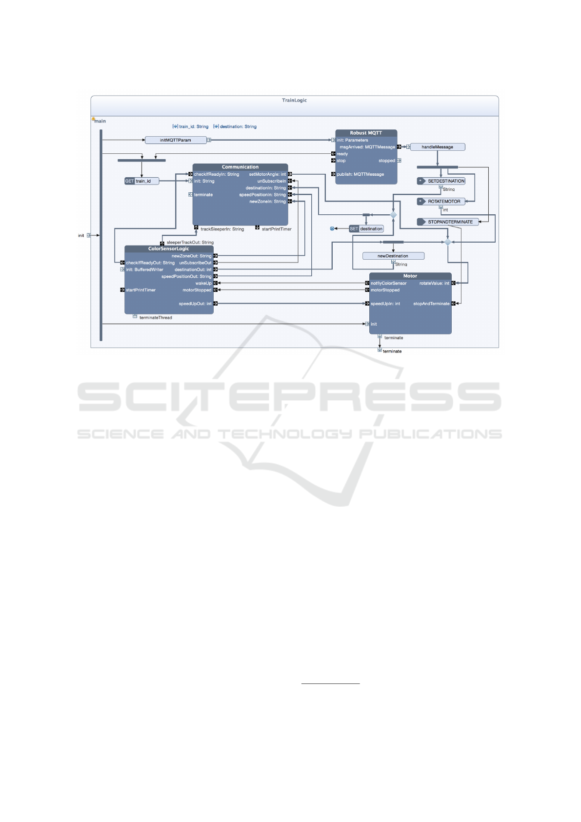
Figure 8: Building block for the train control logic.
the thread handling color changes pauses between two
checks for exactly 14 ms. When it runs without paus-
ing, often white color is falsely read. In addition, we
found out that, in general, blue and green render bet-
ter results than red and yellow. We took these experi-
ments into consideration when deciding which colors
to be used at which points in the layout.
5.3 Methodology Step 3
After getting sufficient knowledge about the kine-
matic behavior of the demonstrator as well as the cor-
rect treatment of the color sensors, we continued with
the creation of the final control logic using Reactive
Blocks. As an example, Fig. 8 depicts the UML ac-
tivity of the building block TrainLogic specifying the
control logic of the train controllers. It contains four
inner building blocks. Block Robust MQTT was taken
from a Reactive Blocks library. It specifies the logic to
handle connections with the MQTT server. Building
block ControlSensorLogic models the access to the
color sensor and the interpretation of the metered col-
ors as described in Sect. 4. Block Motor is based on
work in (Overskeid, 2015) and specifies the control of
the train engine. Finally, building block Communica-
tion defines the cooperation with the responsible zone
controller(s) via MQTT.
The semantics of UML activities resemble Petri
Nets such that we can interpret a control or data flow
as tokens running via the edges to the various vertices
of the activity. The block TrainLogic is started by a
flow through the incoming parameter node
3
init that
is forked into three flows. One flow leaving the fork
leads to the operation initMQTTParam that is a carrier
of a Java method creating an object of type Parame-
ters. This object carries the data needed to start an
MQTT connection. It is forwarded towards pin init
of block Robust MQTT. The other two flows leaving
the fork initiate the blocks Communication and Mo-
tor. The block ControlSensorLogic does not need to
be initialized. It gets active when the motor starts op-
erating.
The other flows of the activity are only sketched.
There are several flows from ControlSensorLogic to
Communication modeling the notification of the zone
controller about the various findings of the color sen-
sor. The control of the train speed by the zone con-
troller is specified as a flow from pin setMotorAngle
of building block Communication that defines the de-
sired speed level as an integer value. This flow is for-
warded to pin rotateValue of block Motor after which
the engine speed is adjusted. Two flows from Motor
to ControlSensorLogic realize that the color sensor is
only operative if the motor turns. Finally, the activ-
ity contains three event receptions used to control the
3
The term parameter node refers to pins at the edge of a
UML activity.
A Methodology for Model-based Development and Safety Analysis of Transport Systems
97

train directly from the central console. They can be
used to set destinations for the train, to manage the
motor directly from the console, and to terminate the
train controller. In the latter case, an event of type
STOPANDTERMINATE leads to block Motor in or-
der to stop the train and to switch off the color sensor
before the building block TrainLogic is terminated by
a flow through parameter node terminate.
The model checker and animator of Reactive
Blocks (Kraemer et al., 2009) proved helpful to check
our controller models for functional correctness. The
built-in model checker verified general functional
properties, e.g., that all flows in a block are consis-
tent to the interface descriptions of both, the ESM of
this block and those of the inner blocks. The anima-
tion feature which allows to highlight flows of a block
that can be executed in a certain state, was used to
analyze our models for problem-specific properties.
For instance, by inspecting all states of building block
TrainLogic (see Fig. 8) we found out that a train con-
troller does only unsubscribe the MQTT connection
with a zone controller if it currently is connected with
two of them. Thus, except for the system start, a train
controller is always connected with at least one zone
controller as long as no MQTT connection breaks.
5.4 Methodology Step 4 (b)
BIGAND(
List(
IMPLIES(TimePoint(1429190484062),
BIGAND(List(OccupyNode(288),
OccupyNode(289), OccupyNode(290),
OccupyNode(291), OccupyNode(292),
OccupyNode(293), OccupyNode(294),
OccupyNode(295), OccupyNode(296),
OccupyNode(297)))),
IMPLIES(TimePoint(1429190483864),
BIGAND(List(OccupyNode(287),
OccupyNode(288), OccupyNode(289),
OccupyNode(290), OccupyNode(291),
OccupyNode(292), OccupyNode(293),
OccupyNode(294), OccupyNode(295),
OccupyNode(296)))),
...
Figure 9: Train data in BeSpaceD.
As stated above, the development of the Re-
active Blocks model is in parts based on work
from (Overskeid, 2015) which did not use the special
building blocks needed to enable an automatic extrac-
tion of the control logic as described in step 4a of the
methodology. Therefore, we decided to use alterna-
tive 4b instead, i.e., we applied BeSpaceD to check
logs of runs observed by executing the control soft-
ware. Since Lego trains are usually not damaged by
crashes, we could not only get runs from pure sim-
ulation but also from running the real trains on the
tracks. In Sect. 4.2, we explained that sleepers form
the basis for describing the locations of trains as well
as breaking distances. Therefore, it seemed natural to
use them also in the BeSpaceD proofs. The simula-
tion resp. operation of the train and zone controllers
lead to formulas as sketched in Fig. 9. A formula
comprises a long list of conjunctions marked by a
BIGAND statement. Each conjuncted element features
an IMPLIES statement describing that a time point im-
plies that a train occupies a certain number of sleepers
on the track.
We used BeSpaceD to check runs of various sce-
narios mostly to guarantee freedom of collisions.
Here, the solvers were used to verify that no sleeper
was occupied by more than one train
4
at any time.
But we could also validate that the results observed
in step 2 of the methodology are consistent with the
observed runs. For instance, the higher complexity
of the final control software did not impact the brak-
ing distances compared with the observed ones (see
Fig. 7). The BeSpaceD proofs did not reveal any per-
formance problems. The longest run comprised 1973
time points that correspond to more than 32 minutes
of operation and afforded the check of 10,000’s of
sleepers. They were checked within 0.3 s each on a
standard 2.8 Ghz Intel Core i5 running MacOS.
5.5 Methodology Step 5
Finally, we got the implementation by automatic gen-
eration of Java code from the Reactive Blocks models
that was exported to the EV3 controllers as executable
.jar files. This procedure could be performed for all
controllers of our system within a few minutes.
6 EXPERIENCE FROM
BUILDING THE
DEMONSTRATOR
Together with general library blocks like timers
or buffers and, in particular, the blocks to handle
MQTT (MQTT.org, 2015), around 55% of the model
had not to be created from scratch but could be reused.
4
The inaccuracy of using sleepers for measurement was
compensated by overapproximating the length of the
trains, i.e., we declared a crash even when only one sleeper
lay between those occupied by two trains.
ENASE 2016 - 11th International Conference on Evaluation of Novel Software Approaches to Software Engineering
98

Albeit we have used Reactive Blocks to build trans-
port system controllers only for a relatively short
time, that is not too far from the reuse rate of 70%
that is usually achieved when creating models in al-
ready well-supported application domains (Kraemer
and Herrmann, 2009).
We were also pleased that the input formulas
for BeSpaceD could be easily generated and proved
within very short time frames. We learned, however,
that the necessity to use certain blocks in order to
create descriptive formulas of the control software as
used in alternative 4a of the methodology, might lead
to practical problems. The engineer likes to be as free
as possible when creating or selecting models in order
to be able to address particular design problems flex-
ibly. Thus, the rigid structure of the blocks needed to
facilitate the creation of the BeSpaceD formulas (Her-
rmann et al., 2016) may be seen as cumbersome. We
need to spend more work in solving this conflict be-
tween easy development and analysis.
7 RELATED WORK
In the past, verification and analysis tools have been
typically studied with respect to the underlying ver-
ification and analysis techniques rather than empha-
sizing the domain. PHAVer (Frehse, 2005) is a tool
that allows the analysis of spatial properties in hybrid-
systems. Another application of formal verification
techniques to train systems is described in (Platzer
and Quesel, 2009). Here, deduction-based verifica-
tion techniques from the KeYmaera system (Platzer
and Quesel, 2008) are applied. An application of the
SPIN model checker for the verification of control
software aspects of a railway system is described in
(Cimatti et al., 1998). A variety of other generic tools,
recent work and approaches, e.g., (Caires and Torres
Vieira, 2012; Cimatti et al., 2015; Tiwari, 2015) for
model checking spatial properties of cyber physical
systems exist. The combination of Reactive Blocks
with BeSpaceD has been studied, e.g., in (Han et al.,
2015; Herrmann et al., 2016). Here, the emphasize is
on robots and either measured or simulated spatiotem-
poral values. Unlike in this paper, the combination of
simulation and measured values was not considered.
The European Rail Traffic Management System
(ERTMS) is a major industrial project undertaken by
the Association of the European Rail Industry mem-
bers. Its main focus is on creating a seamless in-
tegrated railway system in Europe to increase Eu-
ropean railways competitiveness, capacity, reliabil-
ity rates and safety (ERTMS Project, 2015; UNIFE
Project, 2015). A relevant focus is the automatic
train protection system named European Train Con-
trol System (ETCS), and the Global System for Mo-
bile Communications – Railway (GSM-R). GSM-R
is based on the GSM standard and provides voice
and data communication between the track controllers
and the train. It uses frequencies specifically re-
served for railroad applications. A variety of other
large scale European funded projects exists in the do-
main of safety-critical cyber-physical system. For
example, the ARTEMIS Chess (CHESS-Consortium,
2010) project includes a focus on the rail domain.
Among other results, it produced a modeling lan-
guage.
Our work uses a similar lego infrastructure
as (Overskeid, 2015) where new means for pub-
lic transport have been studied based on Lego
Mindstorms and Reactive Blocks. In contrast to
Overskeid’s work, however, ours is more centered on
software quality, in particular, with respect to mak-
ing systems safe. For that, the separation of the con-
trol functionality between train and zone software is
performed in a novel way that disburdens the perfor-
mance of the EV3 controllers better when a larger
number of trains has to be coordinated. Further, the
use of BeSpaceD enables us to verify relevant spa-
tiotemporal properties formally. Finally, following
the methodology presented in Sect. 3 facilitates car-
rying out a well-regulated software engineering pro-
cess.
8 CONCLUSION
We described our methodology that is able to check
safety properties on measured and simulated data col-
lected from a transportation system. A major effort of
the paper is the realization of a demonstrator and the
application of the methodology to the demonstrator,
as well as its evaluation.
Currently, we continue our work by using the in-
troduced methodology for two other projects. The
one is an extension of the train layout such that traf-
fic in both directions will be possible. Further, the
zone controllers shall be replaced by direct collabo-
rations of the train controllers that work together in
order to achieve the spatiotemporal properties. The
other approach will use the methodology for a set of
robots controlled by Raspberry Pies (Upton and Hal-
facree, 2014) that, in addition to not colliding, shall
cooperate in order to, e.g., transport certain pieces to-
gether without letting them fall down. Moreover, we
discuss with Statens Vegvesen, the Norwegian Public
Roads Administration, and Jernbaneverket, the Nor-
wegian Government’s Agency for Railway Services,
A Methodology for Model-based Development and Safety Analysis of Transport Systems
99

how to introduce our research into the development
and licensing process of real transport systems.
Other future work centers on investigating the
use of the introduced platform and methodology
in the context of collaborative engineering (Blech
et al., 2014). In particular, we aim at providing the
BeSpaceD-based safety analysis as a cloud based ser-
vice. We are also working on using analysis results to
provide adequate views to operators and other stake-
holders using devices providing different form fac-
tors. A first practical usage is the remote monitoring
of the Lego Mindstorms demonstrator. For that, sev-
eral methods to visualize the operational state of the
trains are under development.
REFERENCES
Blech, J. O., Peake, I., Schmidt, H., Kande, M., Ra-
maswamy, S., Sudarsan SD., and Narayanan, V.
(2014). Collaborative Engineering through Integra-
tion of Architectural, Social and Spatial Models.
In Emerging Technologies and Factory Automation
(ETFA). IEEE Computer.
Blech, J. O. and Schmidt, H. (2013). Towards Modeling
and Checking the Spatial and Interaction Behavior of
Widely Distributed Systems. In Improving Systems
and Software Engineering Conference.
Blech, J. O. and Schmidt, H. (2014). BeSpaceD: Towards
a Tool Framework and Methodology for the Speci-
fication and Verification of Spatial Behavior of Dis-
tributed Software Component Systems. Technical re-
port, arXiv.org.
Caires, L. and Torres Vieira, H. (2012). SLMC: a tool for
model checking concurrent systems against dynami-
cal spatial logic specifications. In Tools and Algo-
rithms for the Construction and Analysis of Systems,
pages 485–491. Springer-Verlag.
CHESS-Consortium (2010). Chess modeling language and
editor v1. 0.2. March 31, 2010.
Cimatti, A., Giunchiglia, F., Mongardi, G., Romano, D.,
Torielli, F., and Traverso, P. (1998). Model checking
safety critical software with SPIN: an application to a
railway interlocking system. In Computer Safety, Reli-
ability and Security, pages 284–293. Springer-Verlag.
Cimatti, A., Griggio, A., Mover, S., and Tonetta, S. (2015).
HyComp: An SMT-Based Model Checker for Hybrid
Systems. In Tools and Algorithms for the Construc-
tion and Analysis of Systems, pages 52–67. Springer-
Verlag.
ERTMS Project (2015). ERTMS in brief.
http://www.ertms.net/?page id=40. Accessed:
2015-08-14.
Frehse, G. (2005). PHAVer: Algorithmic verification of hy-
brid systems past HyTech. In Hybrid Systems: Com-
putation and Control, pages 258–273. Springer.
Han, F., Blech, J. O., Herrmann, P., and Schmidt, H. (2014).
Towards Verifying Safety Properties of Real-Time
Probability Systems. In 11th International Workshop
on Formal Engineering approaches to Software Com-
ponents and Architectures (FESCA). EPTCS.
Han, F., Blech, J. O., Herrmann, P., and Schmidt, H. (2015).
Model-based Engineering and Analysis of Space-
aware Systems Communicating via IEEE 802.11. In
39th Annual International Computers, Software & Ap-
plications Conference (COMPSAC), pages 638–646.
IEEE Computer.
Han, F., Herrmann, P., and Le, H. (2013). Modeling and
Verifying Real-Time Properties of Reactive Systems.
In 18th International Conference on Engineering of
Complex Computer Systems (ICECCS), pages 14–23.
IEEE Computer.
Herrmann, P., Blech, J. O., Han, F., and Schmidt, H. (2016).
A Model-based Toolchain to Verify Spatial Behavior
of Cyber-Physical Systems. International Journal of
Web Services Research (IJWSR), 13(1):40–52.
Hordvik, S. E. and Øseth, K. (2015). Control Software for
an Autonomous Cyber-Physical Train System. Mas-
ter’s thesis, Norwegian University of Science and
Technology (NTNU).
Kraemer, F. A. and Herrmann, P. (2009). Automated En-
capsulation of UML Activities for Incremental Devel-
opment and Verification. In Model Driven Engineer-
ing Languages and Systems (MoDELS), LNCS 5795,
pages 571–585. Springer-Verlag.
Kraemer, F. A. and Herrmann, P. (2010). Reactive Seman-
tics for Distributed UML Activities. In Joint WG6.1
International Conference (FMOODS) and WG6.1 In-
ternational Conference (FORTE), LNCS 6117, pages
17–31. Springer-Verlag.
Kraemer, F. A., Herrmann, P., and Bræk, R. (2006). Align-
ing UML 2.0 State Machines and Temporal Logic
for the Efficient Execution of Services. In 8th Inter-
national Symposium on Distributed Objects and Ap-
plications (DOA06), LNCS 4276, pages 1614–1632.
Springer-Verlag.
Kraemer, F. A., Sl
˚
atten, V., and Herrmann, P. (2009). Tool
Support for the Rapid Composition, Analysis and Im-
plementation of Reactive Services. Journal of Systems
and Software, 82(12):2068–2080.
Lee, E. (2008). Cyber Physical Systems: Design Chal-
lenges. In Object Oriented Real-Time Distributed
Computing (ISORC), 2008 11th IEEE International
Symposium on, pages 363–369. IEEE Computer.
MQTT.org (2015). Message Queuing Telemetry Transport
(MQTT). http://mqtt.org/. accessed: 2015-08-14.
Overskeid, K. M. (2015). Personal Rapid Transit (PRT)
System using Lego Mindstorms. Master’s thesis,
Norwegian University of Science and Technology
(NTNU).
Platzer, A. and Quesel, J.-D. (2008). KeYmaera: A Hy-
brid Theorem Prover for Hybrid Systems (System De-
scription). In Automated Reasoning, pages 171–178.
Springer.
Platzer, A. and Quesel, J.-D. (2009). European Train Con-
trol System: A Case Study in Formal Verification.
In Formal Methods and Software Engineering, pages
246–265. Springer.
ENASE 2016 - 11th International Conference on Evaluation of Novel Software Approaches to Software Engineering
100

Presburger, M. (1929).
¨
Uber die Vollst
¨
andigkeit eines
gewissen Systems der Arithmetik ganzer Zahlen, in
welchem die Addition als einzige Operation hervor-
tritt. In Comptes rendues du ler Congres des Math.
des Pays Slaves, Warsaw, pages 192–201, 395.
Sl
˚
atten, V., Kraemer, F., and Herrmann, P. (2011). To-
wards Automatic Generation of Formal Specifications
to Validate and Verify Reliable Distributed System:
A Method Exemplified by an Industrial Case Study.
In 10th International Conference on Generative Pro-
gramming and Component Engineering (GPCE’11),
pages 147–156. ACM.
Tiwari, A. (2015). Time-Aware Abstractions in Hybrid-
Sal. In Computer Aided Verification, pages 504–510.
Springer-Verlag.
UNIFE Project (2015). UNIFE. http://www.unife.org/. ac-
cessed: 2015-08-14.
Upton, E. and Halfacree, G. (2014). Raspberry Pi User
Guide. Wiley.
A Methodology for Model-based Development and Safety Analysis of Transport Systems
101
