
A Novel R-UML-B Approach for Modeling and Code Generation of
Reconfigurable Control Systems
Raja Oueslati
1,2
, Olfa Mosbahi
1
, Mohamed Khalgui
3,1
and Samir Ben Ahmed
2
1
LISI, National Institute of Applied Sciences and Technology, INSAT, University of Carthage, Tunis, Tunisia
2
Faculty of Sciences, FST, University of Tunis El Manar, Tunis, Tunisia
3
Xidian University, Xi’an, China
Keywords:
Reconfigurable Control System, B Method, Modeling, UML, Code Generation.
Abstract:
This research paper deals with the modeling and code generation of Reconfigurable Control Systems (RCS)
following UML and B methods. Reconfiguration means dynamic changes of the system behavior at run-time
according to well-defined conditions to adapt it to its environment. A reconfiguration scenario is applied as a
response to user requirements or any possible evolution in its environment. We affect a Reconfiguration Agent
(RA) to RCS to apply an automatic reconfiguration. A new approach called (R-UML-B) is proposed. It consists
of three complementary phases: UML specification, B specification and the simulation phase. The first phase
models the RCS following UML class and state diagrams. The second phase translates UML specification into
B specification according to the well-defined rules and R-UML-B formalism to define the Behavior, Control,
Listener, Database and Executive modules of the RCS. Then, we determine the refinement model and the code
generation of the B abstract model in C code. We verify the RCS by following the B method in order to
guarantee the consistency and the correctness of the specification, refinement and code generation levels. The
third phase imports the generated C code to implement a simulator, named B Simulator in order to test and
validate the proposed approach. All the contributions of this work are applied to the benchmark production
system EnAS.
1 INTRODUCTION
Control Systems (CS) are designed to perform func-
tions in order to control a physical process in the real
world such as automotive, avionics and industrial au-
tomation. These systems often have real-time com-
puting constraints. Due to the trade-off between per-
formance and rapid response to market changes and
customer needs, the requirements in industrial CS are
increasingly growing in terms of flexibility and agility
(Theiss et al., 2009). In this context, one of the most
promising directions to address these issues is the re-
configuration of CS. The reconfiguration consists in
switching the system from its current configuration
to another one at runtime by applying a reconfigura-
tion scenario. We distinguish two types of reconfigu-
rations: static (off-line) and dynamic (on-line) (An-
gelov et al., 2005). The former is applied off-line
before system
′
s cold start, whereas the latter is ap-
plied automatically at run-time. In the latter case, two
types exist : manual reconfigurations to be executed
by users and automatic (intelligent) reconfigurations
to be performed by intelligent agents that can be a
physical resource (robot, machine ...) or a logical re-
source (scheduler), and hybrid reconfigurations which
are the combination of manual and automatic recon-
figurations.
On the other hand, B is a formal software devel-
opment method that covers software process from the
abstract specification to the executable implementa-
tion. Moreover, it has been used successfully in ma-
jor safety critical systems such as the automatic train
operating system for METEOR, a driverless metro in
the city of Paris (Behem et al., 1999), medical sys-
tems (M´ery and Singh, 2013) and electronic voting
machines (Cansell et al., 2007). Also, a strong point
of B is to have robust and useful tools to support the
specification, design, proof, and code generation like
Atelier B or B4free.
In a previous work (Oueslati et al., 2014), we have
proposed the new formalism called R-B to model
RCS following the B method. The formalism R-B
consists of two modules: Behavior and Control. The
first module is the union of all system configurations
140
Oueslati, R., Mosbahi, O., Khalgui, M. and Ahmed, S.
A Novel R-UML-B Approach for Modeling and Code Generation of Reconfigurable Control Systems.
In Proceedings of the 11th International Conference on Evaluation of Novel Software Approaches to Software Engineering (ENASE 2016), pages 140-147
ISBN: 978-989-758-189-2
Copyright
c
2016 by SCITEPRESS – Science and Technology Publications, Lda. All rights reserved
where each one is represented by a B machine M
i
.
The second module is formed by a set of reconfigura-
tion functions handling automatic transformations be-
tween specific configurations in the behavior module
after receiving reconfiguration requests to adapt the
system to environment changes. When we applied a
reconfiguration scenario, a reconfiguration function is
executed to switch the system behavior from one con-
figuration to another one at run-time, including the
addition /removal of operations from a source M
i
, to
obtain a target M
j
machine. To avoid redundant cal-
culations, we implemented a prototyped tool called
Check R-B. This prototype can be added to B4free
tool as a module to solve the redundancy problem of
different behaviors sharing similar operations. The
proposed solution allows us to implement automati-
cally the code generation of the RA after the refine-
ment of the B abstract machines. However, as a for-
mal method, B cannot avoid inconsistencies and in-
accuracies in specification. As cited in many research
works (Meyer and Souqui`eres, 1999)(Nguyen, 1998),
a combination of semi-formal and formal methods
can contribute to a better specification of software en-
gineering method. For this objective we propose to
integrate the unified modelling language UML in the
proposed development approach of RCS to borrow
features from the two classes of specification, for-
mal and semi-formal ones. Each method has been
proved to be useful in the development of CS. For-
mal methods are based on mathematical notations and
axiomatic which induce verification and validation.
Furthermore, semi-formal methods are graphic, struc-
tural and user-friendly. Each method is applied on a
suitable case study, that we regret some missing fea-
tures we could find in the other class. This remark has
motivated our work. We are interested in the integra-
tion of formal and semi-formal methods in order to
lay out a specification approach which combines the
advantages of theses two classes.
To deal with the modeling and the code generation
of dynamic reconfiguration of CS, we affect an RA to
RCS to apply automatic reconfigurations. We offer in
this work a new approach called R-UML-B method
allowing the development of RCS from specification
to code generation. We propose in this paper a devel-
opment process which consists of three complemen-
tary phases in order to develop such systems: 1. UML
specification, 2. B specification and 3. simulation
phase. The first phase allows us to model the RCS
following UML class and state diagrams. The second
phase translates UML specification into B specifica-
tion according to the well-defined rules and R-UML-
B formalism to define the Behavior, Control, Listener,
Database and Executive modules of the RCS. Then,
Abstract Model
Refinement Model
Source Code (C, Ada)
Code Generation
Code Generation Step
Requirements Specification
Specification Step
Refinement Step
Refinement
Translation
Abstract specification
Informal specification
Refinement 1
Refinement n
Refinement Proof Obligations
Refinement
Refinement Proof Obligations
Refinement Proof Obligations
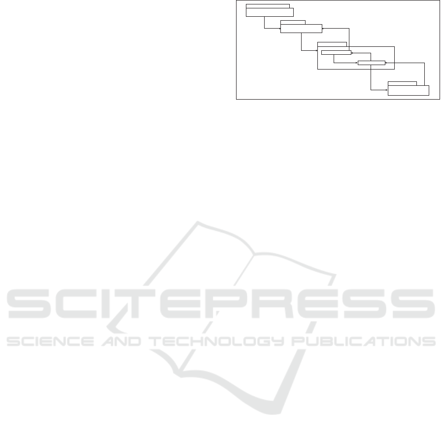
Figure 1: B Method.
we determine the refinement model and the code gen-
eration of the B abstract model in C code. The third
phase is for importing the generated code to develop
a simulator with a suitable tool in order to validate
our approach. The proposed approach is the first to
our knowledge to deal with the modeling and the code
generation of RCS following UML and B methods.
The rest of the paper is organized as follows: in
Section 2, we present the background in which we
introduce B method, transformation rules from UML
diagrams into B models and an overview about the
implementation of RCS. In Section 3, we present the
proposed approach R-UML-B to model and generate
the code of RCS. In Section 4, we apply all contri-
butions of this work to the case study EnAS. We fin-
ish by a conclusion and the exposition of our future
works.
2 BACKGROUND KNOWLEDGE
In this section, we present an overviewon well-known
B method, transformation rules from UML to B spec-
ification and an overview about the implementation of
RCS.
2.1 B Method
We present in this subsection, the well-known B
method. B is a formal method developed by Abrial
(Abrial, 1996). It covers all the aspects in the soft-
ware development of a system: Specification, Refine-
ment and Code generation, as shown in Figure 1. It
integrates set theory, logic predicate and generalized
substitution language. The B method has a robust and
useful tool Atelier B to support the specification, de-
sign, proof and code generation.
2.1.1 Specification Step
The specification step consists in translating the soft-
ware requirement into an abstract model in B. The B
method is based on the notion of abstract machine
A Novel R-UML-B Approach for Modeling and Code Generation of Reconfigurable Control Systems
141

that is composed of three parts: (i) Header part de-
scribes by means of the clauses MACHINE and CON-
STRAINTS, (i) Static part describes by means of the
clauses SETS, CONSTANTS, PROPERTIES, VARI-
ABLES and INVARIANT and (iii) Dynamic part de-
scribes by means of the clauses INITIALISATION and
OPERATIONS.This model is finished when all the re-
quirements are described in the model.
2.1.2 Refinement Step
The following step consists in refining the abstract
model of a software system into another mathemat-
ical model that is more concrete. This model is fin-
ished when all the components of the abstract model
are refined into components that can be automatically
translated into C code.
2.1.3 Code Generation Step
The Atelier B tool translates automatically all the im-
plementations of the concrete model into C code.
2.1.4 Composition in B
Abstract machines can be combined, through the
clauses INCLUDES and USES to build new specifica-
tions (Abrial, 1996). The clause INCLUDES allows a
machine to be included in another one with read/write
access. A machine M includes a machine M1 means
that M has a full access to the constants, sets, vari-
ables and operations of M1 and operations of M can
be defined by using any M1 operations. The clause
USES allows a machine to be shared by another one
with read only access. A machine M2 uses a machine
M3, M2 can only make use of the static part of M3.
2.2 Transformation Rules from UML to
B
The authors in (Meyer and Souqui`eres, 1999)
(Nguyen, 1998) have proposed the transformation
rules from UML semi-formal specification to B for-
mal specification. In what follows, we present the im-
portant ones.
• From UML Class Diagram to B Specification:
Each class is expressed by an abstract machine
Class
i
that describes a deferred set CLASS
i
of the
possible instances of the class Class
i
. The set of
existing instances is modelled by a variable class
i
constrained to be a subset of CLASS
i
. For each
attribute Attr
i
, a variable attr
i
is created and de-
fined in the INVARIANT clause as a binary rela-
tion between the set class
i
and its associated type
Type
attr
. The Ass
ij
association between classes is
formalised by adding a variable ass
ij
and a prop-
erty of invariance defining it as a binary relation
between class
i
and class
j
.
• From UML State Diagram to B Specification:
For each diagram associated to the class Class
i
,
we create an enumerated set STATE
i
which gath-
ers all the states of the diagram. The state of an
object is recorded by a variable state
i
defined as
a function from the set class
i
of the existing in-
stances of Class
i
to STATE
i
. Each event is for-
malized by an operation which is parameterized
by the target objects and the eventual parameters
of the event. Parameters are typed by a predicate
in the precondition of the operation. The opera-
tion is defined by a SELECT substitution which
has as many cases as transitions where the event
appears. The operation modifies the state of the
object and calls the operations associated to ac-
tions and events specified in the transition.
2.3 Implementation of Reconfigurable
Systems
Nowadays, important research works have been pro-
posed to dvelop RCS. (Krichen et al., 2015) pro-
pose a model-driven engineering based approach to
design reconfigurable distributed real-time embedded
systems (DRES) with execution framework support.
Their approach leads the designer to specify step by
step the system from one abstract model to a con-
crete one. This target model is related to a specific
platform leading to the generation of the most part of
the system implementation. They also develop a new
middleware that supports reconfigurable DRES. The
work of (Gogniat et al., 2010) deals with the design of
self-reconfigurable multiprocessor systems on chip.
To provide a comprehensive approach, the authors
address three major points : i) definition of an effi-
cient architectural model with adapted API in order to
help designer during the design steps, ii) a bitstreams
repository hierarchy to face potential huge number of
bitstreams which will be required for future versatile
systems and iii) a complete design methodology start-
ing from a high level of specification (UML). Increas-
ing modeling abstraction levels allows to hide imple-
mentation details to the designer, leaving focus on
system requirements rather than implementation is-
sues.
The contribution that we propose in the current pa-
per is original since it addresses the modeling and the
code generation of RCS following UML and B meth-
ods. To our knowledge, this is the first contribution
addressing this problem.
ENASE 2016 - 11th International Conference on Evaluation of Novel Software Approaches to Software Engineering
142
UML Specification
1
B Specification
2
Abstract Model
Code Generation
Refinement Model
3
Transformation rules from UML to B
R-UML-B Formalism
Simulation Phase
Behavior Module
Listener Module
Database Module
Executive Module
Control Module
State Diagram
Behavior Module
Listener Module
Database Module
Executive Module
Control Module
Class Diagram
C CodeB Simulator
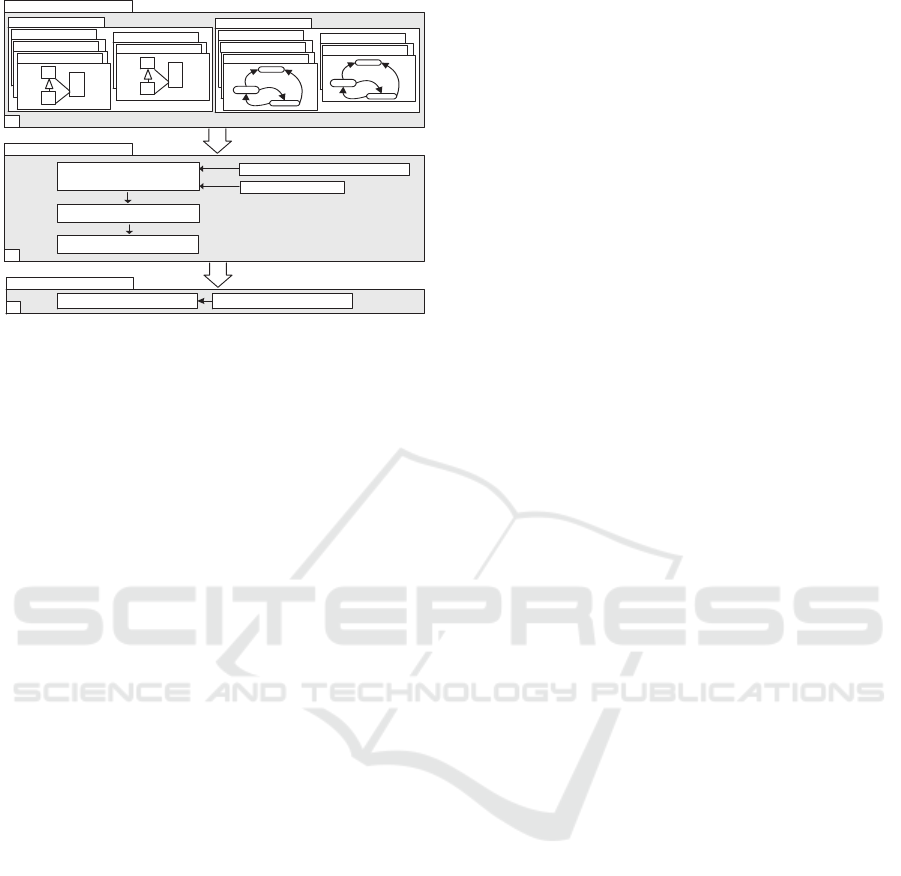
Figure 2: R-UML-B Approach.
3 R-UML-B APPROACH
In this section, we present the proposed R-UML-B
approach for modeling and generation code of RCS.
Then, we define the proposed UML-DR-B formalism.
3.1 Presentation of R-UML-B Approach
To offer more flexibility to the execution of recon-
figuration scenarios on RCS, we define an intelligent
Reconfiguration Agent called RA which checks the
environment
′
s evolution to adapt the system. The role
of an RA is to apply an automatic reconfiguration on
the CS. Our goal is to model and generate the intel-
ligent RA code of an RCS. In this context, we define
an R-UML-B approach to design an RA that defines
a development process from models to code as shown
in Figure 2. This process consists of three phases to
be followed by the user:
1. UML Specification: modeling of the RCS fol-
lowing the UML class and state diagrams. It con-
sists of five modules: Behavior, Control, Listener,
Database and Executive. The behavior module
defines all possible behaviors of the system. The
control module is a set of reconfiguration func-
tions applied to change the system from a be-
havioral configuration to another one at run-time
when a reconfiguration scenario is applied as a re-
sponse to user requirements or any possible evolu-
tion in its environment. The Listener module de-
tects all events that trigger reconfiguration scenar-
ios. The database module contains architecture,
composition, data and comparative information of
the RCS. The Executive module adds or removes
the appropriate operations to respond to reconfig-
uration requests and to switch between the spe-
cific configurations at run-time,
2. B Specification: is composed of three steps as
following:
a. Abstract Model: using of the transformation
rules defined previously and the R-UML-B for-
malism to obtain B abstract machines from UML
diagrams,
b. Refinement Model: refining the abstract
model into another model more concrete,
c. Generation Code: translating automatically
all the implementations of the refinement model
into C code using the Atelier B tool,
3. Simulation Phase: importation of the generated
code to develop a simulator with a suitable tool
called B Simulator.
3.2 R-UML-B Formalism
In this subsection, we define the R-UML-B formalism
to model RCS. It defines the behavior β, the control
R, the Listener Listener, the Database Database and
Executive Executive modules.
Definition 1. R-UML-B. An R-UML-B formalism is
a structure defined as follows:
R-UML-B = (β, R, Listener, Database, Executive)
where: (i) β is the behavior module, (ii) R is the con-
trol module, (iii) Listener is the listener module, (vi)
Database is the database module and (v) Executive is
the executive module of the RCS.
Definition 2. Behavior Module. The Behavior Mod-
ule β is the union of m configurations of the RCS.
Each Behavior Module class of UML class diagram
is expressed by an abstract machine presented as fol-
lows:
β = {M
class
1
, M
class
2
, ..., M
class
i
, ..., M
class
m
}
Definition 3. Control Module. The Control Mod-
ule R is a set of reconfiguration functions allowing
automatic transformations between configurations. A
reconfiguration function r
(x,x
′
)
is a structure chang-
ing the system from a configuration x to another
one x’ defined as follows r
(x,x
′
)
= (Cond
(x,x
′
)
, S
(x,x
′
)
),
where: (i) Cond
(x,x
′
)
∈{True, False}:the pre-condition
of r
(x,x
′
)
, (ii) S
(x,x
′
)
:(
•
M) →(M
•
) is the structure mod-
ification instruction where (
•
M) denotes the machine
M
classi
before the application of r
(x,x
′
)
and (M
•
) de-
notes the target machine M
classj
after the reconfigu-
ration function r
(x,x
′
)
is applied. The structure S
(x,x
′
)
models the transformation from a M
classi
to another
M
classj
machine when we apply a reconfiguration sce-
nario. If Cond
(x,x
′
)
= True, r
(x,x
′
)
is executable, other-
wise it cannot be executed. The structure modification
instruction S
(x,x
′
)
guides the system transformation
from (
•
M) to (M
•
), including the addition /removal
of operations from a source M
classi
, to obtain a target
A Novel R-UML-B Approach for Modeling and Code Generation of Reconfigurable Control Systems
143

M
classj
machine. The pre-condition of a reconfigura-
tion function means specific external instructions and
gusty functioning failures.
Definition 4. Listener Module. The Listener Mod-
ule called Listener is responsible for receiving the re-
configuration requests while the system is executing
other functions. The occurrence of a request does not
require the stopping of the system. This module is a
set of external and internal events that trigger recon-
figuration scenarios represented as follows:
Listener = (Event
external
, Event
internal
)
Where: Event
external
depicts the user requests that
occur to change the system production mode and
Event
internal
represents the system errors. The Lis-
tener is modeled by UML class and translated into B
machine M
Listener
thanks to transformation rules from
UML to B.
Definition 5. Database Module. The Database Mod-
ule called Database is a set of data having the follow-
ing structure:
Database=(Architecture, Composition, Data,
Comparative)
Where (i) Architecture represents the architectural re-
configuration level that defines the different system
′
s
architecture when particular conditions are met, (ii)
Composition represents the composition reconfigura-
tion level that changes the composition of operations
for a given architecture, (iii) Data represents the data
reconfiguration level that changes the values of vari-
ables without changing the system operations and (vi)
Comparative compares configuration system before
and after applying reconfiguration scenario to deter-
mine the processes to be used and their execution or-
der. The Database Module is modeled by UML class
diagram and translated into B machine M
Database
.
Definition 6. Executive Module. The Executive
Module called Executive is a set of operations of the
behavior x and those of the behavior x’, represented
as follows:
Executive = (∪op
iMclassi
, ∪op
iMclassj
)
Where: ∪op
iMclassi
denotes the machine operations of
M
classi
before the application of r
(x,x
′
)
and ∪op
iMclassj
denotes the target machine operations of M
classj
. The
Executive adds /removes operations from a source
M
classi
to obtain a target M
classj
machine. The Exec-
utive Module is modeled by UML class diagram and
translated into B machine M
Executive
.
Definition 7. B Machine. A B machine M
i
is the
machine represented by the following tuple:
M
i
= (C, S, Const, P, V, I, Init, Op)
Where: (i) C: the system constraints, (ii) S: the sets,
(iii) Const: the constants, (iv) P: the properties con-
stants , (v) V: the variables, (vi) I: the invariants, (vii)
Init: the initialization of variables and (viii) Op: the
operations. All the components of the B machine are
deducted from UML class and state diagrams accord-
ing to the transformation rules from UML into B.
4 CASE STUDY:
RECONFIGURATION OF
INDUSTRIAL SYSTEM EnAS
In order to explain our contribution, we present in
this section our demonstrator benchmark production
system EnAS available at Martin Luther University
in Germany. It is served for research and education
purposes in many universities. Then, we apply our
approach to the case study.
4.1 EnAS System
EnAS transports workpieces from the benchmark pro-
duction system FESTO into storing stations. The
workpieces shall be placed inside tins to close with
caps afterwards. The EnAS system is mainly com-
posed of a belt, two jack stations (J1 and J2) and
two gripper stations (G1 and G2). The Jack sta-
tions place new drilled workpieces from FESTO and
close tins with caps, whereas the gripper stations re-
move charged tins from the belt into storing stations
(ST1 and ST2). Initially, the belt moves a particular
pallet containing a tin and a cap into the first jack
station J1. Four production modes are assumed in
this paper to be applied in EnAS, depending on the
number of drilled workpieces nbpieces, tins and caps
nb(tins+caps), as follows:
• Policy1: If nbpieces/nb(tins+caps) <C1, then J1
places and closes, G1 removes into St1,
• Policy2: If nbpieces/nb(tins+caps) ≥C1, then J1
places, J2 closes, G2 removes into St2,
• Policy3: If C1≤nbpieces/nb(tins+caps)<C2,
then J1 places and closes, G2 removes into St2
or J1 places, J2 closes, G1 removes into St1,
• Policy4: If nbpieces/nb(tins+caps)≥ C2, then J1
places, J2 places and closes, G2 removes the tin
(with two pieces) into St2.
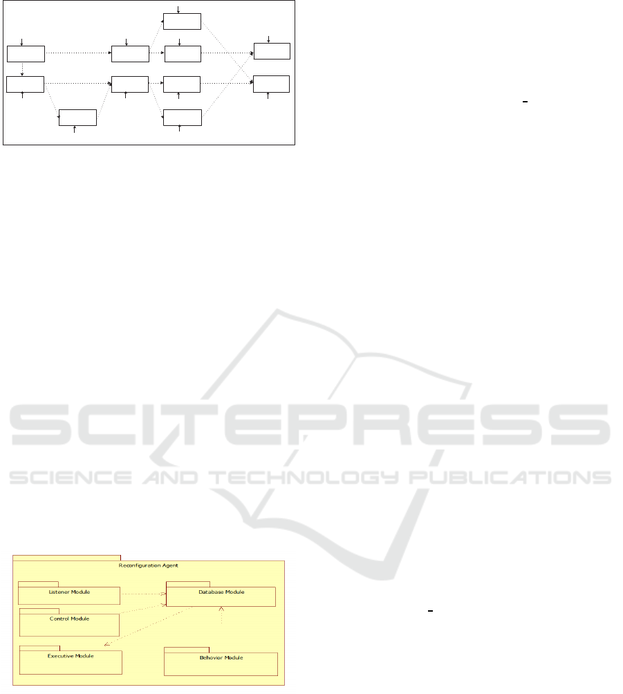
The operating of EnAS system, as explained in Fig-
ure 3, is represented by five behaviors, presented as
follows:
B1
∆
= op1 ; op2 ; op3 ; op4 ( Policy1 default initial
production mode)
B2
∆
= op1 ; op6 ; op8 ; op10 ; op11 ( Policy2)
B3
∆
= op1 ; op2 ; op5 ; op11 ( Policy3)
ENASE 2016 - 11th International Conference on Evaluation of Novel Software Approaches to Software Engineering
144
J1 places
workpiece
op1:place1
J1 closes tin/
cap
op2:close1
Belet moves
tin from J1 to
G1
op3:move1
G1 removes
tin to ST1
op4:remove1
Belet moves
workpiece to
J2
op6:move3
J2 closes tin/
cap
op8:close2
Belet moves
tin from J2 to
G2
op10:move2
G2 removes
tin to ST2
op11:remove2
J2 places
workpiece
op7:place2
Belet moves
tin from J2 to
G1
op9:move5
Belet moves
tin from J1 to
G2
op5:move4
Figure 3: Working process of EnAS.
B4
∆
= op1 ; op6 ; op8 ; op9; op4 ( Policy3)
B5
∆
= op1 ; op6 ; op7; op8 ; op10; op11 ( Policy4)
The system is completely stopped if both J1 and J2
are broken. We should make EnAS able to switch
policies automatically at run-time according to any
changes in working environment caused by errors or
user requirements without a halt. It is assumed that
policies are interchangeable.
4.2 R-UML-B Approach Application:
UML Specification Phase
We illustrate in this subsection UML class and state
diagrams to model the RA affected to EnAS system.
4.2.1 UML Class Diagram
The conceptual model comprises five modules to be
organized into a set of packages as explained in Fig-
ure 4: Behavior, Control, Listener, Database and Ex-
ecutive.
Figure 4: Reconfiguration Agent: UML Package Diagram.
These components interact and collaborate together
in order to monitor the system evolution, to react to
reconfiguration requests and to maintain the effective
functioning of the RCS. Our system detects and clas-
sifies the occurred events and looks for finding the
suitable reconfiguration scenario to apply at run-time
without a halt. We detail in the following these five
modules, as shown in Figure 5.
• Listener Module: represents all the events that
can disrupt the system functioning and caused by
system errors or user requirements. When the Lis-
tener detects and classifies the reconfiguration re-
quests, then they will be sent to be treated by the
database. It is modeled by Listener superclass and
two subclasses: Error and User Request,
• Database Module: plays a very important role in
the reconfiguration approach. The Database su-
perclass manages all the interactions in the sys-
tem, related to the Architecture, Composition,
Data and Comparative subclasses. When the
Database receives the reconfiguration request, it
searches for the suitable reconfiguration scenario.
Firstly, it looks for the new architecture to which
the system will switch according to the Architec-
ture subclass. Then, it determines the composition
of the new system architecture from the Compo-
sition subclass. After, it determines the new value
of the changed variable from the Data subclass.
Finally, it compares the composition of the old ar-
chitecture with the new one according to Compar-
ative subclass in order to determine the processes
that will be kept, those that will be removed and
those that will be added as well as their execution
order. Once the response to the reconfiguration re-
quest is provided by the Database, it will be sent
to the Executive,
• Control Module: presents by Control class. It
includes all possible reconfiguration functions of
the system. Each reconfiguration function has a
pre-condition and a structure modification instruc-
tion,
• Executive Module: modeled by Executive class.
It represents the processes that will be added or re-
moved when a reconfiguration scenario is applied.
All changes made to our system will be recorded
in the Journal
File association class. When, the
Database sends the reconfiguration request re-
sponse, the Executive reacts by adding and re-
moving the associated processes.
• Behavior Module: represents all the behaviors of
the EnAS system. It is modeled by Behavior su-
perclass and five subclasses that describe the be-
haviors of the EnAS case study. This module pro-
vides the Database Module of all the system be-
haviors, so that it can determine the different sys-
tem processes.
4.2.2 State Diagram
The EnAS RA Control state diagram as shown in Fig-
ure 6 is composed of five states B1, B2, B3, B4 and B5
A Novel R-UML-B Approach for Modeling and Code Generation of Reconfigurable Control Systems
145
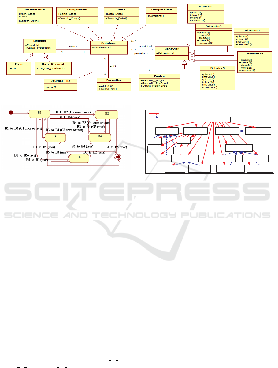
Figure 5: EnAS Reconfiguration Agent: UML Class diagram.
Figure 6: EnAS RA Control Module: State Diagram.
corresponding to the five behaviors which describe
the EnAS system. A set of transition represents the
switching between behaviors according to any change
environment caused by errors or user requirements.
4.3 R-UML-B Approach Application: B
Specification Phase
Once the UML specification phase is established, we
can deduce the B abstract model using the well de-
fined rules and the R-UML-B formalism from EnAS
RA UML diagrams. We present in the following the
EnAS RA which consists of seventeen machines and
the links between them are presented in Figure 7. We
present in the following some ones:
• Behavior.mch machine represents the superclass
of the inheritance hierarchy. It models the objects
of Behavior class and defines the add and remove
operations of class instances,
• B1.mch machine simulates B1 subclass and uses
Behavior.mch machine. It defines the operations
place1(), close1(), move1 () and remove1(),
• Control.mch machine simulates Control
class and defines the operations (B1
to B2(),
B1
to B3(), ..., B5 to B4()) which represent the
transitions of the Control module UML state
machine (see Figure 6),
Error.mch User_Request
Listener.mch
Behavior.mch
B1.mch
B2.mch
B5.mch
B4.mch
B3.mch
Composition.mch Data.mch
Architecture.mch Execution.mch
Database.mch
Control.mch Executive.mch Journal_File.mch
RA.mch
Includes
uses
Figure 7: EnAS RA: B abstract specification structure.
• RA.mch machine represents the EnAS RA which
provides an interface to operations and associa-
tions between classes.
Once the abstract model is complete and validated.
The next step consists in refining RA.mch machine
into a concrete one. Finally, we generate automati-
cally the C code by Atelier B tool. The proof obliga-
tions of B machines were proved by the Atelier B and
all invariants were preserved by operations.
4.4 R-UML-B Approach Application:
Simulation Phase
The last phase of R-UML-B approach is to import the
generated C code obtained in the second phase in or-
der to developa simulator. In fact, to test, validate and
evaluate our approach, we have developed a complete
tool B Simulator by using Qt Creator 2.4.1. It allows
the following services: (i) simulation of EnAS which
performs four policies (Policy1, Policy2, Policy3 and
Policy4), composed of two jack stations (J1 and J2),
two gripper stations (G1 and G2) and two stored units,
(ii) checking operating conditions to detect, identify
and classify reconfiguration requests, eventually, oc-
curred in the EnAS system, (iii) searching for suitable
solutions to reconfigure the CS and (iv) execution the
ENASE 2016 - 11th International Conference on Evaluation of Novel Software Approaches to Software Engineering
146
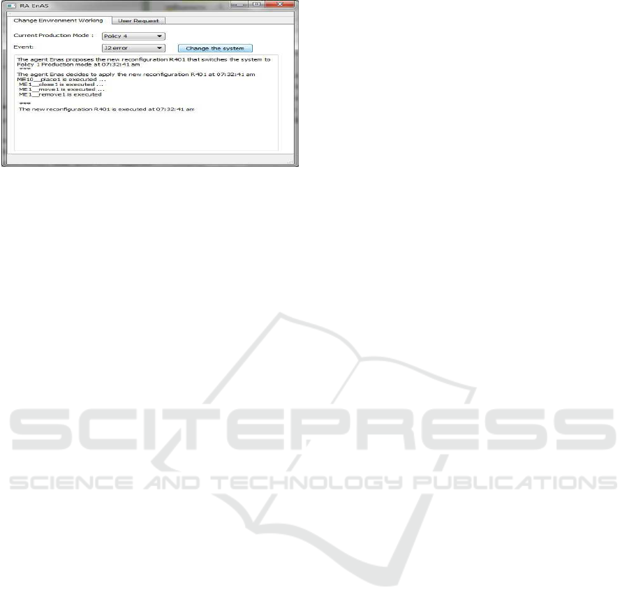
Figure 8: Example of the Reconfiguration Agent.
proposed reconfiguration at run-time. The proposed
tool offers two different graphic interfaces: the first
allows us the possibility to define the actual policy of
the system and the error that causes the reconfigura-
tion. The second one serves to indicate the actual pol-
icy of the system and the target policy the user wants
to attend.
Running Example. Let us assume that EnAS is
in Policy4 production mode when J2 jack station
fails (see Figure 8). Consequently, the EnAS
′
s agent
should decrease the production by sending a request
to the Database Module in order to look for the most
convenient and feasible Policy which is Policy1. The
Executive Module receives the processes that will be
added and those that will be removed to switch the
system from Policy4 to Policy1 and applies the new
reconfiguration.
5 CONCLUSION AND FUTURE
WORK
In this paper, we have proposed an original approach
called R-UML-B for modeling and code generation of
the RCS. It consists of three complementary phases:
UML specification, B specification and simulation
phase. We developed a tool named B Simulator to
simulate the RA. The paper
′
s contributions are ap-
plied to the benchmark production system EnAS.
Different directions can be mentioned as further
work. First of all, we plan to model and to generate
the C code of distributed multi-agent reconfigurable
control systems following the UML and B methods.
We plan also to develop a graphical tool that allows
their simulation.
REFERENCES
Abrial, J.-R. (1996). The B-Book. Cambridge University
Press.
Angelov, C., Sierszecki, K., and Marian, N. (2005). De-
sign models for reusable and reconfigurable state ma-
chines. In the proceedings of the 3th International
Conference on Embedded and Ubiquitous Computing
EUC, pages 152–163, Japan.
Behem, P., Benoit, P., and Meynadier, J. (1999). M´et´eor: A
successful application of b in a large project. In the
proceedings of World Congress on Formal Methods
in the Development of Computing Systems FM, pages
369–387, France.
Cansell, D., Gibson, J., and M´ery, D. (2007). Refine-
ment: A constructive approach to formal software de-
sign for a secure e-voting interface. In the Journal
of Electronic Notes in Theoretical Computer Science,
183(3):39–55.
Gogniat, G., Vidal, J., Ye, L., Crenne, J., Guillet, S.,
De Lamotte, F., Diguet, J.-P., and Bomel, P. (2010).
Self-reconfigurable embedded systems: From model-
ing to implementation. In the proceedings of the In-
ternational Conference on Engineering of Reconfig-
urable Systems and Algorithms ERSA, pages 84–96,
USA.
Krichen, F., Hamid, B., Zalila, B., Jmaiel, M., and Coulette,
B. (2015). Development of reconfigurable distributed
embedded systems with a model-driven approach.
Concurrency and Computation: Practice and Expe-
rience, 27(6):1391–1411.
M´ery, D. and Singh, N. (2013). Formal specifica-
tion of medical systems by proof-based refinement.
ACM Transactions in Embedded Computing Systems,
12(1):15.
Meyer, E. and Souqui`eres, J. (1999). A systematic approach
to transform omt diagrams to a b specification. In the
proceedings of World Congress on Formal Methods
in the Development of Computing Systems FM, pages
875–895, France.
Nguyen, H. (d´ecembre 1998). D´erivation de Sp´ecifications
Formelles B `a partir de Sp´ecifications Semi-formelles.
PhD thesis, Conservatoire National des Arts et
M´etiers - CEDRIC, Paris.
Oueslati, R., Mosbahi, O., Khalgui, M., and Ben Ahmed,
S. (2014). New solutions for modeling and verifi-
cation of b-based reconfigurable control systems. In
the proceedings of the 11th International Conference
on Informatics in Control, Automation and Robotics
ICINCO, pages 749–757, Austria.
Theiss, S., Vasyutynsky, V., and Kabitzsch, K. (2009). Soft-
ware agents in industry: A customized framework in
theory and praxis. IEEE Transactions on Industrial
Informatics, 5(2):563–577.
A Novel R-UML-B Approach for Modeling and Code Generation of Reconfigurable Control Systems
147
