
Ensuring the Comfort in the Heated Space by Controlling the
Temperature in the Heating Installation of a Non-residential Building
Daniel Popescu
1
and Ioan Borza
2
1
Department of Electrical Engineering in Civil Engineering and Building Services,
Technical University of Civil Engineering Bucarest, Bucarest, Romania
2
Department of Civil Engineering and Building Services, Politehnica University of Timisoara, Timisoara, Romania
Keywords: Temperature Control, Nonlinear Control Systems, Modelling, Simulation, Building Automation,
Civil Engineering.
Abstract: In this article is modeled, with the help of Simulink, the automatic system that controls the thermal agent
temperature in a non-residential building chosen for study. It describes how the model has been drawn for the
subsystem entitled HEATED SPACE in the building. There were used mathematical relationships which show
how the indoor temperature is changing, depending on the heat input in building and the heat loss through
building envelope. The other subsystems have been modeled in the articles specified in the bibliography. By
simulation of the model for the automatic system is determinated his behavior during two days in the winter
season. The evaluation of the thermal comfort in the heated space from the building, ensured by using the
automatic system, is made by analyzing the graphs of the significant temperatures from the modeled system:
indoor temperature, outdoor temperature and thermal agent temperature in the heating installation. At the end
of the article are shown the main causes of low thermal comfort in the building, and also the reasons why this
type of automatic system is preferred in many non-residential buildings.
1 INTRODUCTION
The comfort is defined in the Oxford Dictionaries as
being „a state of physical ease and freedom from pain
or constraint”. The comfort can be of several types:
thermal comfort, visual comfort, acoustic comfort,
olfactory comfort.
The quality of the built space in a building depends,
among others, on the thermal comfort in building
(Clements-Croome, 2011; Oancea and Caluianu, 2012;
Frontczak et al., 2012). It can be evaluated using the
indoor temperature perceived by the occupants of the
building. This temperature can be maintained at the
desired constant value only if is kept the balance
between the input heat into the building and the lost
heat through the building envelope.
The thermal comfort in building can be ensured
only by using adequate automatic control systems for
the heating installations.
In the case of automated systems commonly used
in non-residential buildings there is no setpoint for the
indoor temperature, because the indoor temperature is
not controlled with an own control loop. It is used
only the setpoint for flow temperature of the heating
installation. This setpoint value can be established
using the heating curve by selecting the gradient of
circuit with valve, in correlation with the destination
and the constructive characteristics of the heated
building (Mira, 2010; Ilina, 2010).
The current systems used to automate heating
installations in buildings are provided with various
functions that improve the thermal comfort, save
energy and protect the building against frost during
periods when the building is unoccupied (Diematic,
2015). These functions are:
adapting the time response of the systems to the
building inertia factor;
time programming of the heating installation in
comfort period and reduced period;
choosing the room temperature that activates the
antifreeze function;
choosing the outside temperature required for
heating shut-off.
2 OBJECTIVES OF THE
ARTICLE
The objectives are the following:
462
Popescu, D. and Borza, I.
Ensuring the Comfort in the Heated Space by Controlling the Temperature in the Heating Installation of a Non-residential Building.
In Proceedings of the 5th International Conference on Smart Cities and Green ICT Systems (SMARTGREENS 2016), pages 462-467
ISBN: 978-989-758-184-7
Copyright
c
2016 by SCITEPRESS – Science and Technology Publications, Lda. All rights reserved

- modeling the automatic heating system of the
non-residential building so that the model to represent
with accuracy the physical characteristics of the real
system;
- simulation of the functioning for the modeled
automatic system and recording the evolution of the
representative temperatures from the system.
- evaluation of the automatic system model by
analyzing the records over time for the indoor
temperature, flow and return temperatures in the
heating installation, depending on the outdoor
temperature changes.
3 PROCEDURE FOR
MODELING, SIMULATION
AND EVALUATION OF THE
AUTOMATIC SYSTEM
The automatic heating system is decomposed into
subsystems and then is modeled each subsystem. The
subsystems represent the used automation
equipments, the heating installation of the building,
the thermodynamic system of heated space and the
exterior environment of the building. There are
created block diagrams in Simulink for each
subsystem, based on mathematical equations, transfer
functions or graphs according to which the
subsystems work.
The evaluation of the model for the automatic
system is done by simulation and recording of the
evolution for representative parameters. The model
will be declared valid if he represents with accurately
the physical characteristics of the analyzed automatic
system.
4 AUTOMATIC SYSTEM FOR
TEMPERATURE CONTROL OF
THE THERMAL AGENT IN
NON-RESIDENTIAL
BUILDINGS
The classical control loop with three-points regulator
and three-way control valve is completed with
HEATING CURVE subsystem. This subsystem is
dedicated for automation of heating installations in
buildings, because it determines the set point for the
thermal agent temperature according to the outside
temperature. The set point value must take into
account the construction features of the building and
also its destination. In the current practice of the
automated heating installations for non-residential
buildings, the HEATING CURVE subsystem is
included in the automatic regulator.
Outside temperature evolution is modeled using
the OUTDOOR TEMPERATURE subsystem.
The heating of the indoor space delimitated in the
space of the Faculty of Building Services Engineering
Bucharest is performed by means of a heating circuit
independent from the other circuits which makes up
the heating installation of the whole building
(Popescu et al., 2008; Popescu and Ciufudean, 2008).
The block diagram of the automatic system is
shown in Figure 1.
In the analyzed non-residential building, the
heating installation is provided with radiators and the
thermal agent is water. The boiler is the heat source
that operates at a constant temperature of 800C.
The effect of the temperature control in the
heating installation must be to maintain the indoor
temperature in the heated space to a value as constant
as possible.
The models for the subsystems OUTDOOR
TEMPERATURE, HEATING CURVE,
NONLINEAR CONTROLLER, THREE-WAY
MIXING VALVE and HEATING SYSTEM were
made in Simulink (Popescu et al., 2009).
5 MODEL OF THE HEATED
SPACE FROM BUILDING
The heated space in the building is intended for
offices. The constructive characteristics of the heated
space are:
- walls without insulation applied to the outside;
- walls made of bricks;
- building with three levels (ground floor and two
floors);
- dimensions 20m x 10m x 10m.
The heat input
in
Q into the heated space by means
of the installation is
Tcq
d
t
dQ
agag
in
Δ⋅⋅=
(1)
where
indoor
retflow
T
TT
T −
+
=Δ
2
(2)
ag
q
- volumetric flow of the thermal agent in the
installation
ag
c
- specific heat of the thermal agent
Ensuring the Comfort in the Heated Space by Controlling the Temperature in the Heating Installation of a Non-residential Building
463
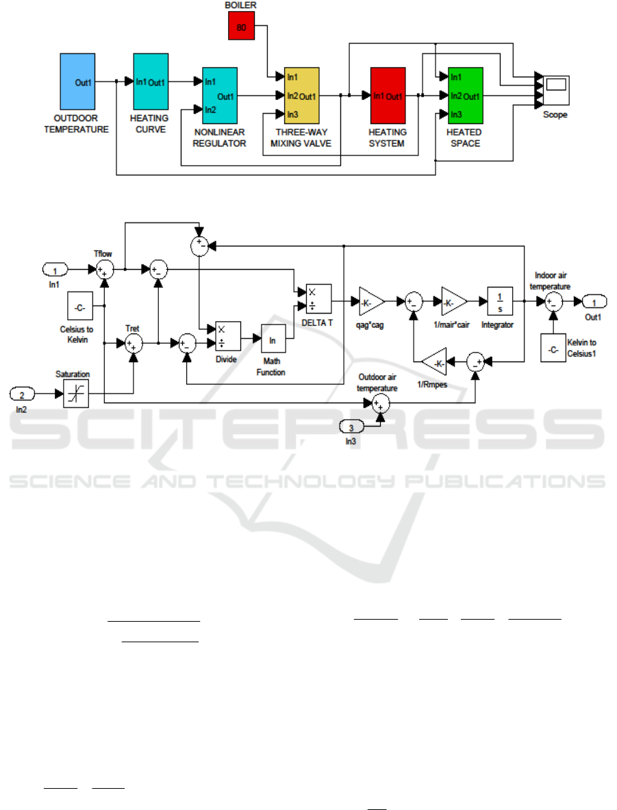
Figure 1: Block diagram of the automatic system modeled.
Figure 2: Simulink model for HEATED SPACE subsystem.
flow
T
- flow temperature
ret
T - return temperature
indoor
T - indoor temperature
The temperature difference between flow and
return of the heating installation, can be calculated
with the relation
indoorret
indoorflow
retflow
TT
TT
TT
T
−
−
−
=Δ
ln
(3)
which shows the connection between the indoor
temperature in the building and the water temperature
in the heating installation.
The heat losses through the building envelope that
correspond to the heated space, is calculated with the
relation
)(
1
outdoorindoor
mPE
out
TT
Rdt
dQ
−⋅= .
(4)
mPE
R
- average thermal resistance of the building
envelope
outdoor
T
- outdoor temperature
It is used the following simplifying hypothesis:
heat losses are only through the exterior wall, that has
the surface 20m x 10m = 200m
2
.
The equation which models the heated space in
the building is
airair
outinindoor
cmdt
dQ
dt
dQ
dt
dT
⋅
⋅
⎟
⎠
⎞
⎜
⎝
⎛
−=
1
.
(5)
air
m
- mass of air in the heated space
air
c
- specific heat of the air
The numerical values that need to be introduced
in the equation of the heated space model are
established further.
Mass of the air from the heated space
kgmmm
m
kg
Vm
airairair
2450101020225,1
3
=⋅⋅⋅=
=⋅=
ρ
.
MoMa-GreenSys 2016 - Special Session on Modelling Practical Paradigms of Green Manufacturing Systems
464
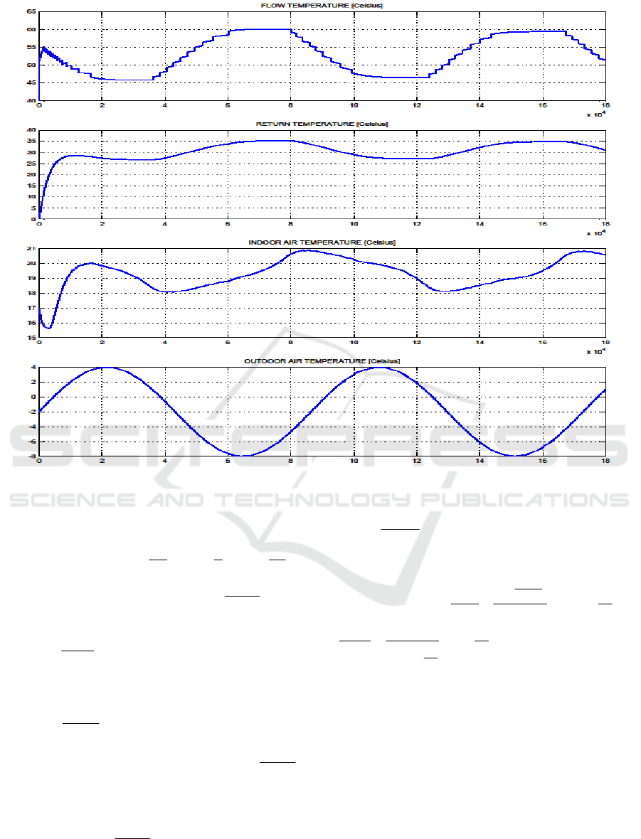
Figure 3: Results of simulation for the model of the automatic system.
The pump chosen for the circulation of the
thermal agent in heating installation has the
volumetric flow
s
kg
s
l
h
m
q
ag
694,0694,05,2
3
===
.
Specific heat of the air
Kkg
J
c
air
⋅
= 4,1005
.
Specific heat for thermal agent (water)
Kkg
J
c
ag
⋅
= 4190
.
Average thermal resistance of the building
envelope (exterior wall) has been chosen
W
Km
R
mPE
⋅
=
2
3,0
. A building envelope whose
average thermal resistance is 0,3 ... 0,5
⎥
⎦
⎤
⎢
⎣
⎡
⋅
W
Km
2
corresponds to uninsulated buildings. The reference
buildings are characterized by thermal resistance with
values of 0,6...0,7
⎥
⎦
⎤
⎢
⎣
⎡
⋅
W
Km
2
and the energy efficient
buildings are characterized by thermal resistance
values of
1...1,2
⎥
⎦
⎤
⎢
⎣
⎡
⋅
W
Km
2
.
The thermal resistance of the exterior wall with
surface S is
W
K
mm
W
Km
S
R
R
mPE
mPES
0015,0
1020
3,0
2
=
⋅
==
and
K
W
W
K
R
mPES
670
0015,0
11
≈=
.
The Simulink model for the subsystem called
heated space from the building is shown in Figure 2.
The heated space model allows recording the
indoor temperature, the main parameter which
evaluates the thermal comfort in the built space.
6 SIMULATION AND
EVALUATION OF THE MODEL
The model of the automatic system shown in Figure
1 represents the current situation in the building
Ensuring the Comfort in the Heated Space by Controlling the Temperature in the Heating Installation of a Non-residential Building
465

which belongs to the Faculty of Building Services
Engineering Bucharest.
The simulation of the model for the automatic
system is performed in a time interval that lasts
180,000 seconds, that is to say 50 hours. Time
interval for simulation was chosen large enough
compared with the values for the time constants of the
processes of heating in buildings and with the
transitory regime for an automatic heating system.
Through simulation were recorded the evolutions
for the temperatures from the heating system, indoor
temperature and outdoor temperature. The graphs are
shown in Figure 3 and represent the behavior of the
automatic system in winter days with normal
temperatures for Romania.
After passing the transitory time, caused by the
putting into service of automatic heating system, it is
found the correct correlation between flow
temperature from the heating installation
][KT
ft
and
outside temperature
][KT
ot
, according to equation
KKTKT
otft
87,732][5,1][ +⋅−=
.
(6)
This equation has been used for modeling the
subsystem HEATIG CURVE.
7 CONCLUSIONS
The model can be validated because, according to the
results of the simulation, it accurately represents the
actual physical characteristics of the automatic
system analyzed.
The variations obtained for the outside
temperature and the thermal agent temperatures in the
heating installation, as well as the correlations
between them, are in accordance with the
requirements for correct operation of the heating
installation in the non-residential building. In the
conformity assessment we must take into account that
the precision of choice for the slope of the HEATING
CURVE depends on the degree of knowledge of the
characteristics of the building.
A poor result was obtained for indoor air
temperature of the heated space. There are noted
maximum temperature variations
CCC
indoor
000
6,22,188,20 =−=Δ
θ
, which can be
felt as a discomfort by the building occupants.
The low thermal comfort arises because the
indoor temperature does not have an own control
loop. The indoor temperature in the heated space is
maintained approximately constant only by
controlling the thermal agent temperature in the
heating system depending on outside temperature. In
the temperature control of the thermal agent are
cumulated imprecisions that come from the non-
linear control, from the choice of the slope value in
HEATING CURVE and from the experimental
determination procedure of the mathematical model
for the heating installation.
The buildings and heating processes in non-
residential buildings are characterized by large and
very large thermal inertia, which is why the building
indoor temperature changes very slowly; these
variations of the indoor temperature represent a minor
thermal discomfort for the building occupants. Are
thus evident the main reasons for what the traditional
heating automation in buildings is based on the non-
linear control. An additional reason is the low price
for nonlinear automatic systems.
Local control of the indoor temperature in each
room of the building may be the ideal solution for
ensuring the thermal comfort of all building
occupants, but his high cost would allow rarely its
application.
REFERENCES
Clements-Croome, 2011. The interaction between the
physical environment and people. In: S.A. Abdul-
Wahab, ed. Sick building syndrome in public buildings
and workplaces. Berlin Heidelberg: Springer-Verlag,
239–261.
Oancea, C., Caluianu, S., 2012. Analysis of non-residential
buildings in Romania from the labour productivity and
intelligent buildings concept point of view. Intelligent
Buildings International, Volume 4, Issue 4, pages 216-
227, Publisher Taylor & Francis Ltd., ISSN 1750-8975.
Frontczak M, Schiavon S, Goins J, Arens E, Zhang H, and
Wargocki P., 2012. Quantitative relationships between
occupant satisfaction and aspects of indoor
environmental quality and building design. Indoor Air
Journal, Volume 22, Issue 2, 119-131. doi:
10.1111/j.1600-0668.2011.00745.x.
Mira, N. (coordinator), 2010. Technical Encyclopedia of
Installations, Volume E, ISBN 978-973-85936-5-7,
Publishing House Artecno Bucharest.
Ilina, M. (coordinator), 2010. Technical Encyclopedia of
Installations, Volume I, ISBN 978-973-85936-5-7,
Publishing House Artecno Bucharest, 2010.
DIEMATIC-m Delta, 2015. Control panel, Starting up and
operating Instructions, De Dietrich Thermique.
Available: http://www.dedietrich-thermique.fr.
Popescu, D., Ionescu, D., Iliescu, M., 2008. The fixed part
behavior of the heating automated systems in large
buildings, National Conference of Installations, Sinaia,
Romania, pp. 31-36, ISBN 978-973-755-406-2.
Popescu, D., Ciufudean, C., 2008. Automatic Control
System for Heating Systems in Buildings Based on
Measuring the Heat Exchange through Outer Surfaces.
MoMa-GreenSys 2016 - Special Session on Modelling Practical Paradigms of Green Manufacturing Systems
466

Proceedings of the 8th WSEAS International
Conference on Simulation, Modelling and
Optimization, pp. 117-121, ISSN 1790-2769.
Popescu, D., Ciufudean, C., Ghiauş, A., 2009. Specific
Aspects of Design of the Automated System for
Heating Control that Accounts for Heat Losses Through
the Building’s Envelope. Proceedings of the 13th
WSEAS International Conference on Systems, pp. 352
– 356, ISSN 1790-2768.
ISO 13789, 2007. Thermal performance of buildings-
Transmission and ventilation heat transfer coefficients-
Calculation method.
Ensuring the Comfort in the Heated Space by Controlling the Temperature in the Heating Installation of a Non-residential Building
467
