
Resilient Metro-scale Smart Structures: Challenges & Future Directions
Mike Burmester
1
and Jorge Munilla
2
1
Department of Computer Science, Florida State University, Tallahassee, FL 30302, U.S.A.
2
Campus de Excelencia Internacional Andalucia Tech, Universidad de Malaga, 29071 Malaga, Spain
Keywords:
Smart Structures, Resilience, Smart Grids, Supply Chain, Logistics, IoT.
Abstract:
Smart structures are highly inter-connected adaptive systems that are coordinated by cyber systems to optimize
specific system objectives. In this paper we consider the challenges for securing metro-scale smart structures.
We use a threat model that allows for untrusted behavior to capture realistic IoT scenarios, and discuss vul-
nerabilities, exploits and attack vectors. Resilience is defined in terms of stability, resistance to damage and
self-healing. To illustrate the challenges of capturing resilience we consider two very different applications:
supply chain logistics and smart grids. Both are mixed latency and throughput sensitive, each in their own
particular way. The first involves scanning RFID tagged objects in pallets. An untrusted RFID reader is given
a one-time authenticator to inspect a pallet and identify any missing objects; and, if there are no missing ob-
jects, compile a proof of integrity. The reader should not be able to trace objects via unauthorized inspections
(privacy). This application uses RS erasure codes that are more appropriate for memory constrained RFID
tags. The second application involves securing industrial substation automation systems. These are partic-
ularly vulnerable to cyber attacks, and HIL testbeds are used for real-time multilayer vulnerability analysis.
For metro-scale applications we propose virtualized testbeds that are portable and suitable for onsite incidence
response. For each application we show how metro-scale analytics are used to capture resiliency.
1 INTRODUCTION
The Internet of Things (IoT) links identifiable objects
to their virtual representation on the Internet making it
possible for an end user (process) to monitor and link
these to additional information regarding their status
for efficient control, management and logistics. This
extends the scope of the Internet making it possible
to control smart systems and structures (RAE, 2012),
in particular industrial control systems and critical in-
frastructures. In this paper we consider the challenges
of protecting such applications. Smart/critical infras-
tructures are a prime target for cyber attacks (The
White House, 2013). These may involve nation-state
(and ideological) actors, intelligence services, ter-
rorists, industrial spies, criminal groups, hacktivists,
hackers (e.g., botnet operators), spyware/malware au-
thors, etc., as well as insiders (ICS-CERT, 2015). At-
tacks may also be physical, or physical-enabled. Such
attacks enable the attacker to penetrate the layered de-
fenses of smart structures. To illustrate the challenges
we consider two applications: the first involves a sup-
ply chain while the second an electric grid. We show
how in both cases metro-scale analytics can be used
for resiliency.
The paper is organized as follows. In Section 2 we
model smart structures as tightly coupled ecologies
and define resilience in terms of survivability and self-
healing. We then consider two applications: a supply
chain in Section 3 and an electric grid in Section 4,
and show how to capture resilience. We conclude in
Section 5.
2 SMART STRUCTURES
Smart structures are highly inter-dependent systems
that integrate a tightly coupled mixed-latency ecol-
ogy (Figure 1) consisting of physical systems (sen-
sors, embedded devices, etc), social systems (oper-
ators, customers) financial systems and the environ-
ment (Miller and Page, 2009), that are coordinated by
Cyber system
Physical systems
Social systems
Financial systems
Environment
Figure 1: An infrastructure ecology.
Burmester, M. and Munilla, J.
Resilient Metro-scale Smart Structures: Challenges & Future Directions.
DOI: 10.5220/0005922501370147
In Proceedings of the International Conference on Internet of Things and Big Data (IoTBD 2016), pages 137-147
ISBN: 978-989-758-183-0
Copyright
c
2016 by SCITEPRESS – Science and Technology Publications, Lda. All rights reserved
137
A (real world adversary) controls all
communication channels
Physical Human Cyber
Human
A
෩
(ideal world adversary) controls
all communication channels
F (protected functionality)
Cyber
Physical
Physical
Human
Cyber
Figure 2: Real vs ideal world simulations.
cyber systems so as to optimize specific system ob-
jectives based on their properties and constraints, as
well as their current and estimated state.
Depending on the application, these structures are
called supervisory control and data acquisition sys-
tems (SCADA), industrial control systems (ICS), or
distributed control systems. Because of the interde-
pendencies, failure in any one of the components may
have a ripple (or cascade) effect on others and lead
to infrastructure disruption with potentially disastrous
impact on the services provided. Interdependencies
can be exploited by an adversary. It is well knownthat
dependent applications that run (concurrently) on the
same platform can lead to exploits that may compro-
mise the system, e.g., return-oriented programming
attacks (Roemer et al., 2012). However cross-domain
dependencies may also lead to exploits: Stuxnet used
USB flash drives to bridge the air gap protection of a
SCADA system (Langer, 2011).
Due to the potential catastrophic impact of infras-
tructure failure on the services provided, it is essen-
tial that mechanisms that support the integrity of op-
erations that monitor and control the system are em-
ployed: wrongly received/executed or dropped com-
mands may render the structure unstable (Burmester
et al., 2012; Guidry et al., 2012). Protection must en-
sure continuity of service, requiring real-time control,
and resist a formidable array of natural and man-made
hazards that include bad/faulty design, cyberspace at-
tacks and terrorist acts. In particular, it must resist
coordinated hazards. Protection must therefore ex-
tend to the components of systems and guarantee that
these do not get compromised. This shifts the focus of
smart structure protection towards resiliency, accen-
tuating self-healing and survivability behavior, that in
turn leads to risk management and threat mitigation.
2.1 Reliability & Resilience
Any attempt to provide holistic protection for highly
interdependent smart structures will fail because of
their complexity. The best we can aim for is risk man-
agement and threat mitigation.
Reliability typically refers to the proper function-
ing of the structure, as defined by its specifications
and policies, and captures fault-tolerance. There are
several definitions that describe different aspects of
resilience, depending on the application. For engi-
neering systems, resilience requires constancy, pre-
dictability and stability near an equilibrium steady
state; for social systems, a balance of self-organizing
systems; for environmental systems, resistance to
damage and quick response to natural perturbations/
disturbances: for financial systems, coping with
change and adapting to the consequences of failure.
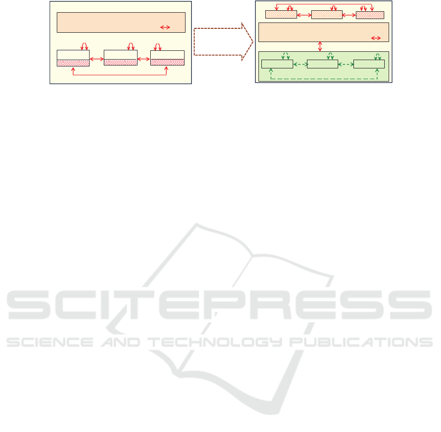
2.2 Threat Model
The UC formalization (Beaver, 1989; Canetti, 2001)
can be used to analyze the vulnerabilities of interde-
pendent applications and is ideally suited for study-
ing the threats of an infrastructure from a holistic
point of view. This models all parties, including ad-
versarial parties, by efficient processes (probabilis-
tic polynomial-time Turing machines) and uses a real
world simulation to model the actual behavior of the
system in the presence of a malicious (Byzantine) ad-
versary A (Figure 2, left), and an ideal world sim-
ulation to model the protected behavior of the sys-
tem (Figure 2, right), in which a trusted functional-
ity F enforces its protection policies—this captures
operational effectiveness. In the real world the ad-
versary A controls the communication channels be-
tween all parties (Figure 2, left: solid red arrows for
non-compromised parties and shaded green boxes for
compromised parties.). A may replay, modify/drop
or fabricate messages. In the ideal world the tasks
of non-compromised parties (dashed arrows) are ex-
ecuted by the functionality F that enforces the spec-
ifications and policies of the infrastructure, with the
adversary replaced by an ideal adversary
e
A that emu-
lates A . For UC-security, the two simulations should
be indistinguishable by any efficient process (the en-
vironment).
Although the UC-formalization is too restrictive
for resiliency, it can be used to describe and illus-
trate specific attacks. For example, an exploit can
be described as a cause-effect action X2Y involv-
ing X,Y ∈ {H,P,C}, H ∈ Human, P ∈ Physical and
IoTBD 2016 - International Conference on Internet of Things and Big Data
138
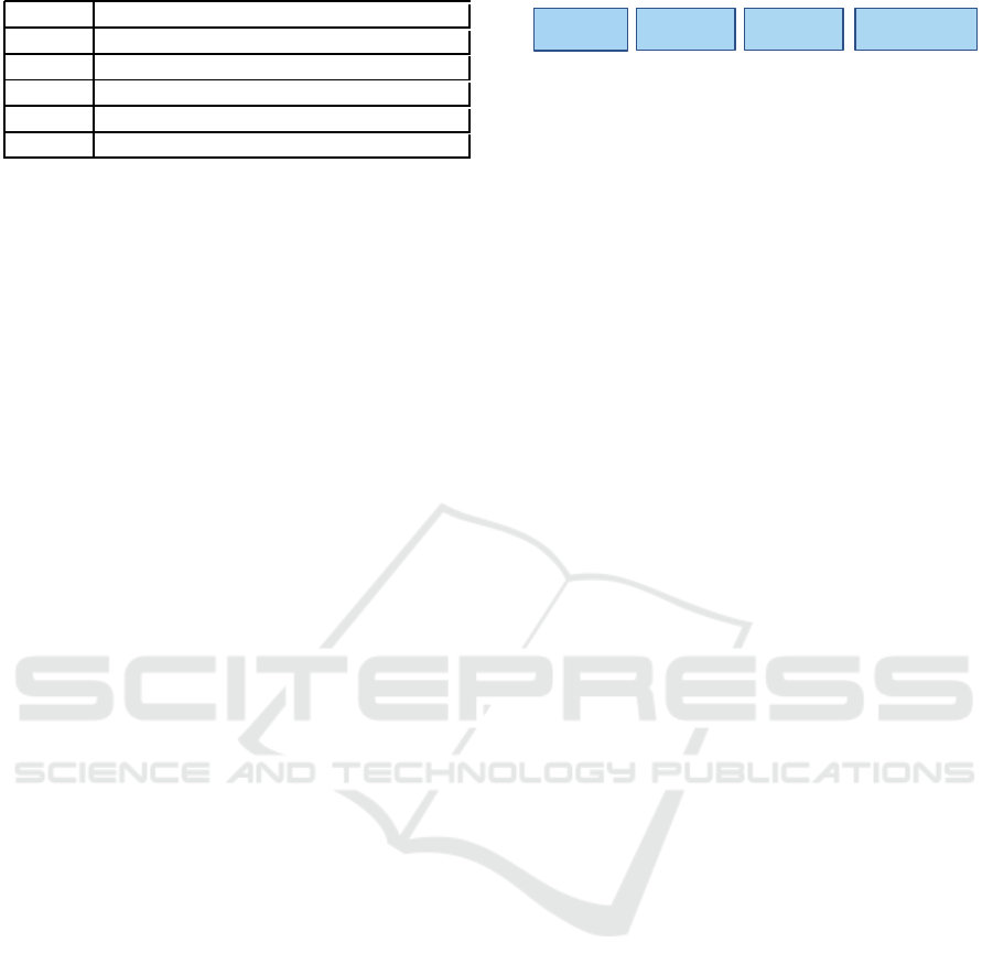
H2H
social engineering, impersonation, DOS
H2P,P2H impersonation (H), substitution (P)
H2C,C2H
impersonation (H), spoofing(C), phishing(C)
P2P substitution, DOS
P2C,C2P
substitution(P),air gap(P),side-channel,DOS
C2C side-channel, timing/power, ROP
Figure 3: Typical exploits of smart structures.
C ∈ Cyber (Yampolskiy et al., 2013), in which X
causes an effect on Y that results in the change of
Y’s state. Potential exploits are illustrated in Figure 2
by solid red arrows on the left; in the ideal simula-
tion they correspond to dashed green arrows, since
here we get the protection of the trusted functional-
ity F . Such exploits are clearly distinguishable by
the environment. Corrupted/compromised entities are
in shaded red boxes. The red solid arrows on the right
and left in Figure 2 are also exploits (e.g., insider)—
these are excluded from the UC formalization.
The adversary may also control some vertices:
vertex X may be infected by malware (X ∈ C), con-
tain compromised hardware (X ∈ P), or have decep-
tion capabilities (X ∈ H).
2.3 Attack Vectors
The graph G with edges the actions X2Y and vertices
in H ∪ P∪ C models the vulnerabilities of an infras-
tructure. The subgraph G
′
⊂ G consisting of the ex-
ploits X2Y is the threat graph. Any path of G that
shares an edge with G
′
is an attack vector. An attack
vector typically involves an action in which an adver-
sarial vertex delivers a malicious outcome to a target
vertex.
Figure 3 lists some common types of inter- and
cross-domain exploits with their corresponding de-
scription. H2H exploits involve social engineering;
P2Y (or Y2P), any Y, involve substitution: a phys-
ical object is substituted, damaged or compromised.
C2Y (or Y2C) exploits involve side-channel attacks
that undermine privacy, e.g., leak private key infor-
mation (Standaert et al., 2009), and return-oriented
programming that undermine integrity (Abadi et al.,
2009; Roemer et al., 2012). Air gaps (RFC 4949,
http://tools.ietf.org/html/rfc4949) are used to ensure
physical isolation of critical structures (such as mili-
tary computer systems, SCADA and ICSs) from un-
secured networks. Air gap exploits C2C use remov-
able media holes to bridge the gap—USB flash drives
were used by service contractors in the Stuxnet at-
tack (Langer, 2011).
Exploits that are known can be prevented by en-
forcing protection policies. However zero-day ex-
ploits that target previously unknown or undisclosed
compromise
flash drive
social
engineering
transfer
flash drive
deliver malicious
payload
൏ ࡴࡴࡴࡴ
Figure 4: Fragments of an air-gap attack vector.
vulnerabilities cannot be prevented until they get dis-
covered and analyzed. Attack vectors are a means by
which the adversary can deliver a payload or mali-
cious outcome to a smart structure, or for exfiltration.
Figure 4 illustrates an air-gap attack vector that deliv-
ers a malicious outcome: the adversary first uses an
H2C exploit to compromise a flash drive and then an
H2H social engineering exploit to fool a service con-
tractor that the flash drive is authentic. In the H2C
exploit the flash drive is transfered and in the C2C ex-
ploit a malicious outcome is delivered.
Threats such as these are a major security concern.
In particular advanced persistent threats (APT) that
employ C2P exploits using unexpected commands to
the programmable logic controllers (PLC) of smart
structures (the Stuxnet attack used an infected rootkit
to modify codes and send unexpected commands to
the PLC while returning a loop of normal operations
system values feedback to the user).
2.4 Security Assessment & Testing
This involves developing a security assessment pol-
icy and methodology as well as procedures and tools
for identifying system vulnerabilities. We refer the
reader to the NIST Technical Guide for Security Test-
ing and Assessment (SP800-115,2008). Here we note
that testing must include static and dynamic analysis,
white, gray, and black box testing, penetration testing,
simulation, and ensuring that the system components
or services are genuine. These are intended to un-
cover unintentional and intentional vulnerabilities in-
cluding, for example, malicious code, malicious pro-
cesses, defective software, and counterfeits.
We next consider two smart structure applications
that benefit from metro-scale analytics. These involve
a supply chain and a smart grid.
3 SUPPLY CHAIN LOGISTICS
RFID (Radio-Frequency Identification) is an emerg-
ing wireless technology that stimulated numerous in-
novative applications in several fields such as inven-
tory control, supply-chain management, and logistics,
as well as identify new research challenges and op-
portunities. A typical RFID deployment has three
main components: tags or transponders which are
Resilient Metro-scale Smart Structures: Challenges & Future Directions
139
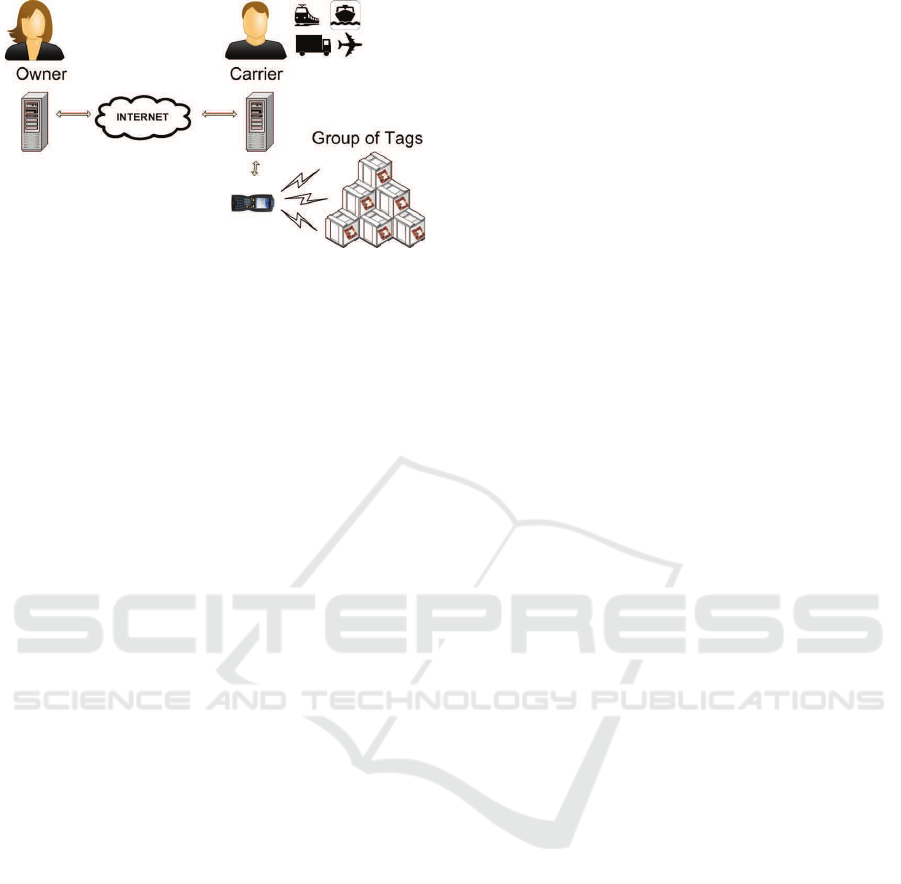
Figure 5: An untrusted Carrier can identify missing objects
in a pallet and compile a grouping-proof of integrity when
there are no missing objects.
electronic data storage devices attached to objects to
be identified, readers or interrogators that manage tag
populations and a back-end server (the verifier) that
exchanges tag information with the readers and pro-
cesses data according to specific task applications.
Most RFID tags are passive and do not have power of
their own but get the energy needed to operate from an
RFID reader. Passive tags are inactive until activated
by the electromagnetic field generated by a reader
tuned to their frequency. Although most RFID appli-
cations do not support privacy or integrity, the tech-
nology has now found use in many applications that
resist privacy and integrity threats. The recently rat-
ified EPC Gen2v2 standard incorporates privacy and
integrity mechanisms (EPC-Global, 2015).
3.1 Pallet Shipment Logistics: Integrity
& Privacy
When RFID technology is used for supply-chain
management, concerns regarding the monitoring and
transfer of ownership or control of tags have to be ad-
dressed. If the transfer is permanent, ownership trans-
fer protocols can be used (Kapoor and Piramuthu,
2012; Munilla et al., 2013). If the owner does not
want to cede control, even though this may only be
temporal, e.g., if a manufacturer uses a carrier who in
turn uses other carriers to transport products, then it
is desirable that the owner can periodically check the
integrity of a shipment via the carrier(s) (Figure 5).
This requirement is referred to as group scanning
and involves multiple tags generating a grouping-
proof of “simultaneous” presence in the range of an
RFID reader (Liu et al., 2013; Burmester and Mu-
nilla, 2013). Below we list some of the most common
security requirements for secure group scanning.
(a) The Owner (a trusted entity) can authorize an
RFID reader (an untrusted entity) to inspect the
pallet and identify any missing tagged objects.
(b) Theauthorizationisforoneonlyinspection,andthe
tags are untraceable via unauthorised inspections.
(c) The authorized reader can generate a grouping-
proof of integrity for a pallet if no tags are miss-
ing, while if some tags are missing can identify
these.
(d) Only the Owner can verify the grouping-proof.
In the rest of this section we review the literature
for RFID grouping scanning, discuss erasure codes,
and present an anonymous RFID grouping-proof of
integrity with missing tag identification appropriate
for metro-scale applications.
3.2 Background
Ari Juels introduced in 2004 the security context of
a new RFID application, called a yoking-proof (Juels,
2004), that generates evidence of simultaneous pres-
ence of two tags in the range of an RFID reader.
This protocol was later found to be insecure (Saito
and Sakurai, 2005; Juels, 2006) but, group scanning
triggered considerable interest in the research com-
munity with yoking-proofs extended to: grouping-
proofs for multiple tags (Piramuthu, 2006), anony-
mous grouping-proofs(Burmester et al., 2008; Huang
and Ku, 2008; Chien et al., 2009), and grouping-proof
for distributed RFID applications with trusted read-
ers (Liu et al., 2013).
While grouping-proofs provide evidence of in-
tegrity for complete groups, they do not address in-
complete groups, in particular they do not provide
any information about missing tags. In 2012 Sato et
al. proposed a grouping code that makes it possible
to find the identifiers of all tags of a group includ-
ing missing tags, without requiring a packaging list
or an external database (Sato et al., 2012). This is
based on Gallager low-density parity check (LDPC)
codes (RFC6816, 2013).
Forward error correction can increase the operat-
ing speed and reduce costs when it is difficult to ac-
cess a database with the corresponding information.
However the randomized nature of Gallager LDPC
codes makes it difficult to get specific decoding guar-
antees.
To address this issue, several variants were pro-
posed (Su et al., 2013; Su and Wang, 2015; Su and
Tonguz, 2013; Su, 2014; Ben Mabrouk and Couderc,
2015). However for these, the size of the blocks and
the partitioning of the redundancy is not optimal.
3.3 Erasure Codes
Let F
q
be a finite field of order q= p
m
, p a prime, m a
positive integer. A q-ary (n,k,s) erasure code is a lin-
IoTBD 2016 - International Conference on Internet of Things and Big Data
140

ear forward error correction code that encodes source
(input) data x = (x
1
,...,x
k
) ∈ F
k
q
to encoded data y =
(y
1
,...,y
n
) ∈ F
n
q
, in such a way that the source data
can be recovered if no more than s blocks y
i
∈ F
q
are
missing. We must have s≤ n−k (Singelton bound);
the optimal case s=(n−k) is reached with Maximum
Distance Separable (MDS) codes. The most com-
mon MDS codes are the Reed-Solomon (RS) codes
that are cyclic over F
q
, q > n, with minimum distance
d = n−k +1 = s+1.
In Section 3.4 we shall use an RS(n,k) code over
F
2
m
, 2≤m≤16 (based on the operational recommen-
dations of (RFC6865, 2013) for the values of m), to
encode the identifiers (id
1
,...,id
n
g
) of a collection of
n
g
RFID tags.
For this application the source data x = id
1
k ··· k
id
n
g
is an n
g
ℓ bit string, where ℓ is the binary length
of the identifiers id
i
. We rearrange x into k blocks
(x
1
,...,x
k
) ∈ F
k
2
m
(the last block is padded with ze-
ros if necessary). Then x is encoded to get an RS
codeword (y
1
,...,y
n
), with n/n
g
blocks stored in the
memory of each of the n
g
tags tag
i
, so as to recoverup
to s
t
= (n−k)/(n/n
g
) identifiers of missing tags. The
n/n
g
blocks of lenght m stored on tag
i
are denoted by
ID
i
and provide the identifying information id
i
as well
as the redundancy needed to recover missing data.
RS decoding can only be performed if the scanned
ID
i
are ordered correctly, with gaps for missing val-
ues. For this purpose control information is also
needed: each ID
i
is extended to include some ex-
tra bits that define the order i of tag
i
when its iden-
tifier was encoded. For example, if we use the
RS(150,120) code over GF(2
8
) for a collection of
n
g
= 10 tags with up to s
t
= 2 missing tags, then the
bit length of ID
i
is 124 bits, of which: 96 bits are
used for tag identifying data id
i
(as recommended by
EPC Gen2v2 (EPC-Global, 2015)), 24 bits for the re-
dundancy needed to recovermissing tag identification
data, and 4 bits for control (Burmester et al., 2016).
3.4 An Anonymous Grouping Proof
with Missing Tag Identification
The grouping proof is based on the design require-
ments in Section 3.1 and provides anonymity. In par-
ticular, the tags do not share any private information
with the interrogating reader R (an untrusted entity).
Protocol Description
For each group of tags G = {tag
1
,...,tag
n
g
} of the
owner V, V stores the tuple: (T
s
,K
g
,{(K
i
,ID
i
)}
n
g
i=1
),
where T
s
is a counter, K
k
a group key K
g
, and
(K
i
,ID
i
) the private key and identifier of tag
i
(Sec-
tion 3.3). Each tag
i
stores in non-volatile memory:
1a. R → ∗ : (T
s
,T
′
s
) (set timer)
b. tag
i
→ R : (r
i
,r
′
i
), i ∈ [1..n
g
] (set timer)
2a. R → ∗ : (R
s
,R
′
s
) (set timer)
b. tag
i
→ R : (r
i
,M
i
,M
′
i
⊕ID
i
,P
i
,P
′
i
), i∈ [1..n
g
] (timeout)
Grouping-proof: (T
s
,r
1
,.. .,r
n
g
,h(P
1
,.. .,P
n
g
))
Figure 6: Flows of the anonymous grouping-proof with
missing tag identification.
(ID
i
,K
g
,K
i
), and a counter T
s
i
that is initialized to
the same value T
s
for all tags of G. The reader ini-
tially does not share any information with the tags.
The protocol is initiated by the owner who sends to
the reader R a request (T
s
,T
′
s
,K
s
), where T
s
is a fresh
value of a counter, T
′
s
= h(K
s
,T
s
) is an authenticator
and K
s
= h(K
g
,T
s
) is the session key. The protocol
has two rounds—see Figure 6.
Round 1. R broadcasts to all tags in its range (T
s
,T
′
s
)
and sets a timer. Each tag
i
in range of R, computes
K
s
= h(K
g
,T
s
), checks that T
′
s
= h(K
s
,T
s
) and verifies
that T
s
> T
s
i
. If this fails it returns random values.
Otherwise it updates the counter to T
s
, draws a
pseudo-random number r
i
and computes its authen-
ticator r
′
i
= h(K
s
,r
i
). Then it sends (r
i
,r
′
i
) and sets
a timer. The received values r
i
are used to identify
(singulate) tags in this session. For every received
r
i
, the reader checks its integrity r
′
i
= h(K
s
,r
i
). If
this is correct, the value r
i
is stored as part of the
grouping proof. Using these values, R computes a
group session challenge R
s
= h(T
s
,r
1
,...,r
n
g
) and its
authenticator R
′
s
= h(K
s
,R
s
). This round incorporates
the randomness provided by the verifier’s challenge
T
s
and the randomness provided by the tags r
i
, which
prevent replay attacks. The challenge T
s
defines
the scanning period for the verifier, and the simul-
taneity by defining the validity period of the nonces r
i
.
Round 2. On timeout, R broadcasts (R
s
,R
′
s
) to all
tags in its range. Each tag
i
in range of R that has
not timed out, checks that R
′
s
= h(K
s
,R
s
) and if so,
computes:
M
i
= h(K
s
,r
i
,ID
i
), h(K
s
,M
i
) ⊕ ID
i
= M
′
i
⊕ ID
i
,
P
i
= h(K
i
,r
i
,R
s
), P
′
i
= h(K
s
,P
i
),
sends (r
i
,M
i
,M
′
i
⊕ ID
i
,P
i
,P
′
i
) to R and timeouts. R
computes M
′
i
= h(K
s
,M
i
), retrieves ID
i
and checks
that M
i
= h(K
s
,r
i
,ID
i
) and P
′
i
= h(K
s
,P
i
). If these
are correct, the reader verifies the integrity of the
group by using the codewords ID
i
. On timeout, if
the list of identifiers is complete, it compiles the
the grouping proof: (T
s
,r
1
,...,r
n
g
,h(P
1
,...,P
n
g
)) and
sends this to the verifier. If the list is not complete
Resilient Metro-scale Smart Structures: Challenges & Future Directions
141

then the reader R uses RS decoding to recover the
missing tag identifiers and informs the verifier. To
validate the proof, the verifier computes R
s
, and the
corresponding P
i
’s. Then, it checks that the received
h(P
1
,...,P
n
g
) is correct.
We shall assume that the keys K
g
,K
i
,K
s
, the chal-
lenges T
s
,R
s
and the random numbers r
i
, all have the
same (bit) length κ, which is the security parameter
of the protocol. The protocol has just two rounds and
only requires tags to be able to generate random num-
bers and compute a hash function.
Protocol Integrity & Privacy
The proof is informal. Integrity is established by the
use of authenticators, counters and timers. To forge a
grouping proof the adversary must compute the MAC
h(P
1
,...,P
n
).
An adversary that physically tracks a group of
tags G can determine which executions are linked
to this group; this cannot be prevented. Similarly
an adversarial reader that is authorized to inspect G
can link the inspected tags. Unlinkability concerns
periods during which physical tracking or authorized
inspection is interrupted. Since with each new
session every tag
i
updates its counter T
s
i
and draws
a fresh pseudo-random number r
i
after receiving the
reader’s authorized challenge, the responses of the
tags are pseudorandom and cannot be distinguished
with probability better than negligible.
Common RFID Attacks
Replay Attacks. The use of the counter T
s
by the
reader and the tags in the authenticators T
′
s
and r
′
i
pre-
vents replay attacks: if an adversarial reader re-uses
T
s
, the tags that received this earlier will have updated
their counter and will not respond. If a previous T
s
was never sent to the tags, then the tags will respond
(only this time) and a proof will be generated but this
will not be accepted by the verifier (T
s
is not valid).
Similarly a replayed response (r
i
,r
′
i
) for a previous
counter value T
s
will not be valid.
Impersonation Attacks on tags are prevented by
using private keys K
i
. Impersonation attacks on a
reader will not yield a valid proof: only readers that
have access to the one-time authorization (T
s
,K
s
) of
the verifier can interrogate G. The authorizations P
i
from different sessions cannot be used to compose a
proof since R
s
, which involves all the session nonces
from the different tags and the counter of the verifier,
is used to compute P
i
.
De-synchronization Attacks. If a protocol execu-
tion completes successfully then all tags will share the
same counter value. No tag will accept a previously
used T
s
. Even if tags do not share the same counter
value (e.g., because of an interrupted interrogation),
there are no synchronization concerns.
3.5 Metro-scale Logistics: RS vs LDPC
RS(n, k) codes are costly when n is large: encoding
and decoding have quadratic complexity. However
for pallet group scanning, the number of RFID tags is
not large (typically not more than 100 tags), and the
computational complexity is born by RFID readers
for which the computational and memory constraints
are not so strict, as opposed to the RFID tags that are
severely constrained. Indeed the tag memory-erasure
tradeoff for passive RFID tags is the limiting factor:
for collections of n
t
= 100 tags, with up to s
t
= 60
missing tags, we need: roughly 144 redundancy +
20 bits (Burmester et al., 2016), which is within the
bounds of EPC Gen2 (EPC-Global, 2015).
On the other hand Gallager LDPC codes can be
decoded in linear time. However this benefit can only
be realized by exceeding the memory constraints of
passive RFID tags.
4 SMART GRIDS
4.1 Background
With the advancements in computer and communica-
tion technologies, analog controls are been replaced
by networked digital devices that are far more effec-
tive to address the needs of smart structures because
of their programmability, flexibility and efficiency.
Historically, infrastructures relied mostly on propri-
etary technologies and were realized as stand-alone
systems with analog devices in physically protected
locations. The situation has changed considerably in
recent years. Commodity hardware, software, and
communication technologies are currently employed
by host infrastructures to enhance their connectivity
and improve the overall efficiency and robustness of
their operations. Unfortunately this has also signif-
icantly increased their vulnerability to cyber threats,
and hinder progress for more efficient management.
Former Defense Secretary Leon E. Panetta warned
recently that the United States was increasingly vul-
nerable to foreign computer hackers who have gained
access to the computer control systems of the nation’s
power grid, transportation system, financial networks
and government ..., and we are facing the possi-
bility of a “cyber-Pearl Harbor”.
1
The Stuxnet at-
1
http://blogs.wsj.com/cio/2012/10/11/u-s-defense-chief-
warns-of-digital-911/
IoTBD 2016 - International Conference on Internet of Things and Big Data
142

tack (Langer, 2011) and other more recent malware
attacks such as Havex
2
and the 2015 power plant sab-
otage in Ukraine
3
show that the threats are very real.
4.2 Real-time Availability for Grids
Electric Grids are mixed latency and throughput sen-
sitive infrastructures. To secure them it is essential
that the communication channels be protected in real-
time: correct messages delivered at the wrong time
could lead to erroneous system responses and failure.
Communication must therefore be subject to stringent
real-time requirementsthat render commonly adopted
security paradigms for cyber-only systems inapplica-
ble. For example, confidentiality, integrity and avail-
ability are the primary goals of cyber security with
confidentiality (privacy) being most important. How-
ever for grids that are latency sensitive, availability
and integrity become the primary goals, with confi-
dentiality often a secondary goal.
There have been several efforts to secure electric
grids primarily based on extending mechanisms al-
ready used to protect their separate cyber and phys-
ical components. However, there is no formal secu-
rity framework that deals with software threats, hard-
ware threats, network threats, and physical threats
in a comprehensive way. Without a unified secu-
rity framework, approaches to securing grids are ad-
hoc and cannot provide proven requirements for real-
world systems, therefore hindering their adoptability.
4.3 IEC 61850 & IEC 62351
IEC 61850 is a standard of the International Elec-
trotechnical Commission for power utility automa-
tion (IEC61850, 2007) that integrates protection,
control, measurement and monitoring. The stan-
dard offers advanced object oriented semantics for
information exchange in power utility applications,
SCADA, system protection, substation automation,
etc, and supports advanced communication with
an integrated, fully managed Ethernet switch and
Internet TCP/IP communication protocols. The
IEC62351 (IEC62351, 2015) standard is a security
extension for data communication.
4.4 An IEC 61850 Resilience Framework
for Compliant Systems
The Framework is based on the NIST Technical
Guide for Security Assessment & Testing (SP800-
2
https://ics-cert.us-cert.gov/alerts/ICS-ALERT-14-176
3
http://www.theguardian.com/world/2015/nov/22/crimea-
state-of-emergency-power-lines-attacked
output power
backup power
sustained functionality level
time
Figure 7: Maintaining functionality at a sustained level.
115, 2008) discussed in Section 2.4 and extends IEC
62351 to capture system resilience. This involves the:
1. Analysis of real-time multi-layer vulnerabilities &
threats to electric grids resulting from untrusted or
unexpected behavior.
2. Analysis of cascading electric grid faults and find-
ing time-to-restore solutions that maintain sus-
tained functionality levels.
3. Identification of vulnerabilities & threats of IEC
61850 compliant grids and the design policies/
mechanisms that support resilience.
The framework should be regarded only as a first step.
Infrastructures are complex adaptive systems (Miller
and Page, 2009), and protecting them has to be an on-
going process that evolves, and accounts for changes
in policies/specifications and threat scenarios.
4
In
particular, resilience must address:
– Adaptation threats: system policies and specifi-
cations must adapt to address emergent behavior.
This may be driven by the adversary.
– Insider behavior and zerodays: Offensive security
architectures and real-time stochastic analyzers.
4.5 Maintaining Functionality at
Sustained Levels
Resilient systems must be self-healing: when a prob-
lem is detected in real-time, it must be isolated to
maintain functionality at sustained power levels dur-
ing emergencies, until the problem is addressed. Cur-
rently grids may experience cascading failures in
emergency situations where outages are poorly con-
tained.
5
Although the technologies for containing
cascading failures continue to improve,their ability to
contain failure in real-time implementations has not
been tested (e.g., hardware-in-the-loop testing). In
particular in adversarial scenarios. A recent report
4
The Kerberos authentication protocol proposed in the late
1980’s, was modified several times.
5
NASEO: http://www.naseo.org/data/sites/1/documents/pub
lications/NASEO
Smart Grid and Cyber Security for En
ergy
Assurance rev November 2011.pdf
Resilient Metro-scale Smart Structures: Challenges & Future Directions
143
Control Center
Internet
Remote Operator
Other Substations
= Vulnerability/exploit
5
Substation Bus, Ethernet
Process Bus, Ethernet
Relay
Meter
MU MU
HMI
IED
A Substation
Automation System
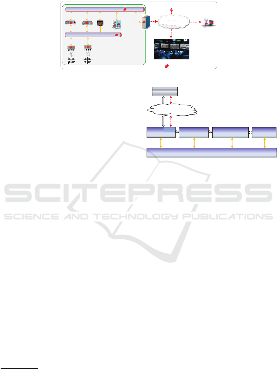
Figure 8: Vulnerabilities of an IEC 61850 enabled substation automation system.
in USA Today
6
observes that because electrical grids
operate as an interdependent network failure in any
one element requires energy to be drawn from other
areas implying that if multiple parts fail at once this
may lead to a cascading failure. The report mentions
several game changer incidents such as the coordi-
nated attack on the Metcalf substation of the Pacific
Gas & Electric Co on 4/16/2013, as well as 362 other
physical and cyber attacks on public utilities between
2011 and 2015.
Addressing cascading failures will require backup
energy storage for time-to-restore capability (Fig-
ure 7), and significantly more automated controls.
Several energy storage technologies can be used for
backup power, such as pumped hydro, compressed
air energy storage, flywheels, batteries and superca-
pacitors, hydrogen fuel cells, etc. Energy storage will
have to be combined with a fast-simulation and mod-
eling tool that gathers information, makes decisions
and takes control actions.
4.6 Vulnerabilities of IEC 61850
Compliant Systems
Figure 8 shows the vulnerabilities of an IEC 61850
compliant substation automation system. In the
“switchyard” (bottom left), Brick Merging Units
(MU) provide diagnostics to monitor and protect
power generators. In the control house (top left), In-
telligent Electronic Devices (IED) and Relays moni-
tor and control the power supply. The MU and IED
are networked. One (or more) of the IED has Eth-
ernet connectivity to a SCADA control system and a
Human Machine Interface (HMI). Internet connectiv-
ity is available for software updates and other checks.
To analyze the vulnerabilities of the individual
components of such systems one has to assess and
test specific industrial realizations. The General Elec-
tric (GE) Multilin HardFiber System is an IEC 61850
6
Steve Reilly, SpecialReport, 03.25.2015: http://www.13ne
wsnow.com/story/news/2015/03/25/bracing-for-a-big-po
wer-grid-attack-one-is-too-many/70417150/
SCADA
Hardfiber Brick MU
G60
Generator Protection
TCP/IP
D60
Trans Line Protection
C60, F60
Breaker, Feeder Protection
N60
Network Stability
Figure 9: GE Multilin HardFiber System Architecture.
compliant substation automation system that maps
switchyard measurements to protection relays located
in the control house using secure communications
(a single fiber optic cable is used, eliminating most
of the field wiring). This system consists of sev-
eral components, including (Figure 9): a Multilin
Brick Merging Unit (MU), Cross Connect Panels,
the Protection Relays: C60 (Breaker Protection), F60
(Feeder Protection), the IEDs: G60 (Generator Pro-
tection), D60 (Transmission Line Protection), and
N60 (Network Stability and Synchrophasor Measure-
ment System). The transmission channels are either
IEC61850 control fiber, switchyard fiber or TCP/IP
channels (dotted red arrows). IEC61850 channels
include: MMS (Manufacturing Message Specifica-
tion), GOOSE (Generic Object Oriented Substation
Events), and SMV (Sampled Measured Values) chan-
nels. Multilin uses: MultiLink ML2400 and Multi-
Link ML1600 switches for Ethernet and UR Switch
Modules.
4.7 Threat Analysis
The IED G60 in Figure 9 has advanced automa-
tion capabilities for customized protection and con-
trol solutions, in particular for updating firmware via
TCP/IP channels. This exposes the Multilin system
to several threats in which an attacker can gain ac-
cess to G60 via a TCP/IP channel (an H2C exploit,
Section 2.2) to deliver a malicious outcome, e.g., to
IoTBD 2016 - International Conference on Internet of Things and Big Data
144

upgrade the system with compromised firmware, or
for firmware manipulation/tampering.
G60 has an LED display panel that will indicate
anomalies. However an attacker can manipulate the
display to show an incorrect state of the network envi-
ronment. G60 has also the ability to program user but-
tons. The attacker can reprogram one of the buttons
(an H2P exploit) and force a false LED alarm display.
A controller may then push the button (H2P ⇒ P2C
attack) which in turn may disable a switch or shut-
down a generator (a C2P exploit). These exploits
involve social engineering, or use vulnerabilities not
previously identified.
The IED D60 and N60 use the IEEE 802.1q pro-
tocol to carry VLAN (Virtual Local Area Network)
GOOSE traffic over the Ethernet. This protocol sup-
ports priority queueing. If an attacker A has access
to the VLAN used by the IED to communicate (an
H2C exploit), then A can send high priority pack-
ets to the IEDs and prevent true high priority control
packets from being processed. This could cause criti-
cal GOOSE messages to be delayed from processing,
that may turn-off a breaker, due to invariances in the
electric monitoring (a C2P exploit).
Another vulnerability of the Multilin IEDs in-
volves MMS IEC 61850 channels. If an attacker A
can extract an SSH public key (e.g., using an H2C ex-
ploit) then A can use an MMS to update an IED via
SSH, or install malware. If the IED do not support
authorization and integrity then the IED can easily be
compromised with LAN sniffing or by using device
vulnerabilities (an H2C exploit). For example, A can
send a control messages to an IED to cause an elec-
trical switch to open causing unknown issues to the
electrical grid.
It is essential to stress test all IEC 61850 devices
and determine their threshold behavior—the potential
exploits. Also, to test the system for vulnerabilities
that an attacker can exploit to gain access to the IED,
Relays and MU, via the SCADA/HMI system.
4.8 Hardware-In-the-Loop (HIL)
Testbeds
A number of testbeds for Industrial Control Systems
(ICS) have been developed to discover new vul-
nerabilities and to analyze attack patterns and their
impacts. Many of these support HIL testing. The
most notable testbed is the National SCADA Test
Bed (NSTB) that draws on the integrated expertise
and capabilities of the Argonne, Idaho, Lawrence
Berkeley, Los Alamos, Oak Ridge, Pacific North-
west, and Sandia National Laboratories to address the
cybersecurity challenges of energy delivery systems
7
.
The NSTB testbed combines real hardware (sen-
sors, actuators, PLCs, IEDs, etc.), software (super-
visory and control systems, etc.) and emulate HMI.
There are also joint academia and industry testbeds
such as the Trustworthy Cyber Infrastructure for
Power Grids (TCIPG) of the University of Illinois,
ExoGENI-WAMS-DETER of NC State University
and ISI’s DETER-lab. These are Real-Time-Digital-
Simulator (RTDS) testbeds for HIL testing.
Analyzing memory corruption vulnerabilities of
ICS embedded systems on hardware based testbeds
often runs the risk of damaging or destroying the
testbed hardware (Redwood et al., 2016) Since these
testbeds are highly complex and costly, alterna-
tive solutions should be sought for memory corrup-
tion exploits. Software based ICS testbeds, unlike
their hardware counterpart, are portable, and dis-
tributable. However virtualizing embedded systems
is non-trivial, especially at the firmware level, with
current solutions failing to distinguish certain attack
patterns. Recent advances in physics simulation and
microprocessor virtualization emulators have made it
possible to consider methodologies that integrate sim-
ulated physics and embedded virtualization. This is a
first step towards realistic software based ICS testbeds
that can be used for onsite incidence response (Red-
wood et al., 2016).
4.9 Metro-scale Grids: Soft vs Hard
ICS Testbeds
As observed above, hardware based ICS testbeds are
restricted to particular classes of malware analysis
and cannot be used for onsite incidence response.
Current software based testbeds can only emulate
small networks. However recent advances in micro-
processor virtualization emulators and physics sim-
ulation have made possible the design of soft ICS
testbeds that can be used for onsite analysis without
risk of damaging the testbed (Redwood et al., 2016).
5 CONCLUSIONS
We have considered two very different smart struc-
ture applications to illustrate the challenges of se-
curing such structures. The first involves the supply
chain: an untrusted RFID reader has to identify miss-
ing tagged objects in a pallet, and compile a proof of
integrity if no tagged objects are missing. The reader
7
http://energy.gov/oe/technology-development/energy-deli
very-systems-cybersecurity/national-scada-test-bed
Resilient Metro-scale Smart Structures: Challenges & Future Directions
145

does not share any secret information with the tags,
and is only given a one-time authenticator. The reader
should not be able trace tagged objects of pallets
that where not inspected (privacy). For applications
with pallets having no more than 100 tagged items
this is possible by using RS erasure codes. Larger
pallets require a different approach, since for these
the memory-erasure tradeoff is excessive for passive
RFID tags.
The second application involves IEC 61850 com-
pliant industrial systems: we considered the GE Mul-
tilin HardFiber system. In this case resiliency can
only be established if the components of the system
function as intended. In particular, they should not
be compromised. To establish this, ICS testbeds are
used. Hardware testbeds are costly and risk being
damaged if the memory of tested components is cor-
rupted. Also, they cannot be used for onsite malware
analysis. On the other hand software testbeds can
only emulate small networks. For high-end metro-
scale applications a software based approach is pro-
posed (a proof of concept) that integrates simulated
physics and embedded virtualization.
ACKNOWLEDGEMENTS
This material is based in part upon work supported
by: (a) the National Science Foundation under Grant
Numbers CNS 1347113, DUE 1241525, 1027217and
DGE 1538850, (b) the NSA/DHS under grant BAA-
003-15 and (c) Spanish MINECO and FEDER under
project TEC2014-54110-R.
REFERENCES
Abadi, M., Budiu, M., Erlingsson,
´
U., and Ligatti, J.
(2009). Control-flow integrity principles, implemen-
tations, and applications. ACM Transactions on Infor-
mation and System Security (TISSEC), 13(1):4.
Redwood, W.O., Reynolds, J., and Burmester, M. (2016).
Soft ICS Testbeds: A Simulated Physics and Em-
bedded Virtualization Integration (SPAEVI) Method-
ology. In Rice, M. and Shenoi, S. editors, Critical
Infrastructure protection X, Springer.
Burmester, M. and Munilla, J. (2016). An Anonymous
RFID Grouping-Proof with Missing Tag Identifica-
tion. 10th IEEE International Conference on Radio-
Frequency Identification, 3-5 May, Orlando. U.S.A.
Beaver, D. (1989). Multiparty protocols tolerating half
faulty processors. In Brassard, G., editor, Advances
in Cryptology - CRYPTO ’89, 9th Annual Interna-
tional Cryptology Conference, Santa Barbara, Cali-
fornia, USA, August 20-24, 1989, Proceedings, vol-
ume 435 of Lecture Notes in Computer Science, pages
560–572. Springer.
Ben Mabrouk, N. and Couderc, P. (2015). EraRFID: Re-
liable RFID systems using erasure coding. In RFID,
2015 IEEE International Conference, pages 121–128.
Burmester, M., de Medeiros, B., and Motta, R. (2008).
Provably Secure Grouping-Proofs for RFID Tags. In
Grimaud, G. and Standaert, F.-X., editors, CARDIS,
volume 5189 of Lecture Notes in Computer Science,
pages 176–190. Springer.
Burmester, M., Magkos, E., and Chrissikopoulos, V. (2012).
Modeling Security in Cyber-Physical Systems. Inter-
national Journal of Critical Infrastructure Protection
(IJCIP), 5(3-4):118–126.
Burmester, M. and Munilla, J. (2013). Security and
Trends in Wireless Identification and Sensing Plat-
form Tags: Advancements in RFID, chapter RFID
Grouping-Proofs. IGI Global.
Canetti, R. (2001). Universally composable security: a
new paradigm for cryptographic protocols. Proceed-
ings, 42nd IEEE Symposium on In Foundations of
Computer Science, Foundations of Computer Science,
pages 136–145.
Chien, H.-Y., Yang, C.-C., Wu, T.-C., and Lee, C.-F. (2009).
Two rfid-based solutions to enhance inpatient medica-
tion safety. Journal of Medical Systems.
EPC-Global (2015). Radio-Frequency Identity Protocols,
Generation-2.V2. UHF RFID. Technical report.
Guidry, D., Burmester, M., Yuan, X., Liu, X., Jenkins, J.,
and Easton, S. (2012). Techniques for securing sub-
station automation systems. In 7th Int. Workshop on
Crit. Inform. Infrastr. Secur.(CRITIS).
Huang, H.-H. and Ku, C.-Y. (2008). A RFIDgrouping proof
protocol for medication safety of inpatient. Journal of
Medical Systems.
ICS-CERT (2015). Cyber Threat Source Descriptions. In-
dustrial Control Systems, Cyber Emergency Response
Team.
IEC61850 (2007). Parts 1-10, Power Utility Automation.
http://www.iec.ch/smartgrid/standards/.
IEC62351 (2015). Parts 1-8, Information Security for
Power System Control Operations. http://www.iec.ch/
smartgrid/standards/.
Juels, A. (2004). “Yoking-proofs” for RFID tags. In PER-
COMW ’04: Proceedings of the Second IEEE Annual
Conference on Pervasive Computing and Communi-
cations Workshops, pages 138–142, Washington, DC,
USA. IEEE Computer Society.
Juels, A. (2006). Generalized “yoking-proofs” for a group
of RFID tags. In MOBIQUITOUS 2006.
Kapoor, G. and Piramuthu, S. (2012). Single RFID Tag
Ownership Transfer Protocols. IEEE Transactions on
Systems, Man, and Cybernetics, Part C, 42(2):164–
173.
Langer, R. (2011). Cracking Stuxnet, a 21st-century cyber
weapon. Entertainment and Design.
Liu, H., Ning, H., Zhang, Y., He, D., Xiong, Q., and Yang,
L. T. (2013). Grouping-proofs-based authentication
protocol for distributed RFID systems. IEEE Trans.
Parallel Distrib. Syst., 24(7):1321–1330.
IoTBD 2016 - International Conference on Internet of Things and Big Data
146

Miller, J. H. and Page, S. E. (2009). Complex Adaptive
Systems: An Introduction to Computational Models of
Social Life. Princeton University Press.
Munilla, J., Guo, F., and Susilo, W. (2013). Cryptanalysis of
an EPCC1G2 Standard Compliant Ownership Trans-
fer Protocol. Wireless Pers Commun, (72):245–258.
Piramuthu, S. (2006). On existence proofs for multi-
ple RFID tags. IEEE Int. Conf. Pervasive Services,
Workshop on Security, Privacy and Trust in Pervasive
and Ubiquitous Computing – SecPerU 2006, Lyon,
France. IEEE, IEEE Computer Society Press.
RAE (2012). Smart infrastructure: the future, The Royal
Academy of Engineering. ISBN 1-903496-79-9.
RFC6816 (2013). Simple Low-Density Parity Check
(LDPC) Staircase Forward Error Correction (FEC)
Scheme for FECFRAME.
RFC6865 (2013). Simple Reed-Solomon Forward Error
Correction (FEC) Scheme for FECFRAME.
Roemer, R., Buchanan, E., Shacham, H., and Savage, S.
(2012). Return-oriented programming: Systems, lan-
guages, and applications. ACM Transactions on Infor-
mation and System Security (TISSEC), 15(1):2.
Saito, J. and Sakurai, K. (2005). Grouping proof for
RFID tags. In 19th International Conference on
Advanced Information Networking and Applications,
AINA 2005., volume 2, pages 621–624.
Sato, Y., Igarashi, Y., Mitsugi, J., Nakamura, O., and Murai,
J. (2012). Identification of missing objects with group
coding of RF tags. In RFID, 2012 IEEE International
Conference on, pages 95–101.
SP800-115 (2008). NIST, Technical Guide to Information
Security Testing and Assessment.
Standaert, F.-X., Malkin, T. G., and Yung, M. (2009). A
unified framework for the analysis of side-channel
key recovery attacks. In Advances in Cryptology-
EUROCRYPT 2009, pages 443–461. Springer.
Su, Y. and Wang, C. (2015). Design and analysis of un-
equal missing protection for the grouping of rfid tags.
Communications, IEEE Transactions on, PP(99):1–1.
Su, Y.-S. (2014). Extended Grouping of RFID Tags Based
on Resolvable Transversal Designs. Signal Processing
Letters, IEEE, 21(4):488–492.
Su, Y.-S., Lin, J.-R., and Tonguz, O. K. (2013). Grouping
of RFID Tags via Strongly Selective Families. IEEE
Communications Letters, 17(6):1120 – 1123.
Su, Y.-S. and Tonguz, O. K. (2013). Using the Chi-
nese Remainder Theorem for the Grouping of RFID
Tags. Communications, IEEE Transactions on,
61(11): 4741–4753.
The White House (2013). Executive Order, Improving Crit-
ical Infrastructure Cybersecurity. Office of the Press
Secretary.
Yampolskiy, M., Horvath, P., Koutsoukos, X. D., Xue, Y.,
and Sztipanovits, J. (2013). Taxonomy for description
of cross-domain attacks on cps. In Proceedings, 2nd
ACM International Conference on High Confidence
Networked Systems, pages 135–142. ACM.
Resilient Metro-scale Smart Structures: Challenges & Future Directions
147
