
Comparison of Topological Functioning Model for Software
Engineering with BPMN Approach in the Context of Model Driven
Architecture
Janis Osis and Arturs Solomencevs
Department of Applied Computer Science, Riga Technical University, Riga, Latvia
Keywords: Topological Functioning Model, Model Driven Architecture, Formal CIM, CIM to PIM Transformation.
Abstract: OMG’s Model Driven Architecture (MDA) proposes a computation independent view on the information
system. It is used to specify the requirements and to describe how the system works within its environment.
The key part of MDA is model transformation. Computation independent model (CIM) must be transformed
to a platform independent model (PIM). The problem is that software development approaches that hold by
MDA principles have informal models on CIM level. Without mathematical formalism, it is not possible to
properly transform CIM to PIM. Topological Functioning Model for Software Engineering (TFM4SE)
approach addresses this issue, and applies Topological Functioning Model (TFM) as a formal CIM. In this
paper, TFM4SE is compared to approach that uses Business Process Model and Notation for CIM modeling.
The comparison focuses on CIM modeling and on transformation to class diagram on PIM level. The results
show what advantages and drawbacks does the formalism of TFM bring into the software development.
1 INTRODUCTION
OMG’s Model Driven Architecture (MDA) is an
approach to system development, which increases the
power of models in this work. The purpose of MDA
is to separate the views and concerns. MDA has three
viewpoints on the system and their corresponding
models: a computation independent model (CIM)
describes system requirements and the way the
system works within its environment, while details of
the application structure and realization are hidden;
platform independent model (PIM) focuses on the
operation of a system while hiding the details
necessary for a particular platform; and platform
specific model (PSM) (Miller and Mukerji, 2003).
Model transformation forms a key part of MDA. To
get the software source code we need to go by the path
CIM → PIM → PSM → source code.
We believe that it is essential to start software
development with modeling the business system, or
in other words with modeling the environment of the
planned information system (Osis, 2004), (Osis and
Asnina, 2011 a). Understanding of how the
information system will interact with the business
system leads to an appropriate design. So CIM needs
to be created in the beginning of the development
process – this assertion is the basis of this article.
The problem domain is the part of the world in
which the software is required to bring about some
effect desired by the customer (Osis, 2004). The
solution domain is a system (e.g., business system)
which is supported by the planned information
system. Both problem domain and solution domain
can be specified by CIM (Asnina and Osis, 2010).
The solution domain CIM must conform to the
problem domain CIM. It is possible to transform the
solution domain CIM to PIM level design models
(Osis, Asnina and Grave, 2007).
There is a shortcoming in MDA guide (Miller and
Mukerji, 2003). OMG says nothing essential about
the computation independent view and accordingly
about the CIM. The weakness of MDA is that there is
nothing well formalized and/or transformable at the
beginning of the software development life cycle
(Osis and Asnina, 2011 a).
Our group works on dealing with the mentioned
issue, and develops an approach called “Topological
Functioning Model for Software Engineering”
(TFM4SE). This approach uses Topological
Functioning Model (TFM) as a formal CIM.
TFM is a mathematically formal model which
describes the functioning of a system. TFM has a
solid mathematical base. It is represented in a form of
a topological space (X, Θ), where X is a finite set of
Osis, J. and Solomencevs, A.
Comparison of Topological Functioning Model for Software Engineering with BPMN Approach in the Context of Model Driven Architecture.
In Proceedings of the 11th International Conference on Evaluation of Novel Software Approaches to Software Engineering (ENASE 2016), pages 337-348
ISBN: 978-989-758-189-2
Copyright
c
2016 by SCITEPRESS – Science and Technology Publications, Lda. All rights reserved
337

functional features of the system under consideration,
and Θ is topology that satisfies axioms of topological
structures and is represented in a form of a directed
graph. The TFM’s functional features describe the
system’s physical or biological characteristics that are
relevant for the normal functioning of the system. The
TFM’s topology consists of cause-effect relations
between functional features. Cause-effect relation
exists between two functional features, if appearance
of one functional feature is caused by appearance of
the other without participation of any intermediate
functional feature. Cause-effect relations form causal
chains. Causal chains must form at least one
functioning cycle within TFM. All the cycles and
subcycles should be carefully analyzed in order to
completely identify existing functionality of the
system. TFM views system as a whole and not as a
collection of parts – the model is holistic (Osis, 1969).
In our opinion, the improvement of the results of
object-oriented system analysis and modelling lays in
using formal methods. Formal approaches allow
defining formal or semi-formal model
transformations (the key part of MDA) and formal
tracing of modeling artifacts. Formalism helps
finding inconsistencies in the domain model. In TFM,
for example, analysis of cycles helps with this task.
Furthermore, the power of traditional engineering is
that engineers do trust in theory, mathematics and
formal methods (Osis and Asnina, 2011 a), and this
power can be used in software development.
TFM4SE is a formal method, which has a
mathematical model – TFM – in its core.
The goal of the current research is to compare
TFM4SE with other model-driven approaches that
suggest creating CIM level models which can be
transformed to PIM. For this paper, we narrow the
scope and review approaches that use BPMN models
(OMG BPMN, 2013) on CIM level. BPMN is widely
used in software development for business modeling.
This notation is easy to work with and is
understandable for business people and software
developers (training is required to freely use it).
BPMN does not have mathematical background, so it
is a mathematically informal notation. Therefore we
are interested in comparing CIM-TFM to CIM-
BPMN, and find out what benefits and what
drawbacks brings the formalism of TFM comparing
to informal BPMN business model in the field of
software development.
The paper is structured as follows. In Section 2 we
briefly review approaches that provide CIM → PIM
transformation, that were discovered during the
research; and we represent the major opportunities of
TFM4SE. In Section 3 the comparison of TFM4SE
with one of the CIM-BPMN approaches on basis of
an example is made. In Section 4 conclusions are
presented.
2 RELATED WORK
There are different software developments
approaches that use BPMN for CIM modeling and
provide CIM → PIM transformation. Approach
described in (Rhazali, Hadi and Mouloudi, 2014)
applies BPMN collaboration and business process
diagrams on CIM level, and defines rules for
transformation to UML Class diagram and Use case
diagram on PIM level. Service-oriented approach
(Fazziki et al., 2012) proposes to transform BPMN
models into SoaML model (OMG SoaML, 2012) and
into UML Component model. Method of (Hahn,
Panfilenko and Fischer, 2010) is also service-
oriented, and also uses SoaML for PIM modeling.
Another service-oriented approach – (Castro, Marcos
and Vara, 2011) – applies use case model and activity
diagram on PIM level. Research of (Rodriguez et al.,
2010) focuses on security requirements, and models
security along with business processes. (Bousetta, El
Beggar and Gadi, 2013 a) approach provides ways of
getting class diagram and sequence diagrams from
BPMN business process models.
Not only BPMN is applied for CIM modeling. An
approach represented in (Zhang et al., 2005) adopts
features and components as the key elements of CIM
and PIM, respectively. Paper (Gutierrez et al., 2008)
proposes to automatically generate an activity
diagram from a use case description. Data warehouse
development method (Mazon, Pardillo and Trujillo,
2007) uses a UML profile for the i* modeling
framework (Yu, 1995) for CIM modelling, and
provides transition to conceptual model on PIM level.
Research of (Kherraf, Lefebvre and Suryn, 2008)
proposes to use UML activity diagram to model the
business processes and to specify the system
requirements, and to transform CIM into PIM. Data
flow diagrams are used on CIM level by (Kardos and
Drozdova, 2010) approach which also provides the
obtaining of PIM models.
Finally, we briefly review TFM4SE. The
approach provides ways of obtaining TFM from the
knowledge about a business system (Asnina and Osis,
2011), (Osis and Slihte, 2010), (Slihte, Osis and
Donins, 2011), (Slihte et al., 2011); derivation of use
case diagrams from TFM (Osis and Asnina, 2011 b);
transformations of TFM to the most popular UML
(OMG UML, 2015) design models on PIM level, e.g.,
Class diagram, Sequence diagram, Communication
MDI4SE 2016 - Special Session on Model-Driven Innovations for Software Engineering
338

diagram (Osis et al., 2014), (Osis, Asnina and Grave,
2008 a), (Osis, Asnina and Grave, 2008 b);
formalizing tracing links between modeling artifacts
(Asnina et al., 2011); and other opportunities for
formalized software development.
3 COMPARISON OF TFM4SE
WITH CIM-BPMN APPROACH
ON BASIS OF AN EXAMPLE
In the previous section we have reviewed approaches
that use BPMN in CIM modeling and provide CIM
→ PIM transformation. We find that the approach
represented in (Bousetta, El Beggar and Gadi, 2013
a) is the most well-elaborated of them, because the
article is deep and is of good quality. Also, the
approach is wide enough that its parts are covered by
other articles: (El Beggar, Bousetta and Gadi, 2012
a), (El Beggar, Bousetta and Gadi, 2012 b), (Bousetta,
El Beggar and Gadi, 2013 b) and (Bousetta, El Beggar
and Gadi, 2013 c). That is why we chose to compare
TFM4SE to this approach. For convenience, from
now on we call this approach “CIM-BPMN
approach”.
In CIM-BPMN approach, there are the following
models on CIM level: Business process models
(BPM) that are based on BPMN and a Business use
case model. High level BPMs are distinguished from
low level BPMs. High-level models are more
abstract, and contain collapsed sub-processes. Low-
level models describe in detail the expanded sub-
processes from the high-level models. PIM level
contains three models: Domain class diagram;
Business rules; and Sequence diagram of system’s
external behavior. Domain class diagram is a UML
Class diagram with attributes and relations, but
without methods. Business rules focus on structural
assertions and define structure, relationships and
integrity constraints on data. Sequence diagram of
system’s external behavior is a UML Sequence
diagram that shows interactions between actors and
the whole system as unique entity. The approach also
proposes a way to obtain the Sequence diagram of
system’s internal behavior (Bousetta, El Beggar and
Gadi, 2013 b). However, this transformation requires
developing additional descriptions.
CIM-BPMN approach provides construction of
the following UML models from BPMN business
model: use case diagram; sequence diagram; and
class diagram. TFM4SE also supports obtaining of
these models from TFM. However, it is not possible
to review the creation of all the mentioned models in
one article. Therefore, we narrow the scope and focus
on CIM modeling, and on transformation to PIM class
diagram. The article of CIM-BPMN (Bousetta, El
Beggar and Gadi, 2013 a) represents an example (a
case study) of BPMN modeling and of acquiring the
mentioned models. We take this example as basis for
the comparison.
3.1 Verbal Description of the System
Verbal description is given in (Bousetta, El Beggar
and Gadi, 2013 a). It is a description of an e-
commerce web site. It describes a solution domain
(system “to-be”), i.e., a business system that is
supported by the planned information system.
Normally, a problem domain would be described, i.e.,
a business system that is not supported by the planned
information system yet. However, e-commerce’s
specific feature is that there is no business without the
information system; hence, there is no problem
domain. By studying BPMN models of the example
from the article, we concluded that the verbal
description is not complete. We refined the
description so that it corresponds to the mentioned
BPMN models. Comprehensive verbal description is
needed for creation of TFM. The description is given
below.
Designations used in the description are the
following. Italic – nouns, real world objects and their
attributes. Bold – verbs and conditions that define the
appropriate actions.
Any web surfer can access the web site and
search for product of different categories (Book,
informatics….) and collect them in web surfer’s cart.
Web surfer can manage this cart at any time to
add/remove products or to change the quantity of
product. When web surfer is convinced, web surfer
can check out the order and pay for the order that
will be shipped (delivered) to web surfer’s shipping
address. Web surfer must login with web surfer’s
account or register a new account
if web surfer’s
does not have an account for the web site.
When clerk receives the payment, he prepares
order for shipping. Web surfer can check the order
status and review the order. Clerk sends the
prepared order, and delivery company delivers the
order to web surfer’s shipping address. Finally, the
web surfer receives his order.
Web surfer can leave the web site.
Order Checkout Expansion. All products in the
web surfer’s cart are shown to the web surfer. Web
surfer validates the cart, and if he is not satisfied, he
cancels the order. Otherwise, the web surfer fills in
customer information. Web surfer fills in his shipping
Comparison of Topological Functioning Model for Software Engineering with BPMN Approach in the Context of Model Driven
Architecture
339

address. The information system checks whether
web surfer’s shipping address is deliverable. If web
surfer’s shipping address is not deliverable, web
surfer is asked to fill in another shipping address,
and information system checks it the same way. If the
web surfer’s shipping address is deliverable, then
web surfer fills in web surfer’s billing address. Web
surfer selects shipping mode. Information system
checks whether shipping mode is available for web
surfer’s shipping address; if it is not available, web
surfer is asked to select another shipping mode, and
information system checks it the same way. If the
shipping mode is available for web surfer’s shipping
address, then web surfer validates the order. If order
validation is unsuccessful, web surfer cancels the
order.
If order validation is successful, web surfer
pays for the order (Payment sub-process is expanded
later). Information system registers order as a paid
order, and notifies clerk about the new paid order.
Payment Expansion. Web surfer fills in his credit
card information. Web surfer validates his billing
address, then validates his shipping address, then
confirms payment. Banking system checks whether
web surfer’s credit card is valid. If web surfer’s
credit card is not valid, the banking system rejects
the payment. Otherwise, the banking system makes
the payment transaction and saves it, and notifies
web surfer about the successful payment transaction.
3.2 Functional Features and
High-level Business Models
According to the formal method of TFM construction
(Asnina and Osis, 2011), in order to define functional
features, verbs denoting actions, their preconditions
and business rules are to be found in informal
description of the system. Preconditions specify a set
of conditions that allows triggering a functional
feature. A business rule usually prevents, provokes or
allows triggering certain processes, and defines or
constrains some business process aspects. Each
action, precondition or business rule either has to
introduce a new appropriate functional feature or it
should be attached to the already defined one. Besides
that, entities that are responsible for performing an
action of the functional feature are defined.
Functionality can be subordinated to the system under
consideration (inner) or to other systems (external).
The functional feature is expressed in the
following form (Asnina and Osis, 2011):
<action>-ing the <result> [to, into, in, by, of, from]
a(n) <object>
e.g., Adding the product to a cart.
Object gets the result of the action. We got a list
of TFM’s functional features that correspond to the
verbal description of the system (see Table 1).
After definition of functional features we
introduce topology Θ (cause-and-effect relationships)
between them. At first, we construct topological
space on a higher abstraction level (see Figure 1). Not
all functional features from Table 1 are present since
the table also includes functional features from higher
level of detail.
Figure 1: Topological space of the solution domain on high
level of abstraction.
Topological space of the solution domain (Figure
1) represents both web shop’s inner functional
features – set N, and functional features of other
systems – set M. In the case of our example, set M =
{1, 9, 13, 15, 41, 42}; set N = {2, 3, 4, 5, 6, 7, 8, 10,
11, 12, 14}. To separate TFM of the web shop from
the topological space, the closure operation over the
set N is applied (Asnina and Osis, 2011), (Osis,
1969):
∪
n
i
i
XNX
1
][
=
==
(1)
X is a set of functional features of web shop’s
TFM; X
i
is an adherence vertex of the set N; and k is
a number of adherence vertices of N, i.e. capacity of
X (1). An adherence vertex of the set N is a vertex,
each neighborhood of which includes at least one
vertex from the set N. However, we introduce new
definition of neighborhood. The neighborhood of a
vertex is a subset which contains this vertex and all
vertices that are adjacent to it. This new definition
positively affects the result of the closure operation.
So to perform closure of set N, at first,
neighborhood of each vertex of N should be found.
For example:
[2] = {2, 1, 3, 4, 14} [12] = {12, 8, 14}
[3] = {3, 2, 4}… [14] = {14, 2, 9, 12}
MDI4SE 2016 - Special Session on Model-Driven Innovations for Software Engineering
340

Table 1: Functional features of e-commerce web shop system.
ID Functional feature Preconditions Entity Inner /
External
1 Accessing a web site web surfer external
2 Searching for a product web surfer inner
3 Adding the product to a cart web surfer inner
4 Managing a cart web surfer inner
5 Removing the product from a cart web surfer inner
6 Changing the quantity of a product web surfer inner
7 Checking out an order [when web surfer is convinced] web surfer inner
8 Paying for an order [if order validation is successful] web surfer external
9 Delivering the order to a web surfer’s
shipping address
delivery
company
external
10 Logging in with a web surfer’s account [if web surfer has an account] web surfer inner
11 Registering a new web surfer’s account [if web surfer does NOT have an account] web surfer inner
12 Preparing for shipping an order [when clerk is notified about receiving the
payment]
clerk inner
13 Checking the status of an order web surfer external
14 Sending the prepared order to a delivery
company
[when order is prepared for shipping] clerk inner
15 Receiving an order web surfer external
16 Showing the contents of cart to a web surfer information
system
inner
17 Validating a cart web surfer inner
18 Canceling an order [if web surfer is NOT satisfied with the
contents of the cart]
web surfer inner
19 Filling in customer information [if web surfer is satisfied with the contents of
the cart]
web surfer inner
20 Filling in a shipping address web surfer inner
21 Checking a shipping address information
system
inner
22 Asking to fill in another shipping address [if web surfer’s shipping address is NOT
deliverable]
information
system
inner
23 Filling in a billing address [if web surfer’s shipping address is
deliverable]
web surfer inner
24 Selecting the shipping mode of an order web surfer inner
25 Checking a shipping mode of an order information
system
inner
26 Asking to select another shipping mode [if shipping mode is NOT available for web
surfer’s shipping address]
information
system
inner
27 Validating an order [if shipping mode is available for web surfer’s
shipping address]
web surfer inner
28 Canceling an order [if order validation is unsuccessful] web surfer inner
29 Registering a paid order [if payment was successful] information
system
30 Notifying clerk about a new paid order information
system
31 Filling in the information of a credit card web surfer inner
32 Validating a billing address web surfer inner
33 Validating a shipping address [if billing address validation is successful] web surfer inner
34 Confirming a payment [if shipping address validation is successful] web surfer inner
35 Checking a credit card banking system external
36 Rejecting a payment [if web surfer’s credit card is NOT valid] banking system external
37 Making a payment transaction [if web surfer’s credit card is valid] banking system external
38 Saving a payment transaction banking system external
39 Notifying web surfer about a successful
payment transaction
banking system external
40 Notifying information system about a
successful payment transaction
banking system external
41 Leave a web site web surfer external
42 Reviewing an order web surfer external
Comparison of Topological Functioning Model for Software Engineering with BPMN Approach in the Context of Model Driven
Architecture
341
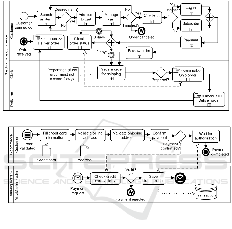
Figure 2: BPMN Business process model on high abstraction level, adapted from (Bousetta, El Beggar and Gadi, 2013 a).
Figure 3: BPMN expanded payment sub-process, adapted from (Bousetta, El Beggar and Gadi, 2013 a).
Then, a union of neighborhoods is get. This union
is the set X = [N] = {1, 2, 3, 4, 5, 6, 7, 8, 9, 10, 11, 12,
13, 14, 41, 42}. So TFM does not contain functional
feature 15, and this functional feature is considered to
be out of bounds of web shop’s system.
The set M is contains inputs and outputs (Asnina
and Osis, 2011). Set of inputs = {1}. Set of outputs =
{9, 13, 41, 42}. In this TFM, the main functional
cycle is as follows: 2-3-4-7-10-8-12-14-2 (Figure 1).
Figure 2 represents the BPMN business process
model on high level of abstraction that is given in
CIM-BPMN approach case study. This model
corresponds to topological space shown in Figure 1.
3.3 Increasing the Level of Detail
We need to expand functionality of the following
processes: order checkout and payment. To do this,
we can use a formal mechanism provided by
topological modeling – continuous mapping. If some
more detailed functioning system is formed by
substitution of a subset of specialized functional
features for some functional feature, then continuous
mapping exists between a detailed model and a
simplified parent topological model. In the
topological digraph G* (X*, U*), the direction of
arcs, which join the specialized point subset nodes
with other nodes, is determined by the direction of the
arcs, which join the replaced point with the
corresponding nodes of the digraph G (X, U) (Osis
and Asnina, 2011 c), (Osis, 1969). To put it simply,
continuous mapping allows substituting a subset of
functional features with a more detailed subset, and
vice versa.
MDI4SE 2016 - Special Session on Model-Driven Innovations for Software Engineering
342

Figure 4: Topological space part that represents detailed
functionality of checkout sub-process.
Figure 4 shows the part of topological space that
represents detailed functionality of checkout. This
part of TFM has been obtained by applying
continuous mapping. A subset of functional features
“7 Checking out an order”, “10: Logging in with a
web surfer’s account” and “11: Registering a new
web surfer’s account” is continuously mapped onto
the set of functional features that is represented in
Figure 4. Also, all cause-effect relations with
surrounding functional features, i.e., “4: Managing a
cart” and “8: Paying for an order”, are retained. Since
all functional features in Figure 4 belong to system’s
inner functional features, they also belong to set X of
web shop’s TFM. By increasing the level of detail, we
came up with a new precondition for functional
feature “8: Paying for an order” – [if order validation
is successful].
Figure 5: Topological space part that represents detailed
functionality of payment sub-process.
Figure 5 illustrates the part of topological space
that represents detailed functionality of payment.
Functional feature “8: Paying for an order” is
continuously mapped to the represented set.
Functional feature “27: Validating an order” is used
instead of “10: Logging in with a web surfer’s
account” to conform to the more detailed
functionality description of the checkout (see Figure
4). Not all functional features belong to the set of
system’s inner functional features (set N
Payment
).
X
Payment
= [N
Payment
] = {4, 12, 13, 27, 29, 30, 31, 32,
33, 34, 35, 36, 40, 42}. So TFM does not contain
functional features {37, 38, 39}, and they are
considered to be out of bounds of web shop’s system
(they are realized by a banking system).
Figure 3 displays a BPM of the expanded payment
sub-process. (Bousetta, El Beggar and Gadi, 2013 a)
also contains a BPM of the expanded checkout sub-
process. We do not include it since it is not required
for the comparison and to save space.
The main difference between the approaches
concerning the expansion of sub-processes is the
following. In TFM, the formal operation is used –
continuous mapping. The new subset must keep all
cause-effect relations that the substituted subset had
with other functional features in TFM. In BPMN,
there is no such strict rule. Therefore an ambiguity
may arise in BPMN model. Let’s consider a case
when the payment is rejected by banking system
(payment expansion). Low-level BPM model (see
Figure 3) does not make it clear what should happen
after the payment rejection, and high-level BPM (see
Figure 2) also does not help. In TFM there is no such
ambiguity. High-level TFM (see Figure 1) tells us
nothing about payment rejection, so the rejection
must be handled by a subset of functional features that
substitutes “8: Paying for an order”. Figure 1 shows
us a cause-effect relation between “8: Paying for an
order” and “4: Managing a cart”, and this relation
must be retained in the expanded TFM. After the
payment rejection, it makes sense to give web surfer
an opportunity to fill credit card information once
again, or to go back to cart management. In Figure 5,
after “36: Rejecting a payment” an execution goes to
“31: Filling in the information of a credit card”. Web
surfer can refill data or skip this step. During
validation of billing and shipping addresses (features
32 and 33) web surfer can go back to “4: Managing a
cart”. Therefore, processing of payment will be
cancelled. So dealing with the payment rejection is
explicitly and unambiguously described. We see that
formalism of TFM helps to achieve consistency
between abstract and detailed models.
3.4 Transformation to PIM: Class
Diagram
TFM4SE defines formal transformation from TFM to
Topological class diagram. It is called “topological”
because the UML metamodel of this diagram is
extended by integrating topological relations. By
adding topological relations mathematical formalism
is introduced to UML Class diagram (Osis and
Donins, 2010).
The main idea of the transformation is that the
functionality of each functional feature must be
realized by an individual class method. Before
executing the transformation, for each functional
feature we must come up with name of a class and
name of a method which will realize the functional
feature (Osis and Donins, 2010). We do not assign
Comparison of Topological Functioning Model for Software Engineering with BPMN Approach in the Context of Model Driven
Architecture
343
classes and methods to functional features that are not
realized by the information system. Examples are
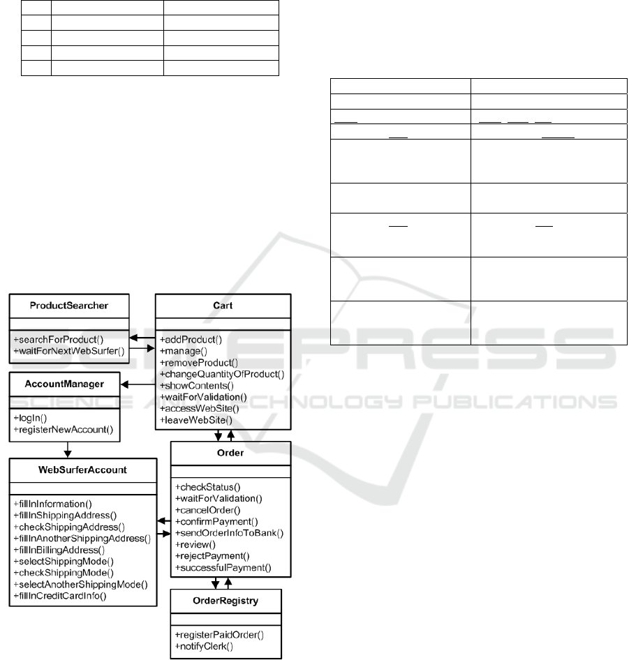
given in Table 2.
Table 2: Examples of class and method names.
ID Class Method
1 Cart accessWebSite()
2 ProductSearcher searchForProduct()
19 WebSurferAccount fillInInformation()
30 OrderRegistry notifyClerk()
Then, the formal transformation is executed (Osis
and Donins, 2010). All vertices of TFM with the same
class names should be merged, and while merging all
relationships between vertices should be kept. Since
this transformation is completely formal and does not
require participation of the architect, its automation
was proposed in (Solomencevs and Osis, 2015). The
resulting Topological class diagram is represented in
Figure 6. The arrows in the diagram are topological
relations. Guidelines for increasing the level of detail
of the obtained Topological class diagram are
published in (Donins et al., 2011).
Figure 6: Topological class diagram obtained from TFM.
In CIM-BPMN approach, the list of Business
rules needs to be defined. Business rules should focus
only on structural assertions: define structure,
relationships and the integrity constraints on data.
This type of Business rules is based on two concepts:
Term and Fact. A term is a word, phrase, or
sentence(s) which has a specific meaning for the
business. Facts are used for asserting an association
between two or more terms 'fact relating term'. Facts
connect things in the business (Bousetta, El Beggar
and Gadi, 2013 a). Authors introduce a template how
to formally describe a business rule (see Table 3).
Table 3: The proposed template for businesses rules,
adapted from (Bousetta, El Beggar and Gadi, 2013 a).
Template Example(s)
Term
Exam, Student, Response
Fact pass, own, use
<Term> <fact> <term> The student passes an exam
<Term> is characterized
by its <term>, <term>…
An exam is characterized by
a date of exam, a duration
and a set of questions
<Term> belongs to
one/many <term>
An exam belongs to one
category
<Term> <fact>
a/an/many/number
<term>
A question has four
responses.
<Term> may/can be a
<term1> or <term2>
An exam can be Multiple
Choice Question or a
direct questions
<Term> has number/ is
types: <term1>,
<term2>…
An exam has two types:
Multiple Choice Question,
direct questions
Concerning the case study, the following business
rules are defined (Bousetta et al., 2013a).
BR1: A customer passes many orders.
BR2: An order concerns at least one product.
BR3: An order has a billing address and a
shipping address.
BR4: Product belongs to one category.
BR5: Product is characterized by a reference,
description and a price.
BR6: A customer is characterized by a code, first
name, last name, an email address.
BR7: An order has a status.
BR8: An order is characterized by a date and
reference.
BR9: For each item in the cart we specify the
quantity.
BR10: A customer has an account.
BR11: An account is characterized by a login,
password and role.
BR12: An order has a payment.
BR13: A payment indicates a credit card and an
amount.
BR14: A credit card is characterized by a number,
validity date.
BR15: An order has a shipping mode.
BR16: A customer can review order.
BR17: A customer can cancel the order.
MDI4SE 2016 - Special Session on Model-Driven Innovations for Software Engineering
344
When business rules are defined, it is possible to
obtain the Domain class diagram.
Data objects from low-level BPMs (see Figure 7)
are considered to be terms and are mapped to classes
or attributes in Domain class diagram. This diagram
is completed with the different terms and facts
deduced from the Business rules according to the
mapping rules presented in Table 4.
Table 4: Mapping of Business rules to Domain class
diagram, adapted from (Bousetta et al., 2013 a).
Expression Meaning
Nouns, roles, concepts
…are considered as terms =>
Class.
This, these, that, those,
… and synonyms
Same term.
Its, his, her, their…
Express a relation between
two concepts. The term is an
attribute of the owner term if
it is a simple property
(atomic); otherwise it is a
class (if it is not simple)
List, set of
An ordered constrains in
OCL.
The verbs: belongs,
composed, contains,
include…
…are considered as a fact that
means an association of
composition or aggregation.
Many, a, an, any,
several, a lot of, one,
numbers, plural …
Multiplicity in an association.
Is..., Or…, may/can
be..., or…
Express a generalization /
specialization relationship.
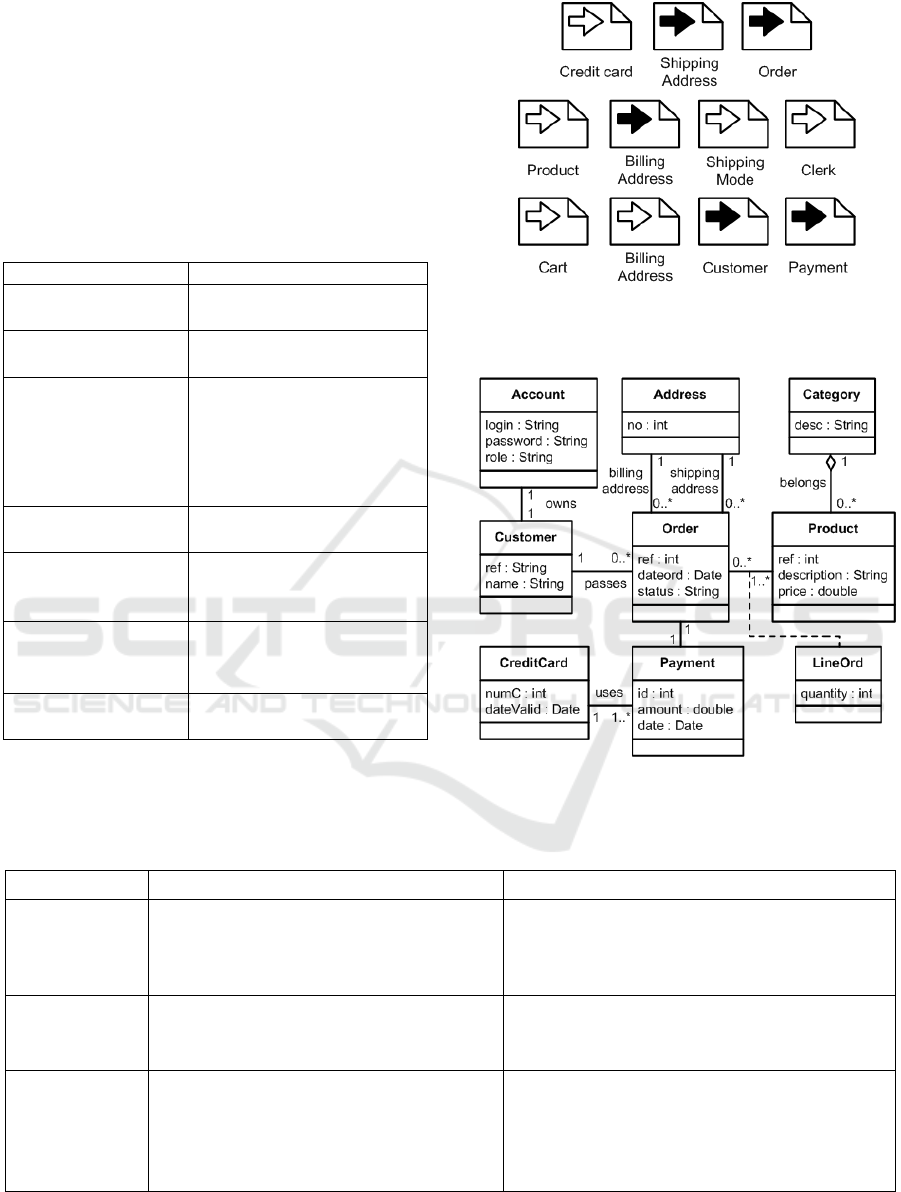
Figure 8 shows the obtained Domain class diagram
after the transformation.
Figure 7: Input/output data objects of the case study,
adapted from (Bousetta, El Beggar and Gadi, 2013 a).
Figure 8: Domain class diagram, adapted from (Bousetta,
El Beggar and Gadi, 2013 a).
Table 5: Comparison summary between TFM4SE and CIM-BPMN approaches.
TFM4SE (Osis et al.) CIM-BPMN (Bousetta et al.)
Business model
TFM.
Formal guidelines how to get TFM from
system's verbal description. Comprehensive
verbal description is needed.
BPMN high-level and low-level BPMs.
No formal guidelines for creating the model.
Comprehensive verbal description is not needed,
but knowledge is still required.
Increasing the
level of detail of
business model
Formal operation – continuous mapping –
ensures consistency between abstract and
detailed models.
Expanding the sub-process is done rather intuitively
which may lead to inconsistency with more abstract
model.
Transformation
to class diagram
Model has topological relations and methods;
does not have attributes.
Requires coming up with names for classes and
methods for each TFM’s functional feature.
Participation of architect is not required.
Model has standard UML relations (associations,
generalizations, aggregations and compositions),
multiplicities and attributes; does not have methods.
Requires formal definitions of Business rules.
Partial participation of architect is required.
Comparison of Topological Functioning Model for Software Engineering with BPMN Approach in the Context of Model Driven
Architecture
345

The differences between the approaches
concerning the obtaining of class diagram are the
following. TFM4SE requires additional effort in
coming up with names of classes and methods that
will realize the functional features. Additional effort
in CIM-BPMN approach is expressed in defining
Business rules. In TFM4SE, the transformation does
not require user participation and can be fully
automated. In CIM-BPMN, as we understood from
studying the examples, it partly requires user
participation, and can be semi-automated. The
obtained resulting models differ. In case of TFM4SE,
classes with methods and without attributes are
created. There are topological relations between
classes. In its turn CIM-BPMN provides creation of
classes with attributes and without methods, and there
are standard UML relations between classes:
associations, generalizations, aggregations,
compositions, and also multiplicities. So, Topological
class diagram focuses on separation of
responsibilities between classes, and Domain class
diagram reflects the structure in more detail.
4 CONCLUSIONS
The discussion in this paper was directed to the
comparison of TFM4SE with model driven
approaches that use BPMN for CIM modeling and
provide CIM → PIM transformation. From the
discovered ones we have chosen the most well-
elaborated to compare it with TFM4SE concerning
CIM modeling and transformation to class diagram
on PIM level. The comparison was performed on
basis of an example (case study). The result of the
work is summarized in Table 5.
As we emphasized in the introduction, the main
difference between TFM and BPMN model is that
TFM is a mathematically formal model, and BPMN
is not. We believe that the improvement of the object-
oriented system analysis and modelling lays in using
formal methods. We were interested in finding out
what benefits and what drawbacks does the formalism
of TFM bring in comparison to CIM-BPMN
approach. Let’s start with the drawbacks. More effort
must be put in the very early stage of software
development – the analysis. The comprehensive
description of the system must be developed.
Concerning transformation to PIM, the class diagram
lacks standard relations, multiplicities and attributes.
On the other hand, the advantages of TFM4SE are the
following. On CIM level, the consistency between
abstract and detailed models is ensured, because
formal operation for manipulating the level of detail
is applied. CIM → PIM class diagram transformation
is done rather easily. Besides TFM, it requires only
the names for classes and methods. Transformation
can be executed fully automatically. The obtained
class diagram contains methods and topological
relations.
Roughly simplifying the comparison results,
formalism of TFM brings more consistency between
models and allows obtaining class diagram that
divides the responsibilities between classes. These
advantages come at the cost of putting more effort
into CIM modeling.
In this paper we concentrated on approaches that
use BPMN, and on construction of class diagram. The
future research will cover transformations to other
models on PIM level; and approaches that also
provide CIM → PIM transformation, but use other
models on CIM level.
REFERENCES
Asnina, E., Gulbis, B., Osis, J., Alksnis, G., Donins, U.,
Slihte, A. 2011, Backward Requirements Traceability
within the Topology-based Model Driven Software
Development. In: Proceedings of the 3rd International
Workshop on Model-Driven Architecture and
Modeling-Driven Software Development (MDA &
MDSD 2011), China, Beijing, 7-11 June, 2011. Lisbon:
SciTePress, pp.36-45. ISBN 9789898425591.
Asnina, E., Osis, J. 2010, Computation Independent
Models: Bridging Problem and Solution Domains. In:
Proceedings of the 2nd InternationalWorkshop on
Model-Driven Architecture and Modeling Theory-
Driven Development (MDA & MTDD 2010), in
conjunction with ENASE 2010, Greece, Athens, 22-24
July, 2010. Lisbon: SciTePress, pp.23-32. ISBN
9789898425164.
Asnina, E., Osis, J. 2011, Topological Functioning Model
as a CIM-Business Model. In: Model-Driven Domain
Analysis and Software Development: Architectures and
Functions. Hershey, New York: IGI Global, pp. 40-64.
Available from: doi: 10.4018/978-1-61692-874-
2.ch003.
Bousetta, B., El Beggar, O., Gadi, T. 2013 a, A
methodology for CIM modelling and its transformation
to PIM. In: Journal of Information Engineering and
Applications, Vol.3, No.2, pp 1-21. ISSN 2224-5782
(print). ISSN 2225-0506 (online).
Bousetta, B., El Beggar, O., Gadi, T. 2013 b, Automating
Software Development Process: Analysis-PIMs to
Design-PIM Model Transformation. In: International
Journal of Software Engineering and Its Applications,
Vol.7, No.5, SERSC, pp. 167-196. ISSN 1738-9984.
Bousetta, B., El Beggar, O., Gadi, T. 2013 c, Generating
operations specification from domain class diagram
using transition state diagram. In: International Journal
MDI4SE 2016 - Special Session on Model-Driven Innovations for Software Engineering
346

of Computer and Information Technology (IJCIT).
Volume 2, Issue 1, January 2013, pp. 29-36. ISSN:
2279 – 0764.
Castro, V.D., Marcos, E., Vara, J.M. 2011, Applying CIM-
to-PIM model transformations for the service-oriented
development of information systems. Information and
Software Technology. January 2011, Volume 53, Issue
1, pp. 87-105.
Donins, U., Osis, J., Slihte, A., Asnina, E., Gulbis, B. 2011,
Towards the Refinement of Topological Class Diagram
as a Platform Independent Model. In: Proceedings of
the 3rd International Workshop on Model-Driven
Architecture and Modeling-Driven Software
Development (MDA & MDSD 2011), China, Beijing, 8-
11 June, 2011. Lisbon: SciTePress, pp.79-88. ISBN
9789898425591.
El Beggar, O., Bousetta, B., Gadi, T. 2012 a, Generating
methods signatures from transition state diagram: A
model transformation approach. In: Information
Science and Technology (CIST), 22-24 Oct. 2012. pp.4-
9. Available from: doi: 10.1109/CIST.2012.6388054.
El Beggar, O., Bousetta, B., Gadi, T. 2012 b, Automatic
code generation by model transformation from
sequence diagram of system’s internal behavior. In:
International Journal of Computer and Information
Technology (IJCIT), November 2012, Volume 1, Issue
2, pp. 129-146. ISSN: 2279 – 0764.
Fazziki, A.E., Lakhrissi, H., Yetognon, K., Sadgal, M.
2012, A Service Oriented Information System: A
Model Driven Approach. In: The Eighth International
Conference on Signal Image Technology and Internet
Based Systems (SITIS), Naples, 25-29 November, 2012,
IEEE, pp.466-473,. ISBN 978-1-4673-5152-2.
Gutierrez, J.J., Nebut, C., Escalona, M.J., Mejias, M.,
Ramos, I.M. 2008, Visualization of Use Cases through
Automatically Generated Activity Diagrams. In:
Proceedings of 11th International Conference,
MoDELS 2008, Toulouse, France, September 28 -
October 3, 2008. Berlin, Heidelberg: Sprienger, pp. 83-
96. ISBN 978-3-540-87874-2. e-ISBN 978-3-540-
87875-9.
Hahn, C., Panfilenko, D., Fischer, K. 2010, A Model-
Driven Approach to Close the Gap between Business
Requirements and Agent-Based Execution. In:
Proceedings of the 4th Workshop on Agent-based
Technologies and applications for enterprise
interOPerability, Toronto, Canada, 10 May 2010.
AAMAS 2010, Toronto, Canada, pp. 13-24.
Kherraf, S., Lefebvre, E., Suryn, W. 2008, Transformation
from CIM to PIM Using Patterns and Archetypes. In:
19th Australian Conference on Software Engineering,
ASWEC 2008, Perth, Australia, 26-28 March 2008.
IEEE, pp.338-346. ISBN 978-0-7695-3100-7. ISSN
1530-0803. Available from: doi:
10.1109/ASWEC.2008.4483222.
Kardos, M., Drozdova, M. 2010, Analytical method of CIM
to PIM transformation in Model Driven Architecture
(MDA). Journal of Information and Organizational
Sciences (JIOS). Vol. 34, Issue 1, pp 89-99. ISSN 1846-
3312. e-ISSN 1846-9418.
Mazon, J., Pardillo, J., Trujillo, J. 2007, A Model-Driven
Goal-Oriented Requirement Engineering Approach for
Data Warehouses. In: Proceedings of ER 2007
Workshops CMLSA, FP-UML, ONISW, QoIS,
RIGiM,SeCoGIS, Auckland, New Zealand, November 5-
9, 2007
. Berlin, Heidelberg: Sprienger, pp. 255-264.
ISBN 978-3-540-76291-1. e-ISBN 978-3-540-76292-8.
Miller, J., Mukerji, J. 2003, MDA Guide Version 1.0.1,
OMG, viewed 10 September 2015,
<www.omg.org/cgi-bin/doc?omg/03-06-01>OMG
(Object Management Group) 2012, Service oriented
architecture Modeling Language (SoaML)
Specification, Version 1.0.1, viewed 10 January 2016,
<www.omg.org/spec/SoaML/1.0.1/PDF/>
OMG (Object Management Group) 2013, Business Process
Model and Notation (BPMN), Version 2.0.2, viewed 8
January 2016, <www.omg.org/spec/BPMN/2.0.2/PDF>
OMG (Object Management Group) 2015, OMG Unified
Modeling LanguageTM (OMG UML), Version 2.5,
viewed 8 January 2016, <www.omg.org/spec/UML/2.5
/PDF>
Osis, J. 1969, Topological Model of System Functioning (in
Russian). In: Automatics and Computer Science, J. of
Academia of Siences, Riga, Latvia, Nr. 6, pp. 44-50.
Osis, J. 2004, Software Development with Topological
Model in the Framework of MDA. In: Proceedings of the
9
th
CAiSE/IFIP8.1/EUNO International Workshop on
Evaluation of Modeling Methods in Systems Analysis and
Design (EMMSAD’2004) in connection with the
CAiSE’2004. Volume 1, RTU, Riga, pp. 211-220.
Osis, J., Asnina, E. 2011 a, Is Modeling a Treatment for the
Weakness of Software Engineering? In: Model-Driven
Domain Analysis and Software Development:
Architectures and Functions. Hershey, New York: IGI
Global, pp. 1-14. Available from: doi: 10.4018/978-1-
61692-874-2.ch001.
Osis, J., Asnina, E. 2011 b, Derivation of Use Cases from
the Topological Computation Independent Business
Model. In: Model-Driven Domain Analysis and
Software Development: Architectures and Functions.
Hershey, New York: IGI Global, pp. 65-89.
Osis, J., Asnina, E. 2011 c, Topological Modeling for
Model-Driven Domain Analysis and Software
Development: Functions and Architectures. In: Model-
Driven Domain Analysis and Software Development:
Architectures and Functions. Hershey, New York: IGI
Global, pp. 15-39.
Osis, J., Asnina, E., Donins, U., Garcia-Diaz, V. 2014,
Dependencies among Architectural Views Got from
Software Requirements Based on a Formal Model. In:
Applied Computer Systems. Vol.16, pp.5-12. ISSN
2255-8683. e-ISSN 2255-8691.
Osis, J., Asnina, E., Grave, A. 2007, MDA Oriented
Computation Independent Modeling of the Problem
Domain. In: Proceedings of the 2nd International
Working Conference on Evaluation of Novel
Approaches to Software Engineering (ENASE 2007),
Spain, Barcelona, 23-25 July, 2007. Barcelona:
INSTICC Press, pp.66-71. ISBN 978-989-8111-10-4.
Comparison of Topological Functioning Model for Software Engineering with BPMN Approach in the Context of Model Driven
Architecture
347

Osis, J., Asnina, E., Grave, A. 2008 a, Formal Problem
Domain Modeling within MDA. In: Communications in
Computer and Information Science (CCIS). Software
and Data Technologies: Second International
Conference ICSOFT/ENASE 2007: Revised Selected
Papers, Germany, Berlin, 22-25 July, 2007. Berlin:
Springer-Verlag Berlin Heidelberg, pp.387-398. ISBN
9783540886549. e-ISBN 9783540886556. ISSN 1865-
0929.
Osis, J., Asnina, E., Grave, A. 2008 b, Computation
Independent Representation of the Problem Domain in
MDA. In: e-Informatica Software Engineering Journal,
Vol.2, Iss.1, pp. 29-46. ISSN 1897-7979.
Osis, J., Donins, U. 2010, Formalization of the UML Class
Diagrams. In: Evaluation of Novel Approaches to
Software Engineering: 3rd and 4th International
Conferences ENASE 2008/2009: Revised Selected
Papers, Italy, Milan, 9-10 May, 2009. Berlin: Springer-
Verlag, pp.180-192. ISBN 9783642148187. e-ISBN
9783642148194. ISSN 1865-0929.
Osis, J., Slihte, A. 2010, Transforming Textual Use Cases
to a Computation Independent Model. In: Model-
Driven Architecture and Modeling Theory-Driven
Development: Proceedings of the 2nd International
Workshop (MDA & MTDD 2010), Greece, Athens, 22-
24 July, 2010. Lisbon: SciTePress, pp.33-42. ISBN
9789898425164.
Rhazali, Y., Hadi, Y., Mouloudi, A. 2014, Transformation
Method CIM to PIM: From Business Processes Models
Defined in BPMN to Use Case and Class Models
Defined in UML. In: World Academy of Science,
Engineering and Technology – International Journal of
Computer, Electrical, Automation, Control and
Information Engineering, Vol:8, No:8.
Rodriguez, A., Garcia-Rodriguez de Guzman, I., Fernandez
Medina, E., Piattini, M. 2010, Semi-formal
transformation of secure business processes into analysis
class and use case models: An MDA approach.
Information and Software Technology. September 2010,
Volume 52, Issue 9, pp. 945-971. ISSN 0950-5849.
Slihte, A., Osis, J., Donins, U. 2011, Knowledge Integration
for Domain Modeling. In: Proceedings of the 3rd
International Workshop on Model-Driven Architecture
and Modeling-Driven Software Development (MDA &
MDSD 2011), China, Beijing, 8-11 June, 2011. Lisbon:
SciTePress, pp.46-56. ISBN 9789898425591.
Slihte, A., Osis, J., Donins, U., Asnina, E., Gulbis, B. 2011,
Advancements of the Topological Functioning Model
for Model Driven Architecture Approach. In:
Proceedings of the 3rd International Workshop on
Model-Driven Architecture and Modeling-Driven
Software Development (MDA & MDSD 2011), China,
Beijing, 7-11 June, 2011. Lisbon: SciTePress, pp.91-
100. ISBN 9789898425591.
Solomencevs, A., Osis, J. 2015, The Algorithm for Getting
a UML Class Diagram from Topological Functioning
Model. In: Proceedings of 10th International
Conference on Evaluaton of Novel Approaches to
Software Engineering, Spain, Barcelona, 29-30 April,
2015. Portugal: SciTePress, pp.341-351. ISBN 978-
989-758-100-7.
Yu, E. 1995, Modelling Strategic Relationships for Process
Reengineering. PhD thesis. University of Toronto,
Canada. 124 p.
Zhang, W., Mei, H., Zhao, H., Yang, J. 2005,
Transformation from CIM to PIM: A Feature-Oriented
Component-Based Approach. In: Proceedings of 8th
International Conference, MoDELS 2005, Montego
Bay, Jamaica, October 2-7, 2005. Berlin, Heidelberg:
Sprienger, pp. 248-263. ISBN 978-3-540-29010-0. e-
ISBN 978-3-540-32057-9.
MDI4SE 2016 - Special Session on Model-Driven Innovations for Software Engineering
348
