
Verification of BPMN Model Functional Completeness by using the
Topological Functioning Model
Erika Nazaruka, Viktoria Ovchinnikova, Gundars Alksnis and Uldis Sukovskis
Department of Applied Computer Science, Riga Technical University, Sētas iela 1, Riga, Latvia
Keywords: BPMN, Model Verification, Completeness, Topological Functioning Model.
Abstract: BPMN (Business Process Model and Notation) models are used to specify business knowledge in the
language that is familiar for business people. They consist of multiple process diagrams that highlight
different aspects of interaction among participants. Verification of BPMN models is important since
graphical fragmentary presentation could be a source of errors such as incompleteness, deadlocks, livelocks,
incorrect terminations etc. We consider verification of model completeness. The model is transformed to the
topological functioning model (TFM) in order to check completeness of inputs, outputs and functioning
cycles of the entire specified system. The proposed approach is dedicated to the verification of the model at
the beginning of analysis, and it could be supplemented by other methods at the design stage. This approach
is more dedicated to analysis of the whole system, than to the verification of the concrete fragment work.
1 INTRODUCTION
Business Process Model and Notation (BPMN) is a
standard of a business process graphical notation
that allows presenting business process steps from
the start to the end (Object Management Group,
2015). This has its advantages, namely, a business
analyst can depict all steps of a business process,
showing manual and automated steps, dependencies
among them, data flows, step flows by business
units etc. However, each process is only a fragment
of the entire business that may have dozens of such
processes. The question is how to check the
correctness of each of them, correctness of
dependencies among them, and completeness of
them.
The verification of business process
specifications usually uses informal techniques, such
as workshops, where stakeholders can determine and
show possible issues in the defined processes
(Falcioni et al., 2012). However, in some cases
specifications may be simulated and formally
verified. Formal verification allows discovering of
unwanted behavior and situations, however, this
requires derivation of formal model from informal
business process specifications (Falcioni et al.,
2012).
In this research we consider a formal
mathematical model, the Topological Functioning
Model (TFM), based on principles of the system
theory and algebraic topology. It specifies the
system in a holistic manner, showing its interaction
with the external systems and inner functionality at
the high level of abstraction.
The research objective is to understand
advantages and limitations of TFM application for
verification of completeness of BPMN processes. In
other words, the obtained results should clear what
aspects the TFM can help to verify unlike other
formal models such as Petri Nets, YAWL, or
temporal logic. As other author work showed,
analysis of the completeness of BPMN models, i.e.
whether they specify the domain under the discourse
completely, is not solved enough.
In order to achieve the research goal, we have
defined mappings from BPMN model elements to
the TFM elements and discussed the verification of
BPMN model completeness, illustrating the process
on the example.
The paper is organized as follows. Section 2
describes related work on BPMN process
verification. Section 3 describes elements of BPMN
models and the TFM as well as mappings between
them in brief. Section 4 illustrates application of the
TFM for BPMN process verification and states main
results. Conclusion summarizes advantages and
limitations of the TFM application based on the
research results.
Nazaruka, E., Ovchinnikova, V., Alksnis, G. and Sukovskis, U.
Verification of BPMN Model Functional Completeness by using the Topological Functioning Model.
In Proceedings of the 11th International Conference on Evaluation of Novel Software Approaches to Software Engineering (ENASE 2016), pages 349-358
ISBN: 978-989-758-189-2
Copyright
c
2016 by SCITEPRESS – Science and Technology Publications, Lda. All rights reserved
349

2 RELATED WORK
Although verification of BPMN models is not a new
topic, it is still actual. BPMN model verification is
based on mappings into other, more formal,
languages, e.g. into programming languages such as
Java and Prolog, formal languages such as
PROMELA, Petri Nets, CSP (Communicating
Sequential Processes), timed and process automata,
and into mathematical languages such as temporal
logic.
In (Falcioni et al., 2012), authors indicated that a
usage of formal languages (e.g., Petri Nets or
Process Algebra) as a target language in mappings
from BPMN specifications may lead to the loss of
some concepts and verification from those aspects
may be impossible. Another side effect of using
formal languages as a target may be verification of
unnecessary aspects that are native for those
languages. In order to deal with such issues, the
authors suggested using a Java model and an
unfolding technique based verification approach for
business processes depicted in the BPMN 2.0
collaboration diagrams. This approach is
implemented as an Eclipse plug-in and applied for
several real scenarios. The authors noted that their
approach reduces problems of state explosion and
implementation/respect of synchronization policies
of the target language. The interesting “side-effect”
is discovering of the collaboration “anti-patterns”.
Another interesting approach is a use of Prolog
language (Ligeza et al., 2012) in order to check the
correctness of data flows by using declarative
specification of the BPMN model.
In (Solaiman et al., 2015) the authors suggested
automated transformation into PROMELA, the input
language of the SPIN model checker, in addition
applying also Linear Temporal Logic for verification
of correctness properties (in other words, logical
sequence). PROMELA is also a choice of authors in
(Yamasathien and Vatanawood, 2014), where
BPMN models are verified via workflow pattern
transformations. The SPIN tool is mature enough to
be used for verification of multi-threaded software
applications (SPIN, 2015). As the authors noted,
SPIN can verify safety and liveness properties of
abstract models. The main issue that the authors
meant is identification of semantically independent
common correctness requirements for their
verification by default, i.e. such principles as
connectedness, well-threadedness, and coherence.
Another formal model that is widely used is a
Petri net. Petri nets (Universität Hamburg, 2015) is a
formal language for modeling parallel and
concurrent execution of the system. They can be
used for verification of compensations and
transactions in BPMN models (Takemura, 2008),
time properties when the execution time of web
services is not known (Huai et al., 2010) and others.
Authors in (Flavio et al., 2010) proposed
transforming BPMN models to CSP formal language
in order to use benefits of CSP verification via
model checking. In contrast to the previous work,
they omitted “few constructs dealing with
transactions, such as compensation events and
cancel events, or time”. Their main goal is
measuring quality of services in order to verify the
efficiency of specified business processes.
Another formal languages that can be used for
BPMN model verification are Timed Automata (TA)
and Process Automata (PA). The author in (Morales,
2013) suggests transformation to TA-networks in
order to verify controllability of BPMN models, i.e.
“correctness against requirements expressed in
temporal logic”. The author also (as we do) suggests
grouping all partial behaviors in order to get the
complete participant’s view. After that, the author
checks the completeness of those views. This differs
from our approach since we merge all participant
behaviors into one model. In their turn, authors in
(Tantitharanukul et al., 2010) verify deadlocks and
multiple terminations in BPMN using PA.
In order to check deadlocks and soundness of
BPMN models, they could be transformed to YAWL
(Ye et al., 2008), that is a workflow language with
formal semantics.
BPMN models can be transformed into formal
specifications based on linear temporal logic (LTL)
and computation tree logic (CTL) that allows
checking such properties as safety, liveness, fairness,
invariant properties, and response properties (El
Hichami et al., 2014), deadlocks, livelocks and
multiple terminations (Kherbouche et al., 2012).
Summarizing, most of proposed formal
techniques are used for verification of such
important model properties as deadlocks, thread
correctness, data flows, correct termination etc. The
completeness of the model in system-theoretical
viewpoint is attempted to be solved only in
(Morales, 2013). The difference is that we consider
the completeness of inputs, outputs and functioning
cycles instead of completeness form a concrete user
perspective.
MDI4SE 2016 - Special Session on Model-Driven Innovations for Software Engineering
350

3 VERIFICATION OF THE TFM
TRANSFORMED FROM THE
BPMN MODEL
3.1 The TFM in Brief
The TFM is a formal mathematical model that has
been proposed at Riga Technical University (RTU),
Latvia, by Janis Osis in 1969. At that time this
model has been dedicated for mathematical
specification of functionality of complex mechanical
systems (Osis and Asnina, 2011).
The TFM represents system functionality in a
holistic manner from a computation independent
viewpoint (Asnina and Osis, 2011c). It describes the
functional and structural aspects of the software
system in the form of a directed graph. The digraph
vertices depict functional characteristics of the
system named in human understandable language,
while edges depict causal relations between them.
Such specification is more perceived, precise and
clear then the large textual descriptions.
A TFM is a topological space (X, Q), where X is
a set of functional features and Q is a set of
relationships between elements in X (Osis and
Asnina, 2011b). The composition of the TFM is
presented in (Osis and Asnina, 2011).
A functional feature represents some system’s
functional characteristic, e.g., a business process, a
task, an action, or an activity (Osis and Asnina,
2011a). It can be specified by a unique tuple <A, R,
O, PrCond, PostCond, Pr, Ex>, where (Osis and
Asnina, 2011b):
A is object’s action,
R is a set of results of the object’s action (it is
an optional element),
O is an object that gets the result of the action
or a set of objects that are used in this action,
PrCond is a set of preconditions or atomic
business rules,
PostCond is a set of post-conditions or atomic
business rules,
Pr is a set of feature’ providers, i.e. entities
(systems or sub-systems) which provide or
suggest an action with a set of certain objects,
Ex is a set of executors (direct performers) of
the functional feature, i.e. a set of entities
(systems or sub-systems) which enact a
concrete action.
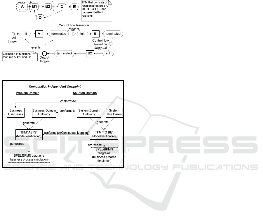
The cause-and-effect relations between
functional features define the cause from which the
triggering of the effect depends (Figure 1).
The formal definition of the cause-and-effect
relations and their combinations are given in (Asnina
and Ovčiņņikova, 2015) and are as follows:
1) Formal definition of a cause-and-effect
relation: A cause-and-effect relation T
i
is a binary
relationship that relates exactly two functional
features X
c
and X
e
. Both X
c
and X
e
may be the same
functional feature in case of recursion. Each cause-
and-effect relation is a unique 5-tuple (1).
T
i
= <ID, X
c
, X
e,
N, S>, where (1)
ID is a unique identifier of a relation;
X
c
is a cause functional feature;
X
e
is an effect functional feature;
N is a Boolean value of the necessity of X
c
for
generating X
e
(default value is true);
S is a Boolean value of the sufficiency of X
c
for generating X
e
(default value is true).
2) Formal definition of a logical relation: A
logical relation L
i
specifies the logical operator
conjunction (AND), disjunction (OR), or exclusive
disjunction (XOR) between two or more cause-and-
effect relations T
i.
The logical relation denotes
system execution behavior (e.g., decision making,
parallel or sequential actions). Each logical relation
is a unique 3-tuple (2).
L
i
= <ID, T, R
T
>, where (2)
ID is a unique identifier of a relation;
T is a set of cause-and-effect relations
{T
i
, ..., T
n
}
that participate in this logical
relation;
R
T
is a logical operator AND, OR, or XOR
over T; the default values is operator OR.
The execution of the functional feature instance
is illustrated in Figure 1. After triggering the
instance is initiated, then executed and terminated.
In case of successful execution its termination leads
to triggering the initiation of the next (effect)
functional feature instances. In case of failure, the
triggering will not occur.
The TFM is characterized by the topological and
functioning properties (Osis and Asnina, 2011a).
The topological properties are connectedness,
neighborhood, closure and continuous mapping. The
functioning properties are cause-and-effect relations,
cycle structure, inputs and outputs.
Rules of composition and derivation processes of
the TFM from the system description is provided by
examples and described in detailed in (Asnina,
2006), (Osis et al., 2007), (Osis et al., 2008) and
(Osis et al., 2008). Construction of the TFM with
attention put on continuous mappings between
problem and solution domain is provided in (Asnina
and Osis, 2010). The TFM can also be generated
Verification of BPMN Model Functional Completeness by using the Topological Functioning Model
351
automatically from the business use case
descriptions, which can be specified in the IDM
toolset (Osis and Slihte, 2010), (Slihte et al., 2011),
(Slihte and Osis, 2014). It also can be manually
created in the TFM Editor from the IDM toolset.
Figure 1: The execution of the functional feature instance.
Figure 2: System analysis with the TFM as a start point.
The UML use case diagram can be obtained from
the TFM, according to (Osis and Asnina, 2011d),
(Donins, 2012). According to (Osis and Donins,
2010), (Donins et al., 2011) the TFM can be
manually (but according to the precise rules)
transformed into most used UML diagram types,
including UML Activity Diagrams and State Chart
Diagrams.
The TFM can be used as a formal blueprint of
the system functioning at the beginning of analysis
and then transformed to BPMN processes (Asnina,
2009). Such forward modeling and analysis allows
formal determination of system boundaries, system
completeness and causal dependencies between parts
of functioning (Figure 2). Depending on the analysis
context, business or system goals are criteria used
for model decomposition into BPMN processes.
3.2 BPMN Models in Brief
Let us look at communications between participants
defined according to the BPMN 2.0 standard (Object
Management Group, 2011) as well as at other
BPMN elements in brief.
There are three basic types of sub-models within
a complete BPMN model. The first type is Processes
(Orchestration) that includes the following sub-
types, namely, private non-executable and private
executable internal Business Processes as well as
public Processes. The second type is called
Choreography. And the third one is Collaborations.
The last type may include Processes and/or
Choreographies.
If we look at them from the viewpoint of defined
communications between participants, then we can
conclude the following. Communications within
BPMN sub-models exist in case of public Processes,
Choreographies, Collaborations and Conversations.
They are depicted as message flows (Message Flow)
or a set of message exchanges (Choreography)
between Participants (Pools). In case of
Conversation diagrams, message exchanges are
shown as Conversations (nodes and links). In other
words, flow elements are modeled as processes, but
the interaction between processes is modelled in
terms of Collaboration and Choreography.
As mentioned in (Object Management Group,
2011, pp. 127-128), a Message Flow depicts the
flow of communications (messages) between two
Participants. Messages can be sent and received.
The message can be depicted as a Choreography
Task in a Choreography. In a particular case of a
Collaboration diagram, namely, a Conversation
diagram, a Conversation may be shown as a set of
Message Flows.
Summarizing BPMN elements, they are business
or system actors represented by swim-lines (pools
and lanes); system activities that define business
system’ functionality represented by processes, sub-
processes, and tasks; decomposition of system
processes where processes can be divided to sub-
processes to tasks; system events that initiate
execution of functionality represented by start,
intermediate, and end events; connecting elements (a
sequence flow, message flow, and association) that
connect to each other such constructs as activities,
events and gateways; and, finally, gateways that
determine different decisions (forking, merging, and
joining of paths).
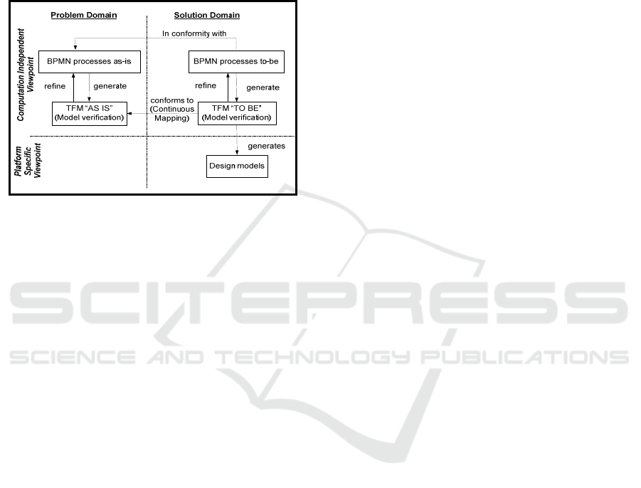
3.3 Mappings from BPMN to TFM
If BPMN models are used as a source of knowledge
instead of textual descriptions of business/system
use cases (Figure 3) than verification of the artifacts
MDI4SE 2016 - Special Session on Model-Driven Innovations for Software Engineering
352
become harder. Main issues in using BPMN
diagrams are their fragmentary nature and a large
number of modelling constructs in comparison with
simple graphical or structural textual scenarios. The
TFM as a formal start helps in avoiding these issues
due to TFM formalism, a minimal number of
modelling constructs and a holistic representation of
the domain under discussion (Asnina, 2009).
Figure 3: System Analysis with the BPMN model as a
start point.
Constructs of business process models and TFM
constructs are intended to describe behavior of the
system at the business process level, and, therefore,
these constructs can be mapped, if they have the
equal or similar semantics in the field of business
process modeling.
Table 1 illustrates mappings between BPMN and
TFM elements. In short, tasks, events and data
objects form TFM functional features. In their turn,
sequence and message flows (as well as
conversation and sub-conversation nodes) form
TFM cause-and-effect relations. And, the last,
gateways set logical operators on the combination of
outgoing or incoming cause-and-effect relations.
Such elements as Text Annotation, Category,
Message (decoration), ParticipantMultiplicity,
ParticipantAssociation, Conversation Link, Task
markers (loop, multi-instance, and compensation),
Compensation and Data Store have not any
corresponding notion in the TFM. We should note
that information of the multi-instance mode, looping
or canceling of BPMN processes or activities will be
lost in the result of such transformation.
Another aspect is that in the TFM information
about participants is held in the description of
functional features. Besides that participants may be
as providers as executors of the functional features.
By default it is assumed that participants are the
same as executors, since the other case is rare even
in BPMN models.
Such TFM element as a functioning cycle does
not have direct correspondence with any BPMN
elements. However, the cycle should be determined
after gluing all transformed BPMN diagrams.
The only BPMN diagram which transformation
may lead to the natural appearance of the
functioning cycles is the Conversation Diagram.
Transformation of other diagrams requires
understanding of the sequence and dependency
between each pair of them.
Summarizing, transformation from the BPMN to
the TFM raises the level of abstraction and allows
specifying processes holistically, thus, allowing
verification of completeness of process descriptions
from the functional point of view (that will be
discussed in the next sub-section).
3.4 Verification of the Obtained TFM
The verification of the obtained TFM consists of two
parts. The first one is structural verification, and the
second one is functional verification.
As mentioned in Section 3.1, the structurally
valid TFM must satisfy four topological and four
functioning properties, i.e. it is structurally valid if:
Has no isolated vertices,
Preserves continuous mapping among different
levels of abstraction,
Has functioning cycles,
Has inputs and outputs,
Has mathematically proved boarders, i.e.
contains only system’s functional features for
inner functioning and interaction with the
external systems.
The TFM is functionally valid if:
All cause-and-effect relations or their
combinations are necessary and sufficient in
order to trigger subsequent functional features.
Functioning cycles contain all the necessary
functional aspects in the order that is required
by the domain logic.
Both sets of inputs and outputs are complete.
Any incompliance with the mentioned
characteristics means that the BPMN model is not
complete or specifies the functional business logic
incorrectly. The incorrectness could be expressed as
absence of inputs or outputs as well as incorrect
cycles and paths in the obtained digraph.
Verification of BPMN Model Functional Completeness by using the Topological Functioning Model
353

Table 1: Mappings between BPMN and TFM elements.
BPMN element TFM element
Association A fact that Flow Object belongs to the artifact
Group (visualization) A group (visualization)
Text Annotation none
Category none
Message (decoration) none
Sequence Flow A cause-effect relation between functional features with the same executor
Collaboration,
Conversation (diagram)
A part of the topological space where executors of functional features are
different
Pool (Participant), PartnerEntity,
PartnerRole
An executor (or a provider) of the functional feature
ParticipantMultiplicity none
ParticipantAssociation none
Message Flow,
Conversation (node),
Sub-conversation (node)
A cause-and-effect relation between functional features with different
executors; conversation nodes must be expanded
Conversation Link none
Process (within pools), Sub-Process A part of the topological space where the same executor is set for all
functional features; process resources are functional features executors.
Lane (sub-partition within a Process) A part of the topological space where functional features are logically joined
in some set according to some purpose
Choreographies (between pools) A part of the topological space; however, information of the sender and
recipient is split among functional features
Activity (atomic) or Task An action with the object/result of the functional feature; a resource of the
activity is an executor of the functional feature (or a provider)
Task marker (loop, multi-instance,
compensation)
none
Service Task, User Task, Manual Task,
Business Rule Task, Script Task
An action with the object/result of the functional feature
Send Task A cause functional feature in the cause-effect relation where functional
features with different executors take part
Receive Task An effect functional feature in the cause-effect relation where functional
features with different executors take part
Activity (non-atomic) A set of functional features
Performer An executor of the functional feature
Start Event An indicator of initialization of the input/cause functional feature; timer,
conditional and signal start events contain preconditions for triggering the
functional feature
End Event An indicator of finishing the output/effect functional feature; the end event
may contain the post-condition of the functional feature
Middle Event An indicator of triggering the functional feature; in case of catching events it
may indicate the input functional feature or the precondition of the triggered
functional feature; link events indicate the cause (source) and the effect
(target) functional features in the cause-effect relations
Gateway;
Event-Based Gateway
A decision node that is expressed as logical operators in combination of
cause-and-effect relations; exclusive gateways are equal to operator XOR;
inclusive gateways are equal to OR; parallel gateways are equal to AND;
complex gateways are equal to decision tables assigned to the combination of
outgoing cause-effect relations.
Compensation none
Data Object,
Data Object Reference
An object or a result of the functional feature; however, the collection may be
expressed using only the plural form of the noun
Data Store none
Data Association An indicator to which functional feature the object belongs
MDI4SE 2016 - Special Session on Model-Driven Innovations for Software Engineering
354
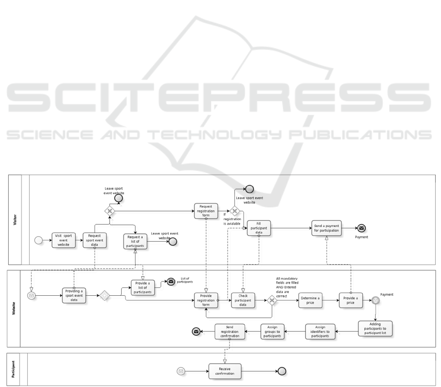
4 THE EXAMPLE
4.1 Domain Description
Let us take as an example a system for sport event
organization. Let us call it “Registration at the sport
event”. A short version of the systems description is
as follows: “The visitor may visit and leave the sport
event website after doing some tasks in the website.
He/she may request sport event data and after that
the website returns the requested data to the visitor.
The visitor may request the list of participants and
see all participants in the list or may request a
registration form, register to the sport event and fill
participant data. When participant’s data is added it
needs to be checked. If participant’s data is correct
and all mandatory fields are filled, then the price of
participation needs to be automatically determined
and provided, according to the distance, count of
participants and the date of registration. After that
the visitor needs to pay for participation. When the
sport event website receives the payment, the visitor
becomes a participant. The participants are added to
the participants list, unique identifiers and existing
groups are assigned for each participant.
Registration confirmation is send by the e-mail.
After that the visitor receives the registration
confirmation”.
The created specification in BPMN is illustrated
in Figure 4. There are three participants: Visitor,
Participant and Website (the system itself).
4.2 Results of Transformation
According to the mappings (Table 1), the created
BPMN model is transformed to the TFM (Figure 5).
End events “Leave sport event website” are
transformed to functional feature “4 Leaving sport
event website”. Intermediate event “Receive
payment” to functional feature “14 Receiving
payment”. Other elements are specified as functional
feature tuples <ID, A, R, O, Ex, Pr, PreCond,
PostCond> (Table 2) modified for better readability
and cause-effect relations in the model.
If the BPMN model contains more than one task
between start and end event, than the last task is a
cause for the first task triggering, since the TFM
specifies cyclic creation of process instances
(certainly, taking into account all the necessary and
sufficient causes).
The obtained TFM may contain functional
features that belong to the external systems. Thus,
this aspect, system boarders, also must be verified.
4.3 Verification Results
First, let us verify structural validity of the TFM. It
has no isolated vertices, has cycles, inputs and
outputs. In order to verify system’s boarders let us
closure the set N of system inner properties, i.e.
those where both the provider and executor is Sport
Event Website. N = {3, 6, 8, 10, 11, 12, 14, 15, 16,
17, 18}. The set of Sport Event Website functional
features called X = {2, 3, 4, 5, 6, 7, 8, 9, 10, 11, 12,
13, 14, 15, 16, 17, 18, 19}.
Figure 4: The BPMN model of “Registration at the sport event”.
Verification of BPMN Model Functional Completeness by using the Topological Functioning Model
355
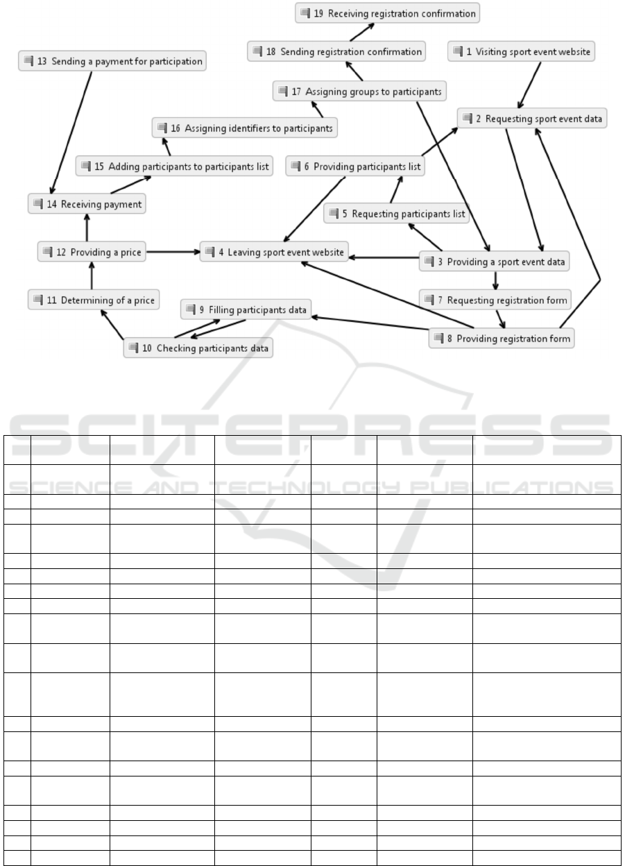
Figure 5: The topological space of “Registration at the sport event” based on transformation of BPMN diagrams.
Table 2: TFM functional features, where V denotes Visitor, SEW – the Sport Event Website, and P - Participant. A set of
post-conditions is empty, and therefore is not presented in the table.
Id Action (A) Result (R) Object (O) Executer
(Ex)
Provider (Pr) Preconditions
1 Visiting sport event
website
V SEW
2 Requesting data [of] sport event V SEW
3 Providing data [of] sport event SEW SEW
4 Leaving sport event
website
V SEW
5 Requesting list [of] participants V SEW
6 Providing list [of] participants SEW SEW
7 Requesting form [of] registration V SEW
8 Providing form [of] registration SEW SEW
9 Filling data [of] participants V SEW (If registration is
available)
10 Checking [validity of data
of]
participants SEW SEW
11 Determining price SEW SEW (All mandatory fields are
filled) AND (Entered data
are correct)
12 Providing price SEW SEW
13 Sending payment [for] participation
[registration]
V External system
14 Receiving payment SEW SEW
15 Adding participants [to] list [of
participants]
SEW SEW (If payment is received)
16 Assigning identifiers [to] participants SEW SEW
17 Assigning groups [to] participants SEW SEW
18 Sending confirmation [of] registration SEW SEW
19 Receiving confirmation [of] registration P External system
MDI4SE 2016 - Special Session on Model-Driven Innovations for Software Engineering
356

Functional features 2, 4, 5, 7, 9, and 13 shows
system’s input signals from Visitor to the website,
while 19 – website’s output signal to Participant.
Next, let us examine functioning cycles. The
TFM has three cycles: checking participant data (9 –
10 - 9), requesting sport event website information
(2 – 3 – 5 – 6 – 2 and 2 – 3 – 7 – 8 - 2), and the main
cycle of the registration process (3 – 7 – 8 – 9 – 10 –
11 – 12 – 14 – 15 – 16 – 17 - 3). The cycles contain
all necessary functional features.
The last is verification of cause and effect
combinations. Verification of single incoming
cause-and-effect relations showed that they all are
necessary and sufficient. Table 3 shows verification
of combinations of incoming combinations of cause-
and-effect relations.
Table 3: Necessity and sufficiency of incoming cause-and-
effect relations in the TFM.
Combination of Cause-and-
Effect Relations
Necess-
ary
Suffi-
cient
XOR {(6-2), (8-2)} True True
XOR {(2-3), (17-3)} True True
XOR {(8-9), (10-9)} True True
XOR {(6-4), (3-4), (8-4), (12-4)} True True
AND {(13-14), (12-14)} True True
Output combinations of cause-and-effect
relations are XOR {(3-5), (3-4)}, XOR {(6-2), (6-
4)}, XOR {(10-11), (10-9)), OR ((17-18), (17-3)},
XOR {(8-2), (8-4), (8-9)}. These also represent
complete sets of effects of functional feature
execution.
Therefore, the constructed BPMN model is
complete (from the functional viewpoint), but
contains one task that is out of system boarders, i.e.
“Visit sport event website”.
5 CONCLUSIONS
The presented approach aims to verification of
completeness of problem domain specification in
BPMN models. It does not solve such problems as
determination of deadlocks, multiple terminations,
transactions, compensations and so on.
The defined mappings between BPMN and TFM
elements allow transformation of a set of BPMN
diagrams to the TFM. Verification of topological
and functioning properties of the TFM helps in
checking completeness of sets of inputs, outputs and
inner functional characteristics as well as
connectedness and causal dependencies of functional
characteristics of the system.
However, to a greater extent the presented
verification approach is manual. Verification of the
logic still requires expert knowledge, and it is a
significant limitation of the approach. The hardest
task is to identify all functioning cycles, since they
are not evident when use output and input events.
However, check of input and output sets of
functional characteristics allows determination of
missed or incorrectly specified triggering conditions.
The future work is dedicated to definition of
patterns for model transformations and a way for
automation of speculations, e.g., using domain
ontologies as a set of valid facts about the domain.
REFERENCES
Asnina, E., 2006. The Computation Independent
Viewpoint: a Formal Method of Topological
Functioning Model Constructing. Applied computer
systems, Volume 26, pp. 21-32.
Asnina, E., 2009. A Formal Holistic Outline for Domain
Modeling. Riga, RTU, pp. 400-407.
Asnina, E. and Osis, J., 2010. Computation Independent
Models: Bridging Problem and Solution Domains. In:
Proceedings of the 2nd InternationalWorkshop on
Model-Driven Architecture and Modeling Theory-
Driven Development (MDA & MTDD 2010), in
conjunction with ENASE 2010. Lisbon: SciTePress,
pp. 23-32.
Asnina, E. and Osis, J., 2011c. Topological Functioning
Model as a CIM-Business Model. In: Model-Driven
Domain Analysis and Software Development:
Architectures and Functions. Hershey - New York:
IGI Global, pp. 40 - 64.
Asnina, E. and Ovčiņņikova, V., 2015. Specification of
Decision-making and Control Flow Branching in
Topological Functioning Models of Systems. In: J.
Filipe and L. Maciaszek, eds. ENASE 2015 :
Proceedings of the 10th International Conference on
Evaluation of Novel Approaches to Software
Engineering, Spain, Barcelona, 29-30 April, 2015.
s.l.:SciTePress, pp. 364-373.
Donins, U., 2012. Topological Unified Modeling
Language: Development and Application, Riga: RTU.
Donins, U. et al., 2011. Towards the Refinement of
Topological Class Diagram as a Platform Independent
Model. In: Proceedings of the 3rd International
Workshop on Model-Driven Architecture and
Modeling-Driven Software Development (MDA &
MDSD 2011). Lisbon: SciTePress, pp. 79-88.
El Hichami, O. et al., 2014. Towards formal verification of
business process using a graphical specification. In:
Information Science and Technology (CIST), 2014
Third IEEE International Colloquium in. s.l.:IEEE,
pp. 12-17.
Falcioni, D., Polini, A., Polzonetti, A. and Re, B., 2012.
Direct Verification of BPMN Processes through an
Verification of BPMN Model Functional Completeness by using the Topological Functioning Model
357

Optimized Unfolding Technique. In: 12th
International Conference on Quality Software (QSIC),
27-29 Aug. 2012. s.l.:IEEE, pp. 179-188.
Flavio, C., Alberto, P., Barbara, R. and Damiano, F., 2010.
An ECLIPSE Plug-In for Formal Verification of
BPMN Processes. In: Communication Theory,
Reliability, and Quality of Service (CTRQ), 2010
Third International Conference on. s.l.:IEEE, pp. 144-
149.
Huai, W., Liu, X. and Sun, H., 2010. Towards
Trustworthy Composite Service Through Business
Process Model Verification. In: Ubiquitous
Intelligence & Computing and 7th International
Conference on Autonomic & Trusted Computing
(UIC/ATC), 2010 7th International Conference on.
s.l.:IEEE, pp. 422-427.
Yamasathien, S. and Vatanawood, W., 2014. An approach
to construct formal model of business process model
from BPMN workflow patterns. In: Digital
Information and Communication Technology and it's
Applications (DICTAP), 2014 Fourth International
Conference on. s.l.:IEEE, pp. 211-215.
Ye, J., Sun, S., Wen, L. and Song, W., 2008.
Transformation of BPMN to YAWL. In: Computer
Science and Software Engineering, 2008 International
Conference on. s.l.:IEEE, pp. 354-359.
Kherbouche, O., Ahmad, A. and Basson, H., 2012.
Detecting structural errors in BPMN process models.
In: Multitopic Conference (INMIC), 2012 15th
International. s.l.:IEEE, pp. 425-431.
Ligeza, A., Kluza, K. and Potempa, T., 2012. AI approach
to formal analysis of BPMN models. Towards a
logical model for BPMN diagrams. In: Computer
Science and Information Systems (FedCSIS), 2012
Federated Conference on. s.l.:IEEE, pp. 931-934.
Morales, L., 2013. Business process verification using a
Formal Compositional Approach and Timed
Automata. In: Computing Conference (CLEI), 2013
XXXIX Latin American. s.l.:IEEE, pp. 1-10.
Object Management Group, 2011. Documents Associated
With Business Process Model And Notation™
(BPMN™) Version 2.0. [Online] Available at:
http://www.omg.org/spec/BPMN/2.0/ [Accessed 10
January 2015].
Object Management Group, 2015. Business Process
Model and Notation. [Online] Available at:
http://www.bpmn.org/ [Accessed 11 January 2015].
Osis, J. and Asnina, E., 2011a. Is Modeling a Treatment
for the Weakness of Software Engineering?. In:
Model-Driven Domain Analysis and Software
Development: Architectures and Functions. Hershey -
New York: IGI Global, pp. 1-14.
Osis, J. and Asnina, E., 2011b. Topological Modeling for
Model-Driven Domain Analysis and Software
Development: Functions and Architectures. In: Model-
Driven Domain Analysis and Software Development:
Architectures and Functions. Hershey - New York:
IGI Global, pp. 15-39.
Osis, J. and Asnina, E., 2011d. Derivation of Use Cases
from the Topological Computation Independent
Business Model. In: Model-Driven Domain Analysis
and Software Development: Architectures and
Functions. Hershey - New York: IGI Global, pp. 65 -
89.
Osis, J. and Asnina, E., 2011. Model-Driven Domain
Analysis and Software Development: Architectures
and Functions. Hershey - New York: IGI Global.
Osis, J., Asnina, E. and Grave, A., 2007. MDA Oriented
Computation Independent Modeling of the Problem
Domain. In: Proceedings of the 2nd International
Conference on Evaluation of Novel Approaches to
Software Engineering (ENASE 2007). Barselona:
INSTICC Press, pp. 66-71.
Osis, J., Asnina, E. and Grave, A., 2008. Computation
Independent Representation of the Problem Domain in
MDA. e-Informatica Software Engineering Journal,
2(1), pp. 29-46.
Osis, J., Asnina, E. and Grave, A., 2008. Formal Problem
Domain Modeling within MDA. In: Software and
Data Technologies, Communications in Computer and
Information Science. Berlin: Springer-Verlag Berlin
Heidelberg, pp. 387-398.
Osis, J. and Donins, U., 2010. Formalization of the UML
Class Diagrams. Berlin, Springer-Verlag, pp. 180-192.
Osis, J. and Slihte, A., 2010. Transforming Textual Use
Cases to a Computation Independent Model. Lisbon,
SciTePress, pp. 33-42.
Slihte, A. and Osis, J., 2014. The Integrated Domain
Modeling: A Case Study. In: Databases and
Information Systems: Proceedings of the 11th
International Baltic Conference (DB&IS 2014),
Estonia, Tallinn, 8-11 June, 2014. Tallinn: Tallinn
University of Technology Press, pp. 465-470.
Slihte, A., Osis, J. and Donins, U., 2011. Knowledge
Integration for Domain Modeling. Lisbon, SciTePress,
pp. 46-56.
Solaiman, E., Sun, W. and Molina-Jimenez, C., 2015. A
Tool for the Automatic Verification of BPMN
Choreographies. New York, NY, IEEE, pp. 728-735.
SPIN, 2015. Verifying Multi-threaded Software with
SPIN. [Online] Available at: http://spinroot.com
/spin/whatispin.html. [Accessed January 2016].
Takemura, T., 2008. Formal Semantics and Verification of
BPMN Transaction and Compensation. In: Asia-
Pacific Services Computing Conference, 2008. APSCC
'08. s.l.:IEEE, pp. 284-290.
Tantitharanukul, N., Sugunnasil, P. and Jumpamule, W.,
2010. Detecting deadlock and multiple termination in
BPMN model using process automata. In: Electrical
Engineering/Electronics Computer
Telecommunications and Information Technology
(ECTI-CON), 2010 International Conference on.
s.l.:IEEE, pp. 478-482.
Universität Hamburg, 2015. Petri Nets World. [Online]
Available at: http://www.informatik.uni-
hamburg.de/TGI/PetriNets/ [Accessed January 2015].
MDI4SE 2016 - Special Session on Model-Driven Innovations for Software Engineering
358
