
Autonomous Mission Management for Forest Search with Multiple
Unmanned Aerial Vehicles
Kemao Peng
1
, Feng Lin
1
and Ben M. Chen
2
1
Temasek Laboratories, National University of Singapore, 117411, Singapore, Singapore
2
Department of Electrical and Computer Engineering, National University of Singapore, 117576, Singapore, Singapore
Keywords:
Unmanned Aerial Systems, Autonomy of UAVs, Multiple UAVs.
Abstract:
An autonomous mission management (AMM) system is designed with the enhanced hierarchical-distributed
methodology (HDM) for multiple unmanned aerial vehicles (UAVs) to search a field of forest together. The
main ideas of the enhanced HDM are hierarchical control and distributed implementation. The event control
law is partitioned into the group and individual event control laws. The group event control law is to coordinate
the group of UAVs to complete the designated mission and the individual event control laws are to complete
the assigned submissions/ tasks accordingly. The group event control law is executed by the leader and any
member can be designated or selected as the leader on the rules. The forest search is applied to verify the
designed AMM system in simulation. The simulation results demonstrate that the designed AMM system is
successful to complete the designated mission by collaborating the group of UAVs.
1 INTRODUCTION
The autonomous mission management (AMM) has
been attracting much attention for the multiple un-
manned aerial vehicles (UAVs) as it is necessary to
coordinate a group of UAVs to complete a designated
mission together (Bellingham et al., 2002), (Inalhan
et al., 2002), (Peng et al., 2014), (Richards et al.,
2002). Such the AMM processes in the high level and
the dynamic processes in the low level of the multi-
ple UAVs construct a typical hybrid system in which
the dynamic processes are time-driven and the AMM
processes are event-driven (Kaminer et al., 2006),
(Tomlin et al., 2000), (Uhrmann and Schulte, 2011),
(van der Schaft and Schumacher, 1998). The event
variables are defined to describe the system behaviors
that are extracted from the time-driven process. The
transition of the discrete event states will become part
of the event control laws to be designed. Thus, too
many defined event variables may result in that the
designed event control laws are not implementable.
Many researchers dedicated their effort to the hy-
brid systems (Jadbabaic et al., 2003), (Kopeikin et al.,
2013), (Lafferriere et al., 2005), (Murata, 1989), (Teo
et al., 2004), (Wong-Toi, 1997), (Ye et al., 1998). The
typical tools such as Petri net and temporal logic are
popularly used in the logic control design of the hy-
brid systems. However, the core problems are still
left to study. One problem is how to describe the sys-
tem behaviors with reasonable number of the event
variables so that the designed event control laws are
implementable. Another problem is the conversion
of the event commands to dynamic commands as the
UAVs are capable only of tracking the dynamic com-
mands. Such conversion is subject to the capabilities
of the UAVs. Otherwise, the event commands are not
executable.
Our objective is to design an AMM system to
collaborate a group of UAVs (quadrotors) to search
a field of forest together. Such system is described
in the hybrid systems. We try to attenuate the ef-
fect of the two problems by reducing number of the
event variables to be defined and defining available
event commands based on the physical process. This
motivated us to propose the enhanced hierarchical -
distributed methodology (HDM).
HDM was proposed for formation flight in (Peng
et al., 2014) . In this paper, it is enhanced for more
complex scenarios so-called the enhanced HDM in
which a submission/ task is decomposed into a series
and/or parallel of tasks/ subtasks respectively as the
UAVs can execute various kinds of tasks/ subtasks si-
multaneously. Such enhancement results in that the
missions can be decomposed perfectly with the se-
ries and/ or parallel relationships in multiple levels.
The main ideas of the enhanced HDM are hierarchi-
Peng, K., Lin, F. and Chen, B.
Autonomous Mission Management for Forest Search with Multiple Unmanned Aerial Vehicles.
DOI: 10.5220/0005949603850392
In Proceedings of the 13th International Conference on Informatics in Control, Automation and Robotics (ICINCO 2016) - Volume 1, pages 385-392
ISBN: 978-989-758-198-4
Copyright
c
2016 by SCITEPRESS – Science and Technology Publications, Lda. All rights reserved
385
❄
A designated mission
Group event
control law
✲
❄
✛
❄
···· · ····
Individual event
control law
event-driven
part
✛
❄
❄
Conversion of
event cmd to
dynamic cmd
Dynamic
control law
✛
✛
✲
❄
✻
Time-driven
part
Control law Plant
UAV 1
Individual event
control law
event-driven
part
✛
❄
❄
Conversion of
event cmd to
dynamic cmd
Dynamic
control law
✛
✛
✲
❄
✻
Time-driven
part
Control law Plant
UAV n
Figure 1: A closed-loop system of multiple UAVs.
cal control and distributed implementation. The event
control law is divided into the group and individual
event control laws. The group event control law is
to focus on the group events to collaborate the group
of UAVs to complete the designated mission together.
The individual event control laws are to focus on the
individual events to complete the assigned submis-
sions/ tasks accordingly. The group event control law
is conducted by the leader. Any group member can be
designated or selected as the leader on the rules.
2 ENHANCED HDM
The enhanced HDM is introduced. The resulting
closed-loop system is shown in Figure 1. A group of
UAVs collaborate to complete a designated mission
together. The event control law consists of the group
and individual event control laws hierarchically. The
group event control law is conducted by any member
when it is designated or selected as the leader. We
mainly consider the group and individual event con-
trol laws, conversion of the event commands to dy-
namic commands and the event-driven transition.
2.1 Group Event Control Design
The group event control law is focused on the group
events such as the mission decomposition, schedule,
assignment and progress. When an accident happens,
the mission reschedule is to be considered.
2.1.1 Mission Decomposition
A mission may be decomposed into a series and/or
parallel of submissions so that it is easy to be com-
pleted by a group of the UAVs together. The mission
is completed when those submissions are completed
accordingly.
m
sn
:= {s
mn,11
,··· , s
mn,ij
,··· ,s
mn,m
s
n
s
}, (1)
where m
sn
denotes the mission decomposition and
s
mn,ij
denotes the i-th and j-th submission. There are
m
s
× n
s
of submissions.
2.1.2 Mission Schedule
A decomposed mission can be scheduled according
to the series and/or parallel relationships between/
among the submissions so that the submissions can
be assigned accordingly.
m
sch
=
s
mn,1
··· s
mn,n
s
,
s
mn,k
=
s
mn,1k
··· s
mn,m
s
k
′
,
k ∈ {1,··· ,n
s
},
(2)
where m
sch
denotes the mission schedule. The sub-
missions are assigned in n
s
of steps and m
s
of the sub-
missions are assigned in the k-th step based on the
event activation conditions.
In the presentation, the row vectors mean series
and the column vectors mean parallel. A series of the
submissions are completed one by one and a parallel
of the submissions in a step are completed in the step.
A zero element of the vectors means no correspond-
ing assignment. No assignment and no activation are
regarded as completed. The rules are applicable to
presentation of the tasks and subtasks hereafter.
2.1.3 Mission Assignment and Progress
The mission assignment and progress can be recorded
in sequence of the mission schedule so that the com-
pleted, being completed and to be completed submis-
sions are presented clearly.
m
ap
=
2 ··· 2 1 0 ··· 0
,
m
sap
=
2 ··· 2 1 0 ··· 0
′
,
(3)
where m
ap
denotes the step progress of the mission
and m
sap
denotes the progress of the submissions in
the being completed step. The element 2 means that
the corresponding step/ submission is completed; 1
means that the corresponding step/ submission is be-
ing completed; 0 means that the corresponding step/
submission is to be completed. The next step/ sub-
missions to be assigned is/are clear based on the event
activation conditions. The meanings of the elements
are applicable to the submission/ task assignment and
progress hereafter.
2.2 Individual Event Control Design
The individual event control laws are focused on the
individual events such as the submission/ task decom-
position, schedule, assignment and progress. when an
ICINCO 2016 - 13th International Conference on Informatics in Control, Automation and Robotics
386

accident happens, the submission/ task reschedule is
to be considered.
2.2.1 Submission/Task Decomposition
A submission/ task may be decomposed into a series
and/or parallel of tasks/ subtasks respectively so that
it is easy to be completed by a UAV. The submis-
sion/ task is completed respectively when the tasks/
subtasks are completed accordingly. The subtasks are
defined as those easily completed by the UAVs.
s
mn
:= {t
sk,11
,··· ,t
sk,ij
,··· ,t
sk,m
t
n
t
},
t
sk
:= {s
tk,11
,··· ,s
tk,ij
,··· ,s
tk,m
st
n
st
},
(4)
where s
mn
denotes the submission decomposition and
t
sk,ij
denotes the i-th and j-th task. There are m
t
× n
t
of tasks. t
sk
denotes the task decomposition and s
tk,ij
denotes the i-th and j-th subtask. There are m
st
× n
st
of subtasks.
2.2.2 Submission/Task Schedule
A decomposed submission/ task can be scheduled ac-
cording to the series and/or parallel relationships be-
tween/ among the tasks/ subtasks so that the tasks/
subtasks can be assigned accordingly.
s
sch
=
t
sk,1
··· t
sk,n
t
,
t
sk,k
=
t
sk,1k
··· t
sk,m
t
k
′
,
k ∈ {1,··· ,n
t
},
t
sch
=
s
tk,1
··· s
tk,n
st
,
s
tk,j
=
s
tk,1j
··· s
tk,m
st
j
′
,
j ∈ {1, · · · ,n
st
},
(5)
where s
sch
denotes the submission schedule. The
tasks are assigned in n
t
of steps and m
t
of the tasks
are assigned in the k-th step based on the event acti-
vation conditions. t
sch
denotes the task schedule. The
subtasks are assigned in n
st
of steps and m
st
of the sub-
tasks are assigned in the j-th step based on the event
activation conditions.
2.2.3 Submission/Task Assignment and Progress
The submission/ task assignment and progress can be
recorded in sequence of the submission/ task sched-
ule so that the completed, being completed and to be
completed tasks/ subtasks are presented clearly.
s
ap
=
2 ··· 2 1 0 ··· 0
,
s
tap
=
2 ··· 2 1 0 ··· 0
′
,
t
ap
=
2 ··· 2 1 0 · · · 0
,
t
sap
=
2 ··· 2 1 0 · · · 0
′
,
(6)
where s
ap
denotes the step progress of the submission
and s
tap
denotes the progress of the tasks in the being
completed step. t
ap
denotes the step progress of the
task and t
tap
denotes the progress of the subtasks in
the being completed step.
2.3 Conversion of Event Commands to
Dynamic Commands
The output of the event control laws is to assign sub-
tasks. Such subtasks, the event commands, need to
be converted properly so that they can be easily con-
ducted by the UAVs. There are three kinds of sub-
tasks such as (1) message subtask: It needs to define
a set of knowledge for the communication between/
among the UAVs. Once a UAV receives a message,
it can understand the message and know how to re-
spond the message; (2) action subtask: It needs to de-
fine a number of actions that the UAVs can easily ex-
ecute. When a UAV is assigned an action subtask, it
can know what kind of action it needs to conduct; and
(3) flight subtask: When a UAV is assigned a flight
subtask, it should know how to complete the flight
subtask. Thus, there needs an online planning to con-
vert the event command, a flight subtask, into the dy-
namic command, the trackable references to the dy-
namic control laws. Based on such conversion, the
event command can be executed by the dynamic con-
trol laws and thus the UAVs can fly on schedule.
2.4 Event-driven Transition
The event state transition is activated by the states of
the defined events. Most of the events are extracted
from the time-driven process to describe the system
behaviors and thus their states depend on the time-
driven process. Therefore, it needs to define the flight
subtask completion conditions so that the states of the
corresponding events can transit correctly.
Based on the flight subtask completion conditions,
the states of the defined events are clear. Therefore,
the activation conditions of the defined events each
can be established according to the event states to
drive the event state transition.
The four parts construct the AMM system in the
high level. This completes introduction of the en-
hanced HDM.
3 DESIGN OF AMM SYSTEM
An AMM system is designed by following the ideas
of the enhanced HDM to collaborate nine UAVs
(quadrotors) to search a field of forest with size of
500 × 500 meters together. The design is subject to
the capabilities of the UAVs and the environment sit-
uation. Next, we proceed to design the AMM system.
Autonomous Mission Management for Forest Search with Multiple Unmanned Aerial Vehicles
387
500 m
500 m
✲
✻
O
Y(E)
X(N)
Accessible side
✻
✲
❄
✻
✲
❄
✻
✲
❄
✻
✲
❄
✻
✲
❄
✻
✲
❄
✲ ✛
L
❄
✻
10 m
✲
✻
O
Y(E)
X(N)
x x x
1 2
3
xxx
12
3
Take-off and landing locations
Figure 2: The forest field.
3.1 Group Event Control Design
The field of forest is assumed to originate normally.
The North-East-Down (NED) frame is defined in Fig-
ure 2. The x denotes the take-off/ landing locations.
The distance between them and the origin is 5 meters.
Only one side of the forest field is accessible.
The field of forest is partitioned into a set of flight
channels in Figure 2 so that the UAVs can search
the forest by flying along the channels. The nomi-
nal distance between the two neighbor channels is set
to L = 40 meters for slight overlap.
The nine UAVs are assigned in three batches and
there are three UAVs in a batch. The first two
batches are pre-scheduled and the third batch is on-
line scheduled based on the search results of the first
two batches. A batch of UAVs are assigned to fly into
the field of forest together. Each UAV is allocated a
round channel to search the forest independently and
records the detected area in 2D map, the detected tar-
gets in the coordinates. All of the members in a batch
meet around the launch site to hand over their data of
the established 2D maps and the found targets to the
batch leader before they land.
The batch leader is designated or selected on the
rules. The batch leader is designated at the beginning
of each batch. The first member in the first batch is
designated as the leader by the ground station. The
first member in the other batches is designated as the
leaders by the leader of the last batch. There is no
batch leader during independentlysearching. The first
UAV that arrives at its meeting point becomes the new
batch leader. A UAV is regarded lost if it cannot arrive
at its meeting point in the given duration. The group
resources are shared by all of members in a batch .
The batch leaders have six duties such as (1) call
all of the members in the batch to take off and to
search independently; (2) collect and merge those 2D
maps and the found targets; (3) schedule the path on-
line based on the merged 2D map and decide number
of UAVs to be assigned in the third batch; (4) hand
over the merged 2D map, found targets, online sched-
uled path, and assignment of the UAVs in the third
batch to the standby UAVs of the next batch; (5) des-
ignate the first member of the next batch as the leader
before it lands; and (6) hand over the merged 2D map
and the found targets to the ground station at end of
the search before it lands.
There is no communication between the UAVs
and the groundstation during the process except at the
beginning and end of the process. At the beginning,
the ground station designates the first member in the
first batch as the batch leader. At the end, the ground
station receives and displays the search results of the
merged 2D map and the found targets. The UAVs can
communicate with each other if they are close. This
is the scenario of the group of UAVs.
3.1.1 Mission Decomposition
Based on the scenario of the group of UAVs, the mis-
sion is decomposed as follows,
m
sn
= {s
mn,11
,··· ,s
mn,ij
,··· , s
mn,33
}, (7)
where s
mn,ij
denotes the submission to be assigned to
the i-th UAV in the j-th batch. Those submissions are
to be defined latter.
3.1.2 Mission Schedule
Based on the mission decomposition, m
sn
, the decom-
posed submissions are scheduled as follows,
m
sch
=
b
atch,1
b
atch,2
b
atch,30
,
b
atch,30
=
b
atch,3
b
atch,
¯
3
′
,
b
atch,
¯
3
= 0, no assignment,
b
atch,k
=
s
mn,1k
s
mn,2k
s
mn,3k
′
,
k ∈ {1,2,3} .
(8)
Based on the mission schedule, m
sch
, nine of the sub-
missions are assigned in three batches and three of
them are assigned together in a batch based on the
event activation conditions.
The mission assignment and progress vectors
record the completed, being completed and to be com-
pleted batch/ submissions. The next batch/ submis-
sions to be assigned is/are clear based on the event
activation conditions. The group event state transition
is shown in Figure 3. The series of the batches are
are completed one by one. The third batch is acti-
vated based on the online decision. A parallel of the
submissions in a batch are completed in the batch ex-
cept that the assigned UAV is lost.
ICINCO 2016 - 13th International Conference on Informatics in Control, Automation and Robotics
388
Start
Batch
1
Batch
2
Batch
3
Stop
✲ ✲ ✲ ✲
✻
Figure 3: Group event state transition.
3.2 Individual Event Control Design
Each UAV is assigned a submission. The submissions
are defined such as (1) receive the related data and
stay on the ground; (2) take off and independently
search the forest along the scheduled channel/path;
(3) broadcast itself flight motion messages; (4) record
the detected areas in 2D map and the found targets
in the coordinates; (5) fly to and hover at the desig-
nated meeting points and attend the selection of the
new batch leader; (6) hand over the recorded data to
the batch leader; and (7) land on the ground and exit.
The submissions of the UAVs in the third batch
are slightly revised only at the flight path that is online
scheduled. The submissions of the UAVs as the batch
leader are also revised. Those UAVs do not need to
hand over the recorded data to the batch leader. But
they have to undertake the duties of the batch leader.
This is the scenario of each UAV.
3.2.1 Submission/ Task Decomposition
Based on the scenario of each UAV, the submissions
are decomposed as follows,
s
mn,ij
= {t
sk,11
,t
sk,21
,t
sk,12
,t
sk,22
,t
sk,32
,t
sk,13
,
t
sk,23
,t
sk,4
,t
sk,15
,t
sk,25
}, i, j ∈ {1,2, 3},
(9)
where the decomposed tasks are listed in Table 1.
Note that s
mn
denotes submission, t
sk
denotes task and
s
tk
denotes subtask.
Table 1: Decomposed tasks.
Task No. Tasks
11 Stay on the geound
21 Rv the related data
12 Take off/ search
22 Tr the motion messages
32 Record the 2D map/targets
13 Hv at the meeting point
23 Hand over the data
4 Landing
15 Landed on the ground
25 Report the landed
Rv receive
Tr transimit
Hv hovering
Table 2: Decomposed subtasks in Task 21.
Subtask No, Subtasks
1 Rv path/Rp
2 Rv agn/Rp
3 Rv 2D map/Rp
4 Rv tgt data/Rp
5 Rv leadership/Rp
6 Tr take-off cmd/Rv Rp
7 Tr group data
8 Rv take-off cmd/Rp
9 Rv group data
Rp respond/resoinse
cmd command
agn assignment
tgt target
The tasks may further be decomposed as follows,
t
sk,21
= {s
tk1,1
,··· ,s
tk1,9
},
t
sk,12
= {s
tk2,1
,··· ,s
tk2,n
st2
},
t
sk,23
= {s
tk3,1
,··· ,s
tk3,17
},
t
sk,4
= {s
tk4,1
,s
tk4,2
},
(10)
where n
st2
= 7 or to be determined online. Task 12
consists of n
st2
line segments at which each segment is
as a flight subtask.Task 4 consists of 2 line segments.
Task 21 and Task 23 consist of the message subtasks
which are listed in Table 2 and 3 respectively. The
other tasks are as simple as the subtasks and thus no
decomposition is needed.
3.2.2 Submission/ Task Schedule
Based on the submission decomposition, s
mn,ij
, the
decomposed tasks are scheduled as follows,
s
sch,ij
=
t
sk,1
t
sk,2
t
sk,3
t
sk,4
t
sk,5
,
t
sk,1
=
t
sk,11
t
sk,21
′
, i, j ∈ {1,2,3},
t
sk,2
=
t
sk,12
t
sk,22
t
sk,23
′
,
t
sk,3
=
t
sk,13
t
sk,23
′
,
t
sk,5
=
t
sk,15
t
sk,25
′
,
(11)
Based on the task decomposition, t
sk,ij
, the decom-
posed tasks are scheduled as follows,
t
sch,21
=
s
tk1,10
s
tk1,50
,
s
tk1,10
=
s
tk1,11
s
tk1,21
s
tk1,31
′
,
s
tk1,11
= 0, no assignment,
s
tk1,21
=
s
tk1,3
s
tk1,4
,
s
tk1,31
=
s
tk1,1
s
tk1,2
s
tk1,3
s
tk1,4
,
(12)
s
tk1,50
=
s
tk1,15
s
tk1,25
′
,
s
tk1,15
=
s
tk1,5
s
tk1,6
s
tk1,7
,
s
tk1,25
=
s
tk1,8
s
tk1,9
,
Autonomous Mission Management for Forest Search with Multiple Unmanned Aerial Vehicles
389
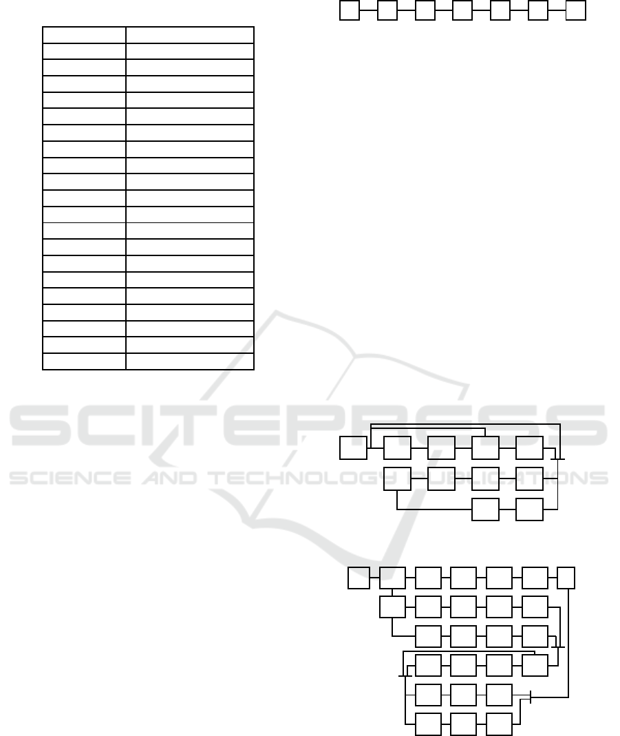
Table 3: Decomposed subtasks in Task 23.
Subtask No. Subtasks
1 Iq leadership
2 No Rp to Iq
3 Rp Iq/Rv Rp
4 Rq 2D map/Rv
5 Rq tgt data/Rv
6 Tr lnd cmd/ Rv Rp
7 Merge map/tgt data
8 Online scheduling
9 Tr path/Rv Rp
10 Tr agn/Rv Rp
11 Tr 2D map/Rv Rp
12 Tr tgt data/Rv Rp
13 Tr leadership/Rv Rp
14 Rv Rp to Iq/Rp
15 Rv Rq/Tr 2D map
16 Rv Rq/Tr tgt data
17 Rv lnd cmd/Rp
lnd landing
Iq inquire/inquiry
Rq request
t
sch,12
=
s
tk2,1
··· s
tk2,n
st2
,
t
sch,4
=
s
tk4,1
s
tk4,2
,
(13)
t
sch,23
=
s
tk3,1
s
tk3,20
,
s
tk3,20
=
s
tk3,120
s
tk3,220
′
,
s
tk3,120
=
s
tk3,14
s
tk3,15
s
tk3,16
s
tk3,17
,
s
tk3,220
=
s
tk3,2
s
tk3,30
s
tk3,7
s
tk3,80
s
tk3,110
,
s
tk3,30
=
s
tk3,130
s
tk3,230
′
,
s
tk3,80
=
s
tk3,18
s
tk3,28
′
,
s
tk3,110
=
s
tk3,111
s
tk3,211
′
,
s
tk3,18
= 0, no assignment,
s
tk3,28
=
s
tk3,8
s
tk3,9
s
tk3,10
,
s
tk3,k30
=
s
tk3,3
s
tk3,4
s
tk3,5
s
tk3,6
,
s
tk3,k11
=
s
tk3,11
s
tk3,12
s
tk3,13
,
k ∈ {1,2}.
(14)
Based on the submission/ task schedules, the decom-
posed tasks/ subtasks can be assigned accordingly.
The submission/ task assignment and progress vectors
record the completed, being completed and to be com-
pleted step/ task/ subtask. The next step/ task/ subtask
is clear based on the event activation conditions.
The submission event state transition is shown in
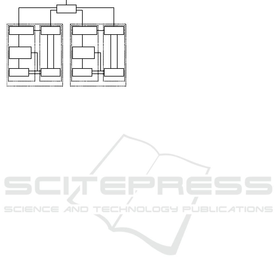
Figure 4. The event state transition in Task 21 is
shown in Figure 5. There are three branches from the
enter for the three batches respectively. The UAVs in
the first batch do not need to receive the online sched-
uled path and assignment, the merged 2D map and
targets. The UAVs in the second batch do not need
Enter
T
ask
1
T
ask
2
T
ask
3
T
ask
4
T
ask
5
End
✲ ✲ ✲ ✲ ✲ ✲
Figure 4: Submission event state transition.
to receive the online scheduled path and assignment,
but they need to receive the merged 2D map and tar-
gets. The UAVs in the third batch if applicable need
to receive the online scheduled path and assignment,
as well as the merged 2D map and targets. The subse-
quent two branches are for the batch leader and mem-
bers respectively.
The event state transition in Task 23 is shown in
Figure 6. The UAVs in a batch attend the leader selec-
tion for the new batch leader. There are two branches
of the outcome. One is for the members and the other
is for the new batch leader. The leader needs to col-
lect the data from the two members respectively in
two branches. After merging the 2D map and found
targets, the leader conducts the online schedule only
in the second batch. Thus, one branch is no assign-
ment and the other is for the online schedule. Sub-
sequently, the leader needs to hand over the merged
map and found targets to the standby UAVs in the next
batch in one branch and in the other branch hand over
them to the ground station at end of the search. This
completes the individual event control design.
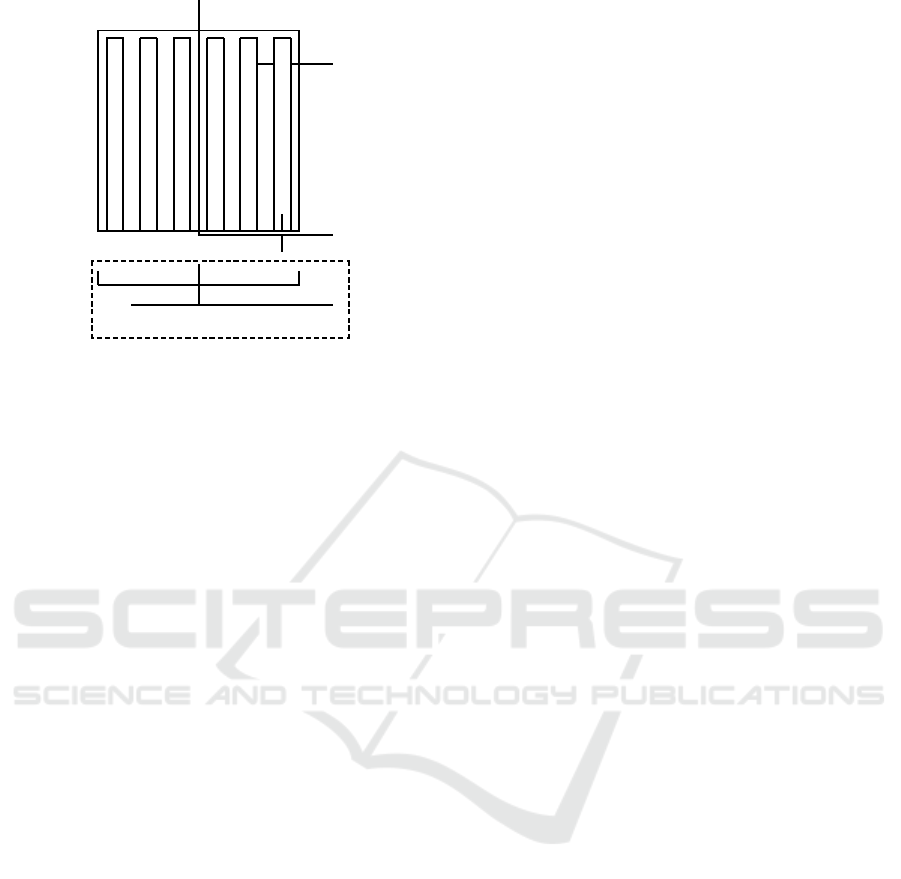
Enter
S
ubtask
1, 1
S
ubtask
1, 2
S
ubtask
1, 3
S
ubtask
1, 4
✲ ✲ ✲ ✲
❄
❄❄
S
ubtask
1, 5
S
ubtask
1, 6
S
ubtask
1, 7
S
ubtask
1, 8
S
ubtask
1, 9
End
✛✛✛✛
✛✛
✻
Figure 5: The event state transition in Task 21.
Enter
S
ubtask
3, 1
S
ubtask
3, 14
S
ubtask
3, 15
S
ubtask
3, 16
S
ubtask
3, 17
End
✲ ✲ ✲ ✲ ✲ ✲
S
ubtask
3, 2
S
ubtask
3, 3
S
ubtask
3, 4
S
ubtask
3, 5
S
ubtask
3, 6
❄
✲ ✲ ✲ ✲
S
ubtask
3, 3
S
ubtask
3, 4
S
ubtask
3, 5
S
ubtask
3, 6
✲ ✲ ✲ ✲
S
ubtask
3, 7
S
ubtask
3, 8
S
ubtask
3, 9
S
ubtask
3, 10
❄❄
✛✛✛✛
❄❄
S
ubtask
3, 11
S
ubtask
3, 12
S
ubtask
3, 13
✲ ✲ ✲ ✲
S
ubtask
3, 11
S
ubtask
3, 12
S
ubtask
3, 13
✲ ✲ ✲
✲
✻
Figure 6: The event state transition in Task 23.
3.3 Conversion of Event Commands to
Dynamic Commands
Eighteen sets of the knowledge are defined for the
message subtasks and two sets of the action are de-
ICINCO 2016 - 13th International Conference on Informatics in Control, Automation and Robotics
390
fined for the action subtasks. The flight subtasks are
presented as the line segnebts in the starting and end
points and thus they need to be converted into the
trackable references of the position, velocity and ac-
celeration by the UAVs.
There may be four phases to complete the flight
subtasks such as the acceleration (Ac), velocity hold-
ing (Hd), deceleration (Dc) and hovering (Hv). The
first three phases are velocity tracking and the last
phase is position tracking.
Hv, d ≤ d
hv
Ac+ Hv, d
hv
< d ≤ 2d
hv
,
Ac+ Dc+ Hv, 2d
hv
< d ≤ d
hd
,
Ac+ Hd+ Dc+ Hv, d > d
hd
,
(15)
where d
hv
denotes the distance that the UAVs can
hover from one point to another point. d
hd
denotes
the distance that the UAVs need to hold the maximal
speed to fly. d
hd
= v
2
max
/a
max
with v
max
and a
max
be-
ing the maximal speed and acceleration. d denotes the
distance between the starting point, p
s
, and end point,
p
e
. d = kp
e
− p
s
k. The trackable references can be
computed well for the four phases each. The heading
reference is the direction of the flight subtask from the
starting point to the end point in the first three phases
and it is the direction of the next flight subtask in the
last phase or pointing to the North if the next flight
subtask is hovering. With such conversions, the event
commands are executable.
3.4 Event-driven Transition
A set of the event activation conditions are defined
to control the transition of the discrete event states.
The flight subtask completion conditions are defined
based on the distance along the direction of the flight
subtask. The flight subtask is completed when
d
f
≤ 0, d
f
= (p
e
− p)
′
(p
e
− p
s
)/d,
where p denotes the position of the UAV. d
f
denotes
the projection of the distance to be flied relative to the
end point to the direction of th flight subtask. If the
flight subtask is hovering, it is completed when the
hovering is over the given duration. With the flight
subtask completion conditions, the transition of the
discrete event states is clear.
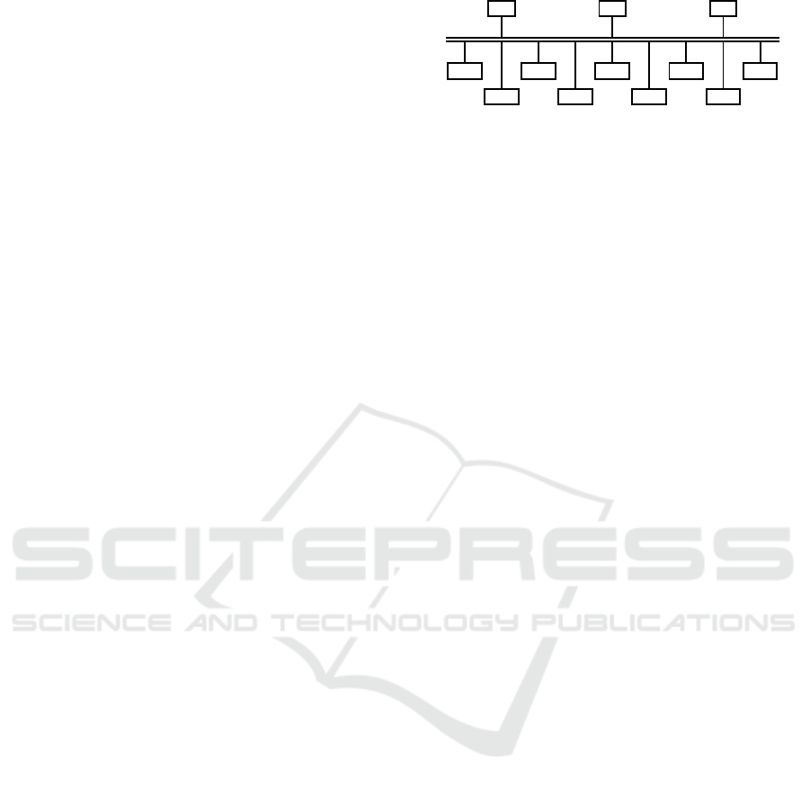
4 SIMULATION
The simulation is conducted to verify the designed
AMM system to coordinate nine of the UAVs to
search the field of forest. The resulting closed-loop
system is shown in Figure 7 in which Gds denotes
Gds Cmm Env
UAV 1 UAV 2 UAV 3 UAV 4 UAV 5
UAV 6 UAV 7 UAV 8 UAV 9
Figure 7: A simulation system of multiple UAVs.
the ground station, Cmm denotes the communication
system and Env denotes the surroundingenvironment.
In the simulation,, one UAV is assumed lost in
the first batch and another UAV is lost in the second
batch. Based on the merged map, the online schedule
decides to assign two UAVs and schedules the path
for them each to search the missed areas in the third
batch. Then, the full of the forest field is searched.
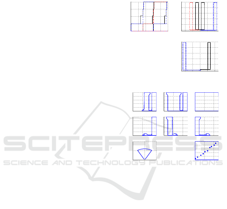
The discrete event states and flight trajectories of
the UAVs are shown in Figure 8. The 2D maps built
and merged by the UAVs to describe the detected ar-
eas are shown in Figure 9. The simulation results
demonstrate that the designed AMM system is suc-
cessful to coordinate the group of UAVs to search the
field of forest together. The number of the defined
events is not too many to affect the implementation of
the AMM system. The designed AMM system is also
successfully verified in our high-fidelity simulator.
5 CONCLUDING REMARKS
The enhanced HDM has been successfully applied to
design an AMM system to collaborate multiple UAVs
to complete a designated mission together. The main
features of the designed AMM system are hierarchi-
cal control, series and/or parallel decomposition and
distributed implementation. The missions can be de-
composed perfectly with the series and/or parallel re-
lationships in multiple levels. The enhanced HDM
is applicable to the other more complex scenarios.
Nonetheless, the mission reschedule is to be studied
when an accident happens.
REFERENCES
Bellingham, J., Tillerson, M., Alighanbari, M., and How, J.
(2002). Cooperative path planning for multiple uavs in
dynamic and uncertain environments. In Proceedings
of the 41st IEEE Conference on Decision and Control,
pages 2816–2822, Las Vegas, Nevada, USA. IEEE.
Inalhan, G., Stipanovic, D., and Tomlin, C. (2002). De-
centralized optimization with application to multi-
ple aircraft coordination. In Proceedings of the 41st
IEEE InternationalConference on Decision and Con-
Autonomous Mission Management for Forest Search with Multiple Unmanned Aerial Vehicles
391
trol, pages 1147–1155, Las Vegas, Venada, USA.
IEEE.
Jadbabaic, A., Lin, J., and Morse, A. S. (2003). Coordi-
nation of groups of mobile autonomous agents with
neighbor rules. IEEE Transactions on Automatic Con-
trol, 48(6):998–1001.
Kaminer, I., Yakimenko, O., Pascoal, A., and Ghabcheloo,
R. (2006). Path generation, path following and co-
ordinated control for timecritical missions of multiple
uavs. In Proceedings of 2006 American Control Con-
ference, Minneapolis, MN, USA. IEEE.
Kopeikin, A. N., Ponda, S. S., Johnson, L. B., and How,
J. P. (2013). Dynamic mission planning for commu-
nication control in multiple unmanned aircraft teams.
Unmanned Systems, 1(1):41–58.
Lafferriere, G., Williams, A., Caughman, J., and Veerman,
J. E. (2005). Decentralized control of vehicle forma-
tions. Systems and Control Letters, 54(9):899–910.
Murata, T. (1989). Petri nets: properties, analysis and ap-
plications. Proceedings of the IEEE, 77(4):541–580.
Peng, K., Pang, T., Lin, F., and Chen, B. M. (2014). Au-
tonomous mission execution for multiple unmanned
aerial vehicles with hierarchical-distributed method-
ology. In Proceedings of 2014 11th IEEE Interna-
tionalConference on Control and Automation, pages
1369–1374, Taichung, Taiwan. IEEE.
Richards, A., abd M. Tillerson, J. B., and How, J. (2002).
Coordination and control of multuple uavs. Aiaapaper
2002–4588.
Teo, R., Jang, J. S., and Tomlin, C. J. (2004). Automated
multiple uav flight the stanford dragonfly uav pro-
gram. In Proceedings of the 43rd IEEE Internation-
alConference on Decision and Control, pages 4268–
4273, Atlantis, Geogia, USA. IEEE.
Tomlin, C. J., Lygeros, J., and Sastry, S. S. (2000). A game
theoretic approach to controller design for hybrid sys-
tems. Proceedings of the IEEE, 88(7):949–969.
Uhrmann, J. and Schulte, A. (2011). Task-based guid-
ance of multiple uav using cognitive automation.
In Proceedings of 2011 International Conference on
Advanced Cognitive Technologies and Applications,
Rome, Utaly. ABIA.
van der Schaft, A. J. and Schumacher, H. (1998). Comple-
mentarity modeling of hybrid systems. IEEE Trans-
actions on Automatic Control, 43(4):483–490.
Wong-Toi, H. (1997). The synthesis of controllers for lin-
ear hybrid automata. In Proceedings of the 1997 IEEE
Conference on Decision and Control, pages 4607–
4613, San Diego, CA, USA. IEEE.
Ye, H., Michel, A., and Hou, L. (1998). Stability theory
for hybrid dynamical systems. IEEE Transactions on
Automatic Control, 43(4):461–474.
APPENDIX
−200 −100 0 100 200
0
100
200
300
400
500
p
x
(m, North)
p
y
(m, East)
0 500 1000 1500 2000 2500
1
2
3
4
5
Event states
Time (s)
−200 −100 0 100 200
0
100
200
300
400
500
p
x
(m, North)
p
y
(m, East)
Batch 1
Batch 2
Batch 3
Batch 3
Number of the defuned event states is 102.
13 of the event states are used for each UAV.
2 of the event states are for the ground station.
One UAV is lost in Batch 1.
Another UAV is lost in Batch2.
Batch 3 is scheduled online based on
the search results of the first two batches.
Batch 2 Batch 1
Figure 8: Event states and flight trajectories of UAVs.
200 250 300
0
50
100
p
y
(m, East)
p
x
(m, North)
0 200 400
0
100
200
300
400
500
p
x
(m, North)
0 200 400
0
100
200
300
400
500
p
x
(m, North)
0 200 400
0
100
200
300
400
500
0 200 400
0
100
200
300
400
500
p
y
(m, East)
0 200 400
0
100
200
300
400
500
0 200 400
0
100
200
300
400
500
0 200 400
0
100
200
300
400
500
p
y
(m, East)
p
x
(m, North)
UAV(1,1)
UAV(2,1)
UAV(1,2)
UAV(3,2)
UAV(1,3)
UAV(2,3)
Gds
Sensor detected area
1
0
0
1
1
1
1
0
0
0
1: detected
1
1
0: undetected
1
0
1
0
1
1
1st row: merged maps.
2nd row: maps of single UAV.
1st batch:UAV(1,1) and (2,1).
2nd batch: UAV(1,2) and (3,2).
3rd batch: UAV (1,3) and (2,3).
Gds: ground station.
10 targets are detected.
Targets
Figure 9: Maps of the detected areas by UAVs.
ICINCO 2016 - 13th International Conference on Informatics in Control, Automation and Robotics
392
