
The Real-time Tracking Servo Control of a Rodless Pneumatic
Actuator System under an Asymmetrical Load via the Feedback
Measurement System
Hao-Ting Lin
Department of Mechanical and Computer-Aided Engineering, Feng Chia University,
No. 100, Wenhwa Road, Seatwen, Taichung 40724, Taiwan, ROC
Keywords: Rodless Pneumatic Cylinder, Asymmetrical Load, Feedback Measurement System, Real-time Control, Path
Tracking Servo Control.
Abstract: Due to the nonlinear and time-varying characteristics, pneumatic servo control systems are difficult to
realize real-time path tracking control, especially for the rodless pneumatic cylinder which has relative
larger friction force. An asymmetrical vertical load resulting from the gravity makes the motion control in
the vertical direction more difficult. This study develops a rodless pneumatic actuator system for the real-
time tracking servo control with an asymmetrical vertical load. First, the dynamic models of the rodless
pneumatic actuator system will be established and simulated by the Matlab software. Then, the test rig
layout will be proposed and experimented under the asymmetrical load via the feedback measurement
system. Finally, the experimental results show that a rodless pneumatic actuator system with the
asymmetrical vertical load is successfully implemented for the path tracking profile.
1 INTRODUCTION
The pneumatic system is one of the power sources to
perform in the industry. Due to its reliability, low
cost, cleanness, simplicity, easy maintenance, and
safety in operation, the pneumatic system has
gradually been widely adopted in the industrial
automation. In recent years, pneumatic actuators
have been used to work on positioning and motion
tasks, and quite suitable for applying in the robotics
fields. However, compared with electrical motors
with equal power, pneumatic actuators are still not
competitive in a few applications which demand
accuracy, versatility and flexibility. Although
pneumatic actuators have disadvantages such as high
nonlinearity, low natural frequency due to low
stiffness of air compressibility, and control
complexity, researches on robots with the pneumatic
actuator system are still popular in the automation
industry.
Because pneumatic system is a highly nonlinear
system and does not easily get accurate
mathematical models, it is difficult and complicated
to accomplish the pneumatic servo control (Oyama
et al, 1990). To resolve the above problems, some
researcher adopted the model reference control
scheme (Gyeviki et al, 2005). In additional, Chiang
and Lin proposed a Fourier series-based adaptive
sliding-mode controller with H-inf tracking
performance for the rodless pneumatic cylinder
system (Chiang and Lin, 2011). The proposed
method can not only be effective in preventing
approximation errors, disturbance, and un-modeled
dynamics, but it also guarantees a desired H-inf
tracking performance for the overall system.
In this paper, the rodless pneumatic actuator is
set up in the vertical direction to be an asymmetrical
load mechanism system. For this system, the
properties of mass, flow and pressure between two
chambers of the pneumatic actuator are totally
different while the pneumatic actuator works. These
properties affect the overall system dramatically and
the real-time control for the path tracking servo
control is more difficult. In this research, the Matlab
simulation will be establish to simulate the proposed
system via the mathematical models and control
methods. Finally, the test results indicate that the
rodless pneumatic actuator system with an
asymmetrical vertical load can follow the desired
path profiles and achieve the required accuracy.
Lin, H-T.
The Real-time Tracking Servo Control of a Rodless Pneumatic Actuator System under an Asymmetrical Load via the Feedback Measurement System.
DOI: 10.5220/0005950603990403
In Proceedings of the 13th International Conference on Informatics in Control, Automation and Robotics (ICINCO 2016) - Volume 1, pages 399-403
ISBN: 978-989-758-198-4
Copyright
c
2016 by SCITEPRESS – Science and Technology Publications, Lda. All rights reserved
399
2 DESCRIPTION OF THE
SYSTEM
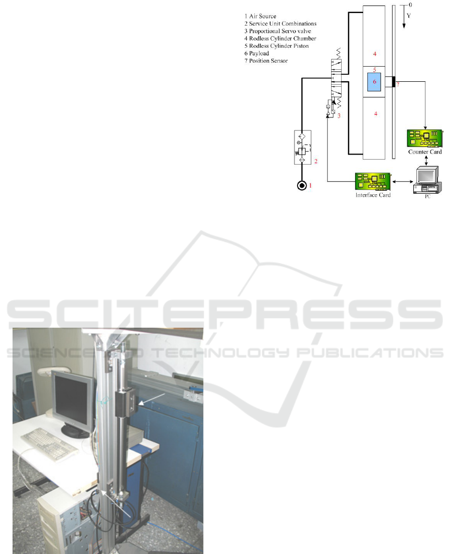
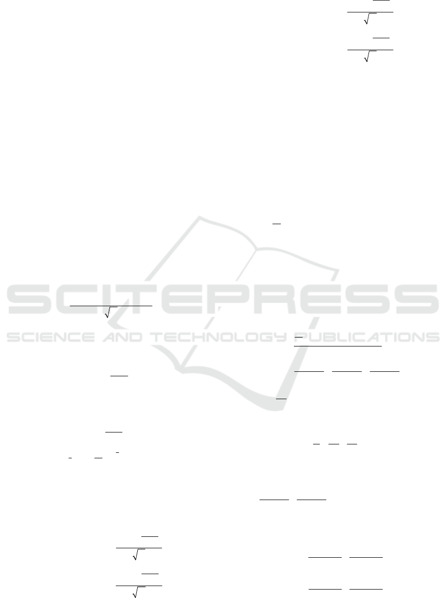
Figure 1 photographically shows the test rig of the
rodless pneumatic servo system with an
asymmetrical vertical load. The test rig layout is
shown in Figure 2. In Figure 2, the real-time control
of the rodless pneumatic actuator system mainly has
five parts which are an air source unit, a rod-less
pneumatic actuator, a proportional servo valve,
signal processing cards and a PC-based controller
unit. The air pressure for the experiments is set as
0.5 MPa. The rod-less pneumatic actuator and the
proportional servo valve are manufactured by
FESTO. The type of the rod-less pneumatic actuator
is DGC-25-500-KF-YSR-A and the model of the
pneumatic proportional servo valve is MPYE-5-M5-
010-B. An optical linear encoder has a resolution of
0.1 μm for the feedback measurement system. The
PC-based controller is a feedback measurement
control unit which handles the control signals for the
pneumatic proportional servo valve by an AD/DA
interface card and gathers the feedback measuring
signals for itself via a counter card. The control
software of the overall system is computed by a 32-
bit Open Watcom C program and the sampling
frequency is 1000 Hz.
Figure 1: Rodless pneumatic actuator system.
Figure 2: Test rig layout.
3 DYNAMIC MODELS AND THE
CONTROL STRATEGY OF A
RODLESS PNEUMATIC
ACTUATOR SYSTEM WITH AN
ASYMMETRICAL VERTICAL
LOAD
In this research, the rodless pneumatic actuator is
arranged in the vertical direction for the path
tracking servo control. In this case, the gravity effect
plays an important role in the rodless pneumatic
actuator system with a vertical load. Therefore, the
proposed system is an asymmetrical system when
the block shifts dynamically in the rodless
pneumatic actuator. The block motion in the
pneumatic cylinder can dramatically influence the
air flow rates and pressure changes between two
cylinder chambers. In this chapter, the nonlinear
mathematical models of the asymmetrical rodless
pneumatic actuator system is derived inclusive of the
dynamics of pneumatic servo valve, the mass flow
rate equation of the pneumatic cylinder, the
continuity equation and the motion equation. To
implement the real-time servo control of a rodless
pneumatic actuator system under an asymmetrical
load, a Fourier series-based adaptive sliding mode
controller with H-inf tracking performance
(FSBASMC+Hinf) [3] is used for the overall
feedback measurement system in this study.
ICINCO 2016 - 13th International Conference on Informatics in Control, Automation and Robotics
400
3.1 The Dynamics of the Pneumatic
Servo Valve
A proportional directional flow control valve is used
in this experiment. The main feature of this type of
valve is that its input control signal and the valve
spool position is in the linear relationship. Hence,
the dynamics of the valve can be described by the
following relation:
() ( () ())
vn
Xt K ut u t=−
(1)
where
()
X
t
is the valve spool displacement of the
pneumatic servo valve,
v
K
represents the
displacement-voltage gain,
)(tu
is the control input
and
()
n
ut
is the neutral voltage.
3.2 The Mass Flow Rate Equation of
the Pneumatic Cylinder
The mass flow rate of the air is dependent on the
orifice area, temperature and pressure difference
across the orifice, when the air flows through an
orifice. In Figure 2, considering the mass flow rate
of pneumatic cylinder chambers A and B, the
following equation can be expressed as
0
() () ( ())
()
dur
u
CCwX tP t f p t
mt
T
=
(2)
where
d
C
is the discharge coefficient (
0.8
d
C =
),
0
C
is
the mass flow parameter,
w
is the port width (m),
()
u
P
t
is the up-stream pressure (N/m
2
),
u
T
is the up-
stream temperature,
()
()
()
d
r
u
P
t
pt
P
t
=
is the ratio between
the down-stream and up-stream pressure,
)(tP
d
is the
down-stream pressure (N/m
2
), and
1
21
2
1, ( )
()
(())
() () , () 1
atm
rr
u
r
k
kk
kr r r r
P
pt C
Pt
fpt
Cpt p t C pt
+
⎧
<<
⎪
⎪
=
⎨
⎡⎤
⎪
−<<
⎢⎥
⎪
⎣⎦
⎩
(3)
For air,
k
=1.4 is the specific heat constant,
r
C
=0.528 and
k
C
=3.864. In order to simplify the
analysis, the following functions can be derived as
()
() ( )
()
ˆ
( ( ), ( ), ( ))
()
() ( )
()
a
s
s
s
ase
e
a
a
a
P
t
Ptf
P
t
T
fPt Pt Pt
P
t
Ptf
P
t
T
⎧
⎪
⎪
⎪
⎪
=
⎨
⎪
⎪
⎪
⎪
⎩
(4)
()
() ( )
()
ˆ
( ( ), ( ), ( ))
()
() ( )
()
e
b
b
b
bse
b
s
s
s
P
t
Ptf
P
t
T
fPtPtPt
P
t
Ptf
P
t
T
⎧
⎪
⎪
⎪
⎪
=
⎨
⎪
⎪
⎪
⎪
⎩
(5)
where
s
P
=5×10
5
(N/m
2
) is the supply pressure,
e
P
=1
×10
5
(N/m
2
) is the exhaust pressure,
a
P
and
b
P
are
the pressure values of the chamber A and B,
s
T
=293K is the supply temperature,
a
T
and
b
T
are
the temperature values in the chamber A and B.
3.3 The Continuity Equation
We assume that the air into the cylinder is an
adiabatic process of an ideal gas, the change in
energy can be shown as
( () ) () () ()
vc s Ps
d
cVtT mtCTPtVt
dt
ρ
=−
(6)
where
v
c
is the specific heat of air at constant
volume,
c
ρ
is the air density of the cylinder,
()Vt
is
the volume of the cylinder,
()mt
is the mass flow
rate,
P
C
is the specific heat of air at a constant
pressure and
()Pt
is the pressure of the chamber.
Assuming an ideal gas
( () ) () ()
()
() () () () () ()
vc s
Ps
ssPs
d
cVtT PtVt
dt
mt
CT
P
tV t PtV t PtV t
kRT kRT C T
ρ
+
=
=++
(7)
where
P
v
C
k
c
=
is the ratio of the specific heat for air
at the temperature
s
T
. For an ideal gas
111
P
R
CkR
=+
(8)
where R=287 (J/kg*K) is the universal gas constant.
Then
() () () ()
()
ss
P
tV t PtV t
mt
kRT RT
=+
(9)
For the chamber A and B, the following equations
hold:
() () () ()
()
aa aa
a
ss
P
tV t P tV t
mt
kRT RT
=+
(10)
() () () ()
()
bb bb
b
ss
P
tV t P tV t
mt
kRT RT
=+
(11)
The Real-time Tracking Servo Control of a Rodless Pneumatic Actuator System under an Asymmetrical Load via the Feedback
Measurement System
401
where V
a
and V
b
are the volumes of the chamber A
and B. Combining Eqs. (2)-(5), (10) and (11) as
0
ˆ
() ( (), (), ()) () ()
()
()
sd a s e a a
a
a
kRTCCwXtfPtPtPt kPtVt
Pt
Vt
−
=
(12)
0
ˆ
() ( (), (), ()) () ()
()
()
sd b s e b b
b
b
kRTCCwXtfPtPtPt kPtVt
Pt
Vt
−
=
(13)
3.4 The Motion Equation
Applying the Newton’s second law of motion, the
asymmetric pneumatic cylinder’s motion can be
described as
(() ())sgn(()) ()
( ( )) ( ( ), ( ), ( )) ( )
ab f
Sc a b
AP t AP t x t K x t
KxtSxtPtPt MgMxt
−
−−
−−=
(14)
where
A
denotes the piston area (m
2
),
M
is the mass
(kg), Mg indicates the asymmetrical vertical
payload,
f
K
is the viscous friction coefficient, and
()
Sc
Kx
−
is the combination of static and Coulomb
friction forces which are position and velocity
dependent. Function is expressed as
( ( )) ( ( ), ( ), ( ))
Sc a b
KxtSxtPtPt
−
() (),
0()()(())
( ( )) ( ( ), ( ), ( ))
( ( ))sgn( ( )),
0()()(())
ab
abS
Sc a b
c
abS
AP t AP t
as x and AP t AP t K x t
KxtSxtPtPt
Kxt xt
as x or AP t AP t K x t
−
−
⎧
⎪
=−≤
⎪
=
⎨
⎪
⎪
≠−>
⎩
(15)
where
(())
S
Kxt
is the position-dependent static
frictions,
(())
c
Kxt
is the variable position-dependent
load via friction effects.
Furthermore,
()
a
Vt
and
()
b
Vt
are defined as
() ( () )
a
Vt Axt=+Δ
(16)
() ( () )
b
Vt Al xt=−+Δ
(17)
where
l
is the stroke (m),
Δ
is an equivalent extra
length to the cylinder.
3.5 Control Strategy
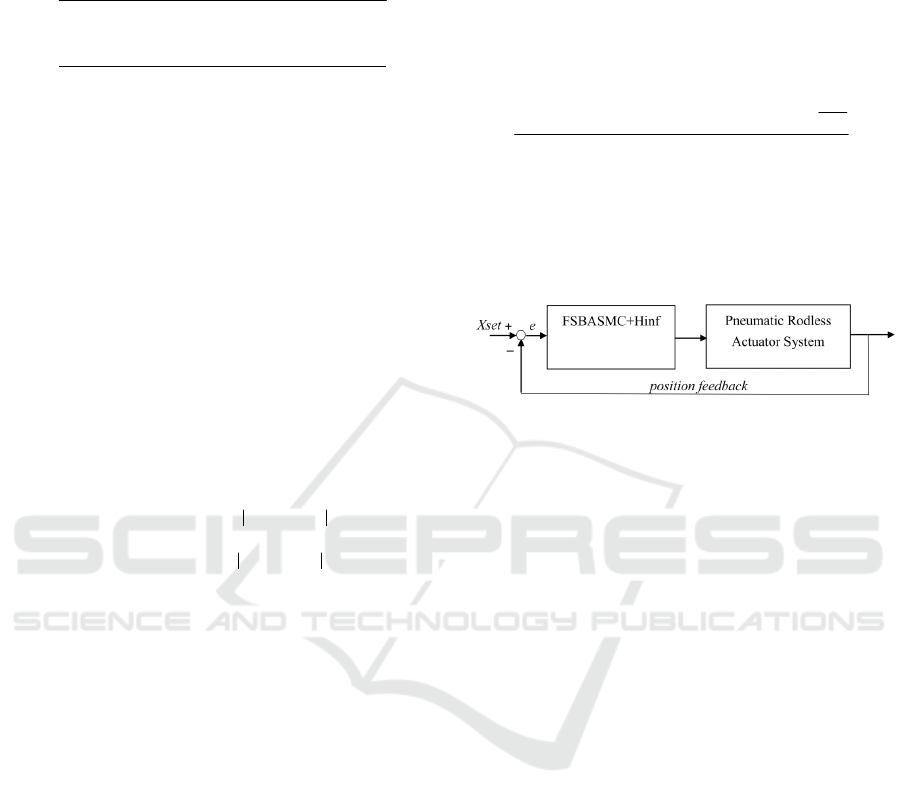
The block diagram of the overall scheme is shown in
Figure 3. To realize the real-time path tracking servo
control for the rodless pneumatic actuator system
under an asymmetrical load, the FSBASMC-Hinf is
adopted in this study. Define the output error as
)()()( tytyte
m
−=
(18)
where
)(ty
m
is a given bounded reference signal. The
sliding surface is described as
)(...)()(
)1(
21
teteateas
n−
+++=
(19)
where
i
a
are chosen such that
∑
=
−
n
i
i
i
a
1
1
λ
is a Hurwitz
polynomial. In this paper, the FSBASMC-Hinf
controller is proposed to solve the high non-linearity
and time-varying problems of the rodless
pneumatics servo system under the asymmetrical
load. Therefore, the control input is chosen as
3
1 2 21 22
2
ˆ
() ()
2
ˆ
()
T
FF m
T
GG
s
t aeaepe peyt
u
t
ρ
−−−−−+−
=
Wq
Wq
iii i
(20)
where the sliding surface defined as
540
s
ee e=+ +
,
initial values of Fourier coefficients
ˆ
F
W
and
ˆ
g
W
are
111
[0,0, , 0]
×
and
111
[20000,0, ,0]
×
, respectively,
1
a
is
40,
2
a
is 5 and
ρ
=
0.2.
Figure 3: The block diagram of the overall scheme.
4 SIMULATIONS AND
EXPERIMENTS
First, the simulation of the overall rodless pneumatic
actuator system is established by the Matlab
software. Next the experiments of path tracking
servo control in a rodless pneumatic system under an
asymmetrical load are implemented. In the
experiments, the desired path trajectory, namely a
fifth-order polynomial function is chosen for the
real-time path tracking servo control in the vertical
direction.
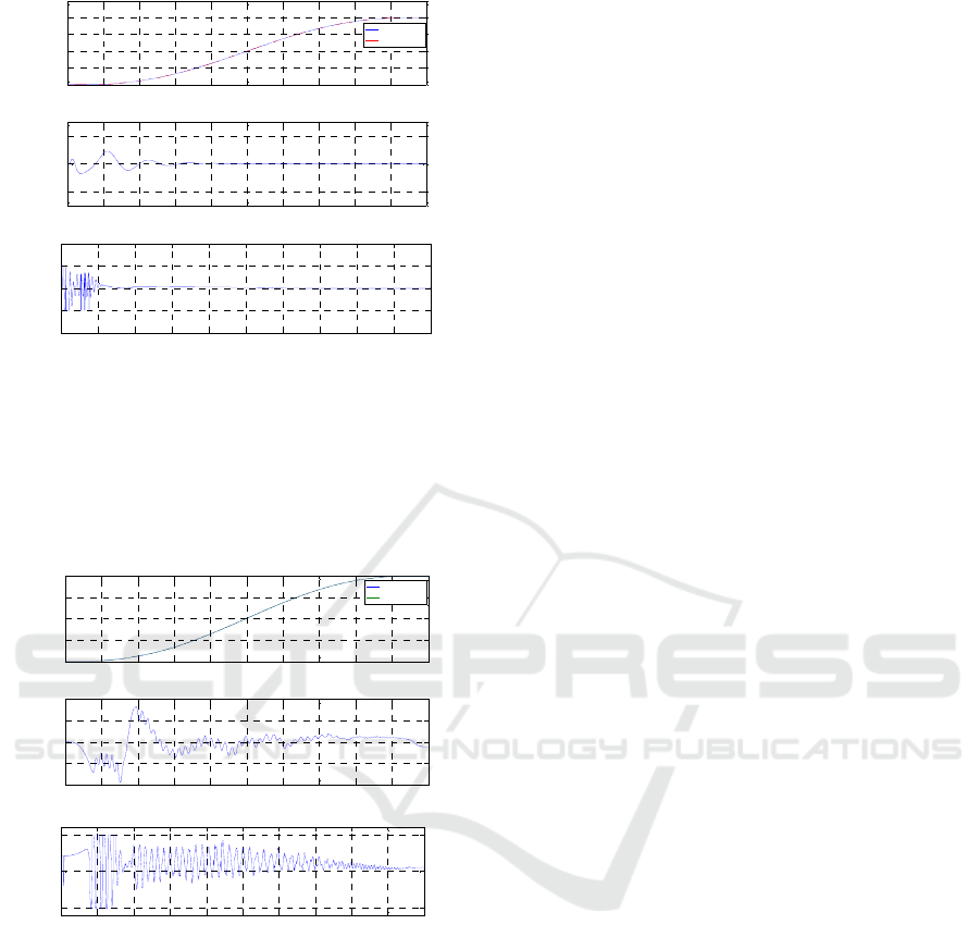
4.1 Simulations of Path Control
The simulation of the path tracking servo control of
a fifth order polynomial with stroke of 200 mm in
2 sec controlled by FSBASMC+Hinf is
implemented, as shown in Figure 4, where the
position control response, the control error and the
control input are schematically described. The
simulation responses by FSBASMC+Hinf are shown
in Figure 4(a). From Figure 4(b), the tracking error
is bounded and well converged. Figure 4(c) shows
the control signal of FSBASMC+Hinf.
ICINCO 2016 - 13th International Conference on Informatics in Control, Automation and Robotics
402
0 0.2 0.4 0.6 0.8 1 1.2 1.4 1.6 1.8 2
0
50
100
150
200
250
(a)
position (mm)
Time (sec)
Target
Experiment
0 0.2 0.4 0.6 0.8 1 1.2 1.4 1.6 1.8 2
-2
0
2
(b)
error(mm)
Time (sec)
0 0.2 0.4 0.6 0.8 1 1.2 1.4 1.6 1.8 2
-10
-5
0
5
10
(c)
Voltage(V)
Time (sec)
Figure 4: Simulation results of the rodless pneumatic
actuator system under an asymmetrical load for a fifth
order polynomial path with stroke of 200 mm in 2 sec: (a)
position control response (b) control error (c) control
input.
4.2 Experiments of Path Control
0 0.2 0.4 0.6 0.8 1 1.2 1.4 1.6 1.8 2
0
50
100
150
200
Time (sec)
position (mm)
(a)
Target
Experiment
0 0.2 0.4 0.6 0.8 1 1.2 1.4 1.6 1.8 2
-1
-0.5
0
0.5
1
(b)
error(mm)
Time (sec)
0 0.2 0.4 0.6 0.8 1 1.2 1.4 1.6 1.8 2
-5
0
5
(c)
Voltage(V)
Time (sec)
Figure 5: Experimental results of the rodless pneumatic
actuator system under an asymmetrical load for a fifth
order polynomial path with stroke of 200 mm in 2 sec: (a)
position control response (b) control error (c) control
input.
In the experiments, the position responses, tracking
errors and control inputs for the rodless pneumatic
actuator system under an asymmetrical load by a
fifth order polynomial with stroke of 200 mm in
2 sec are shown in Figure 5. Figure 5(b) shows the
maximum tracking error can reach about 0.9mm.
The control inputs are shown in Figure 5(c). From
Figure 5(c), control input signals fluctuate form +5
volts to -5 Volts. Therefore, the desired tracking
performance can be achieved.
5 CONCLUSIONS
In this study, a rodless pneumatic actuator system
under an asymmetrical load has been developed and
successfully implemented for real-time path tracking
servo control by the feedback measurement system.
The dynamic models and the control strategies are
built in Matlab software. The real-time control
measurement system is established by PC-based
system. For further confirming the proposed system,
the 5-th order polynomial path is implemented.
Finally, the simulation and experimental results
demonstrate that the proposed method is validated to
apply in the real-time path tracking control of the
pneumatic servo system under the asymmetrical
vertical load.
ACKNOWLEDGEMENTS
This research was sponsored by Ministry of Science
and Technology, Taiwan under the grant MOST
104-2218-E-035 -017.
REFERENCES
Oyama, O. et al, 1990. Model reference adaptive control
for a pneumatic cylinder servo system. Journal of the
Japan Hydraulic Pneumatic Society, Vol. 21, pp. 182-
186.
Gyeviki, J. et al, 2005. Sliding Modes Application in
Pneumatic Positioning. Proceedings of the 2005 IEEE
International Conference on Mechatronics, Taipei,
Taiwan, pp. 964-969, July 10-12.
Chiang, M. H., Lin, H. T., 2011. Development of a 3D
parallel mechanism robot arm with three vertical-axial
pneumatic actuators combined with a stereo vision
system. Sensors, Vol. 11, pp. 11476-11494.
The Real-time Tracking Servo Control of a Rodless Pneumatic Actuator System under an Asymmetrical Load via the Feedback
Measurement System
403
