
Development of a Simulink Dynamic Matrix Control (DMC) Block for
Use with an RCP System and Its Application to Motor Control
Young Sam Lee, Jinsuk Choi, Sugkil Seo and Yeong Sang Park
Department of Electrical Engineering, Inha University, Incheon, Korea
Keywords:
Dynamic Matrix Control, Rapid Control Prototyping, DC Motor Control, Realtime Control.
Abstract:
In this paper, we present the implementation method of a Simulink block for dynamic matrix control (DMC)
that can be used in a rapid control prototyping (RCP) environment and consider the speed control of a DC mo-
tor using the developed DMC block. Firstly, we introduce a lab-built RCP system briefly. Secondly, we present
a method to implement the DMC block using C-language, which enables DMC algorithm to be represented
in a library block that can be used in Simulink environment. Finally, we use the developed DMC block for
the speed control of a DC motor, through which we show that the DMC-based control system can be easily
implemented and it can be applied to real-time control of systems with relatively fast sample rates.
1 INTRODUCTION
Predictive control is the optimization-based control
strategy, where we try to find the optimal future con-
trol trajectory that minimizes the cost function on the
future response predicted using the model informa-
tion of the controlled system. Predictive control is a
computation-intensive control method because it has
to solve the constrained optimization problem at each
sample time.
In predictive control, we need to construct a pre-
dictor to predict the future response of a controlled
system. A certain predictive control utilizes the state
space model for the predictor (Lee et al., 1994) while
the other predictive controls are based on the trans-
fer function model (Clarke et al., 1987a; Clarke et al.,
1987b) or on a step response model (Garcia and Mor-
shedi, 1986). Dynamic matrix control, one of many
predictive control methods, needs just a step response
to construct a predictor while other predictive con-
trol requires a state space model or a transfer function
model, which is not available in real situations. In that
respect, DMC has good practical value.
Merits of the predictive control include the sys-
tematic consideration of the input/output constraint
of the system and easy extension of its principle to
multivariable systems. The ability of handling the in-
put/output constraint comes from the fact that the
computation of the control value is formulated into
an optimization problem subject to constraints. In
most cases, the optimization problems reduce to the
quadratic programming (QP) problem. The solution
to the quadratic programming is obtained after some
complicated procedures and hence the predictive con-
trol is computation-intensive methodology. Due to
this fact, predictive controls have been majorly used
in process control area, where systems are fairly slow
in response. Some mathematical software, such as
Matlab, provides a command to solve the quadratic
programming.
Despite the merits mentioned above, it is not easy
for one to apply the predictive control to real control
systems. Firstly, one needs the C-code solution to the
QP problem for the implementation of the predictive
control. qpOASES, which is an open-source QP prob-
lem solver, can be good candidate solution to the QP
problem (Ferreau et al., 2014). Even with the C-code
solution, still the implementation of predictive control
in C-code is not an easy task for beginning engineers.
Recently, implementation of the control system is
done through RCP systems instead of conventional
manual coding. The most representative RCP system
includes the one based on Matlab/Simulink. One can
construct a controller model using the function blocks
supported in Simulink and then translate the con-
troller model into C-codes through the automatic code
generation tool. The generated codes can be com-
piled and downloaded onto a micro-controller board
for realtime execution. A certain RCP system does
not use the code generation approach. In that system,
the Simulink controller model perform as a real-time
controller (Lee et al., 2012). One can focus on the de-
Lee, Y., Choi, J., Seo, S. and Park, Y.
Development of a Simulink Dynamic Matrix Control (DMC) Block for Use with an RCP System and Its Application to Motor Control.
DOI: 10.5220/0005958004130420
In Proceedings of the 13th International Conference on Informatics in Control, Automation and Robotics (ICINCO 2016) - Volume 1, pages 413-420
ISBN: 978-989-758-198-4
Copyright
c
2016 by SCITEPRESS – Science and Technology Publications, Lda. All rights reserved
413

velopment of the control algorithm using the block
diagram editing and doesn’t have to be worried about
the input/output peripheral handling based on manual
coding.
In this paper, we propose a method to construct a
function block for the dynamic matrix control for use
with RCP system based on Simulink. The presented
block is implemented in C-code and thus has good
computation property. Due to this fact, the resultant
control can be applied to systems with relatively fast
sample rate. The DMC block can also translated into
C-code through the automatic code generation pro-
cess. In this paper, we will use a lab-built RCP en-
vironment for the application of the proposed DMC
block.
The paper is structured as follows: In Section 2,
we give brief introduction to a lab-built RCP system.
In Section 3, we present the method to construct a
DMC block. In Section 4, we summarize the proce-
dures about how to construct a speed control system
for a DC motor using the DMC block. Finally in Sec-
tion 5, we make conclusions on the presented results.
2 INTRODUCTION OF THE DAQ
RCP
Rapid control prototyping (RCP) system is a kind of
development environment that is used for the design,
development, and verification of the controller pro-
totype in an efficient way. Generally RCP systems
consist of a block diagram based modeling program
such as Simulink, library blocks to handle the hard-
ware input/output peripherals, automatic C-code gen-
erator, realtime target computer, and a host computer
communicating with the target computer. The design
and the simulation of the controller are done under
Simulink. If the simulation result is satisfactory, the
controller is constructed by using the input/output
peripheral library blocks. After the code generation
of the controller model, the compiled executable is
downloaded to a realtime target computer and the re-
altime control experiment is performed. While the ex-
periment is being performed, one can monitor signals
using a host computer connected to a target computer.
With the help of the input/output peripheral block li-
brary and code generation tool supported in the RCP
system, the controller designers have only to focus on
the algorithm itself without worrying about the error
prone manual coding.
Several RCP systems are available commer-
cially in the market. Matlab/Simulink is the most
well known and widely used among those sys-
tems. Realtime Workshop (RTW), the add-on prod-
uct of Simulink, generates C-code for the block
diagram-based model constructed by Simulink (Inc.,
2005b). Embedded coder, another add-on product of
Simulink, generates C-code specific to a certain em-
bedded processor and thus reduce the time for the de-
velopment (Inc., 2005a). Matlab/Simulink and RTW
are open architecture and thus several lab-developed
RCP systems for custom-developed hardware have
been proposed in academia (Rebeschieß, ; Hong et al.,
2000; Lee et al., 2004; Hercog and Jezernik, 2005;
Bucher and Balemi, 2006; Lee et al., 2012). Further-
more, several researches related with the application
of RCP system are published (Lin et al., 2006; Ken-
nel, 2006).
In this paper, we use the RCP system proposed in
(Lee et al., 2012). The RCP system proposed in (Lee
et al., 2012) utilizes a DAQ board with high speed
USB communication interface and Matlab/Simulink.
Because it uses a DAQ board with a microcontroller
as a basic component, we will call the system as
the DAQ RCP throughout the paper. The DAQ RCP
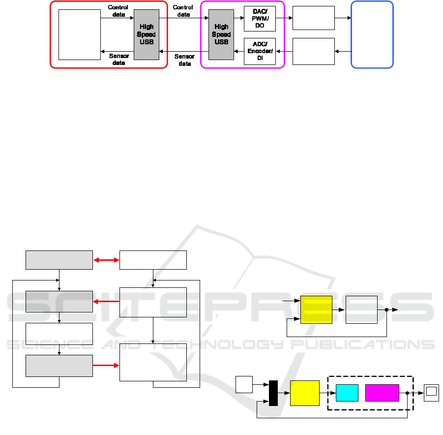
system consists of two subsystems as in Figure 1.
The first subsystem is a PC system on which Mat-
lab/Simulink is running and the second subsystem is
a DAQ board with high speed USB interface. The PC
and the DAQ board communicates the data (control
data and sensor data) with each other throughtheUSB
communication. Unlike the conventional RCP system
where the control algorithm is automatically gener-
ated in C-code from the Simulink controller model,
the DAQ RCP system has a feature that the Simulink
controller model acts as a realtime controller without
code generation. Measurement of the sensor data and
the application of the control data to output peripher-
als are taken care of by the DAQ unit with a microcon-
troller. Figure 2 Figure 2 is the flowchart that shows
how the control is performed. Each stage in the flow
chart can be summarized as follows:
S1: The DAQ unit measures all the required sensor
data and sends them to the PC through USB com-
munication.
S2: Simulink running on the PC receives the data
sent from the DAQ unit.
S3: Simulink performs the control computation using
the received sensor data.
S4: Simulink sends the computed control data to the
DAQ unit.
S5: The DAQ unit applies the received control data
from the PC to corresponding output peripherals
(DAC, PWM, etc).
It is noted that all the tasks performed in the DAQ unit
are handled by the microcontroller. As mentioned in
ICINCO 2016 - 13th International Conference on Informatics in Control, Automation and Robotics
414
Driver
DriverDriver
Driver
Circuit
CircuitCircuit
Circuit
PC (Matlab/Simulink)
PC (Matlab/Simulink)PC (Matlab/Simulink)
PC (Matlab/Simulink)
Control
ControlControl
Control
algori thm
algori thmalgori thm
algori thm
Sensor
SensorSensor
Sensor
Interf ace
Interf aceInterf ace
Interf ace
Circuit
CircuitCircuit
Circuit
Real
RealReal
Real
P
PP
Pl
ll
la
aa
an
nn
nt
tt
t
Custom-built DAQ Unit
Custom-built DAQ UnitCustom-built DAQ Unit
Custom-built DAQ Unit
Figure 1: The conceptual diagram on a lab-built DAQ RCP system.
(Lee et al., 2012), the DAQ RCP system can handle
the control system with sample rates of up to 2 KHz.
Therefore, a good portion of control experiments per-
formed in undergraduate or graduate courses can be
supported by the DAQ RCP system. It provides use-
ful input/output function blocks that can handle in-
put/output peripherals in a graphical manner. The rep-
resentative input/output function blocks include an
encoder counter block, a digital input block, an ADC
block, a PWM block, a digital output block, and a
DAC block.
Initialization Initialization
Reception of the
sensor data from the
DAQ board
Control computation
Trasmission of the
control data to
the DAQ board
Sensor data
measurement
Transmission of the
data to the PC
Reception of the control
data from the PC
Application of the
received data to
peripherals
L
L
L
L
o
o
o
o
o
o
o
o
p
p
p
p
PC (Simulink) DAQ Board
USB
USB
USB
L
L
L
L
o
o
o
o
o
o
o
o
p
p
p
p
S1
S2
S3
S4
S5
Figure 2: The flow chart of the DAQ RCP system proposed
in (Lee et al., 2012).
3 IMPLEMENTATION OF A DMC
BLOCK
In this section, we present how to construct the DMC
function block using a C-code S-function. The S-
function provides a powerful mechanism for extend-
ing the capabilities of the Simulink environment. The
S-function is a computer language description of a
Simulink block written in Matlab, C, C++, or For-
tran. One can write an S-Function to describe a user-
defined function block. We use a lab-built DAQ RCP
system in this paper, where we don’t have to generate
the C-code for the model. However, to speed up the
computation, we develop the DMC block in C-code
S-function.
Figure 3 shows the control system diagram that
adopts the DMC as a control method. The main pur-
poses of this paper are as follows: to make the DMC
be used in Simulink environment by developing the
DMC function block in a C-code S-function; to make
the DMC be used in the RCP system using the devel-
oped DMC block; to give the environment in which
one can implement the realtime dynamic matrix con-
trol of real systems easily.
If we construct the speed control system for a DC
motor using the DMC block in the DAQ RCP system,
the controller model will look like Figure 4. To mea-
sure the speed of a motor and to generate the PWM
signal to a motor driver, we will use the encoder block
and the PWM block provided by the DAQ RCP sys-
tem.
DMC System
r
y
Figure 3: The block diagram of the DMC-based control sys-
tem.
DMC EncoderPWM
Ref
Mux
Figure 4: The block diagram of the DC motor control sys-
tem implemented in Simulink using the DAQ RCP.
The implementation of the DMC block includes
three stages. Firstly, we have to implement the solu-
tion to the QP problem. Secondly, we have to imple-
ment the DMC algorithm using the obtained QP so-
lution. Finally we define the DMC block in a C-code
S-Function.
3.1 Implementation of the QP solution
The most essential algorithm to implement the predic-
tive control may be the solution algorithm to the QP
problem. The dynamic matrix control is one of pre-
dictive control methods and thus we need to have a
C-code solution to the QP problem to implement the
Development of a Simulink Dynamic Matrix Control (DMC) Block for Use with an RCP System and Its Application to Motor Control
415

DMC block. In this paper, we adopt the method pre-
sented in (Lee et al., 2014) to develop the DMC block.
The general QP problem is stated as follows:
min
x
1
2
x
T
Px+ q
T
x subject to Ax ≤b. (1)
With P > 0, the problem reduces to a convex opti-
mization and the unique and global solution is always
guaranteed. The QP problem to be solved in predic-
tive control satisfies P > 0. So we use the solution
to the QP problem for the specific case P > 0. As
explained in (Lee et al., 2014), the QP problem can
be equivalently changed into the NNLS(Nonnegative
least-squares) problem after a series of equivalent
transformations. Therefore one can obtain the solu-
tion to the QP problem buy solving the following
NNLS problem:
NNLS: min
d
kQd −rk subject to d ≥0, (2)
where
Q =
¯
A
T
¯
b
T
, r =
0
.
.
.
0
1
and
¯
A = −AVS
−1
,
¯
b = −A¯q −b, ¯q = P
−1
q. Matri-
ces V and S are obtained by performing the singular
value decomposition (SVD) of
√
P and they satisfy
√
P = USV
T
. Letting the solution to the NNLS prob-
lem given in (2) be d
∗
, the solution to the original QP
problem given in (1), x
∗
, can be given as follows:
x
∗
= VS
−1
¯
A
T
d
∗
(1−
¯
b
T
d
∗
)
− ¯q
The following computations should be done to obtain
the solution to the QP problem given the matrices P,
q, A, and b:
(a) matrix addition, subtraction, and multiplication
(b) solving the NNLS problem
(c) singular value decomposition of
√
P
(d) matrix inversion to obtain P
−1
Computation for (a) can be easily programmed in C
code. Solving the NNLS problem in (b) can also be
implemented in C code using the algorithm presented
in (Lawson and Hanson, 1974). For the computation
of (c) and (d), we need to compute the square root
of a matrix, singular value decomposition, and matrix
inversion, which are somewhat complicated process.
However, the matrix P is a constant matrix as long as
the system model used to design the predictive control
does not change. Therefore, we don’t have to imple-
ment the C-code to compute (c) and (d). Instead, we
use Matlab to compute (c) and (d) and then use the
obtained results by generating array data for them in
a separate header file. One can use the Matlab com-
mand ‘fprintf’ for that purpose.
3.2 Implementation of the DMC
The DMC, one of predictive controls, utilizes the step
response of a system to construct a predictor. The
DMC solves the following optimization problem sub-
ject to constraints at every sample time to compute the
control value:
Minimize J =
N
p
∑
j=1
kw
k+ j
− ˆy
k+ j
k
2
+
N
c
−1
∑
j=0
k∆u
k+ j
k
2
Λ
(3)
subject to u
min
≤ u
k+ j
≤ u
max
,
∆u
min
≤ ∆u
k+ j
≤ ∆u
max
,
j = 0,1,··· ,N
c
−1. (4)
The subscripts used in variables denote the time step
and k denotes the current time step. Letting u be
the control value, u
k+ j
denotes the control value at
the moment j step away from the current time. w
is the reference input, ˆy is the predicted output, ∆u
is the control increment, N
p
is the prediction hori-
zon, and N
c
is the control horizon. Generally it holds
that N
p
≥ N
c
. Λ, a diagonal matrix, is the weight-
ing on the control increment. Hence the square of
the weighted norm can be represented as k∆u
k+ j
k
2
Λ
=
∆u
T
k+ j
Λ∆u
k+ j
. In the DMC, the control increment is
obtained up to the step k + N
c
−1 at every sample
time. However, only ∆u
k
is used to obtain the control
value, which is given as
u
k
= u
k−1
+ ∆u
k
.
In the DMC, the predicted output from the current
step to the moment which is N
p
steps away is given
by
ˆ
Y
k
= G∆U
k
+ f
k
, (5)
where
ˆ
Y
k
= [ ˆy
T
k+1
ˆy
T
k+2
··· ˆy
T
k+N
p
]
T
∆U
k
= [∆u
T
k
∆u
T
k+1
··· ∆u
T
k+N
c
−1
]
T
and G is a prediction matrix consisting of step re-
sponse data. f
k
is the free response, which can be
viewed as the contribution of the past data to the fu-
ICINCO 2016 - 13th International Conference on Informatics in Control, Automation and Robotics
416
ture output, is given by
G =
g
1
0 ··· 0
g
2
g
1
··· 0
.
.
.
.
.
.
.
.
.
.
.
.
g
N
c
g
N
c
−1
··· g
1
.
.
.
.
.
.
.
.
.
.
.
.
g
N
p
g
N
p
−1
··· g
N
p
−N
c
+1
, (6)
f
k
=
¯y
k
¯y
k
.
.
.
¯y
k
+ M
∆u
k−1
∆u
k−2
.
.
.
∆u
k−(N−1)
+
h
2h
.
.
.
N
p
h
u
k−N
, (7)
where
M =
g
2
−g
1
g
3
−g
2
··· g
N
−g
N−1
g
3
−g
1
g
4
−g
2
··· g
N+1
−g
N−1
.
.
.
.
.
.
.
.
.
.
.
.
g
N
p
+1
−g
1
g
N
p
+2
−g
2
··· g
N
p
+N−1
−g
N−1
and ¯y
k
is the measurement of the output, g
i
is the step
response value at time step k = i obtained by apply-
ing a step input to the system at time k = 0. In case of
multivariable system with n
u
inputs and n
y
outputs, g
i
is a n
y
×n
u
matrix (Lundstrom et al., 1995). N is the
number of steps taken to reach the steady state when
the system is stable or it includes an integrating pro-
cess. In case of systems with integrating process, the
output at the steady state will show a constant slope
with time. At steady state, h = g
i+1
−g
i
. It holds that
h = 0 for stable systems and and h 6= 0 for systems
with integrating process. G does not have any sub-
script because it is constant. Let’s define the future
reference trajectory as follows:
W
k
= [w
T
k+1
w
T
k+2
··· w
T
k+N
p
]
T
.
Then, as explained in (Lee et al., 2014), obtaining
DMC control value reduces to a QP problem with ∆U
k
being an optimization variable. Here, the matrices P,
q, A, and b are given as follows:
P = G
T
G+ Ξ, q = −(W
k
− f
k
)
T
G,
A =
I
D
−I
D
I
L
−I
L
,b =
I
V
u
max
−I
V
u
min
I
V
(u
max
−u
k−1
)
−I
V
(u
min
−u
k−1
)
(8)
where
Ξ = diag{Λ,Λ,··· ,Λ}, I
D
=
I
m
0 ··· 0
0 I
m
··· 0
.
.
.
.
.
.
.
.
.
.
.
.
0 0 ··· I
m
,
I
L
=
I
m
0 ··· 0
I
m
I
m
··· 0
.
.
.
.
.
.
.
.
.
.
.
.
I
m
I
m
··· I
m
, I
V
=
I
m
I
m
.
.
.
I
m
and these matrices have appropriate dimensions de-
pending on the prediction horizon and the control
horizon. As shown in (8), among the matrices P, q,
A, b pertaining to the QP problem to obtain the DMC
control value, P and A remain unchanged while q and
b change at every step. Therefore, we can obtain the
data related with P and A offline using Matlab and
then generate a C-code header file containing the data.
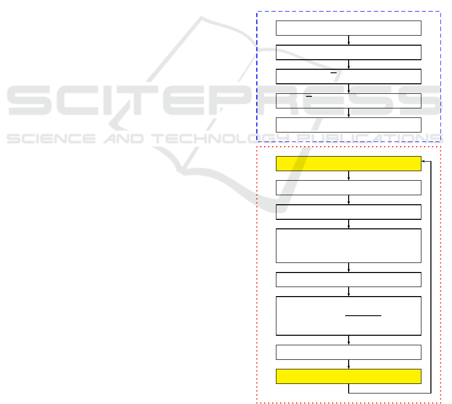
Compute G from step response data
P = G
T
G + Ξ
√
P, P
−1
계산
SVD(
√
P = USV
T
)→ Compute S and V
¯
A = −AVS
−1
offlineonline
Measure the output values
Compute W
k
, f
k
, and b
k
q
k
= −(W
k
− f
k
)
T
G, ¯q
k
= P
−1
q
k
¯
b
k
= −A¯q
k
− b
k
, Q
k
=
¯
A
T
¯
b
T
k
d
∗
k
= NNLS(Q
k
)
∆U
∗
k
= VS
−1
¯
A
T
d
∗
k
(1 −
¯
b
T
k
d
∗
k
)
− ¯q
k
u
k
= u
k−1
+ ∆u
∗
k
Apply u
k
to the system
Figure 5: The flow chart of the algorithm.
Development of a Simulink Dynamic Matrix Control (DMC) Block for Use with an RCP System and Its Application to Motor Control
417
Furthermore, the generation of q and b should be done
online. To explicitly denote that q and b vary at each
time, let’s denote them by q
k
and b
k
, respectively. Fig-
ure 5 shows the flowcharts for the offline computation
part and the online computation part. We can imple-
ment the DMC algorithm by translating the algorithm
in the flowchart in C-code.
3.3 Implementation of the DMC Block
We can implement the DMC algorithm presented
above in C-code. However, it is never easy for stu-
dents or engineers who are not familiar with control
theory to implement the DMC algorithm in C-code
by themselves. If we can provide a function block for
DMC that can be used in a Simulink environment, one
has only to copy the DMC block to build a controller
in a graphical manner. In this respect, we implement
the DMC function block that can be used in Simulink.
Matlab allows the users to define a custom function
block through the S-function. In an S-function, one
has to define a block initialization function, a output
function, a termination function, etc to describe the
every aspect of a block. As in the concept diagram
given in Figure 4, the inputs to the DMC block are the
reference input and the measured output and the out-
put of the DMC block is the control value. The rela-
tionship between the inputs and output was described
in the previous subsection.
4 IMPLEMENTATION OF THE
DMC-BASED VELOCITY
CONTROL FOR A DC MOTOR
In this section, we will deal with the realtime dynamic
matrix control of the speed of a DC motor by con-
structing a controller using the DMC block in the lab-
built RCP environment.By doing so, we will illustrate
that the DMC-based control system can be easily con-
structed and can be applied to systems with somewhat
fast sample rates. We use a 150W Maxon DC motor
in the experiment. It has a rotary incremental encoder
with the resolution of 500 PPR to measure the posi-
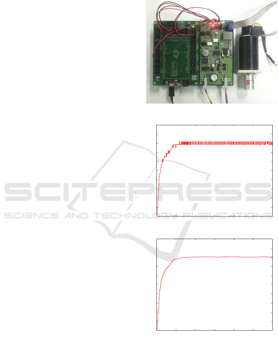
tion and speed of a rotor. Figure 6 shows the experi-
mental setup, where the left part is a DAQ unit with
an Arduino Due being a main microcontroller and the
center is a DC motor driver using an H bridge, and the
right part is a Maxon DC motor. The DAQ unit is con-
nected to the PC through the USB interface. We use
the unipolar complementary PWM to drive the motor
driver.
Figure 6: The experimental set for the speed control of a DC
motor.
0 0.05 0.1 0.15 0.2 0.25 0.3
0
2
4
6
8
10
12
14
16
18
20
time(sec)
velocity(rad/sec)
Step response
Figure 7: A step response (raw data).
0 0.05 0.1 0.15 0.2 0.25 0.3
0
2
4
6
8
10
12
14
16
18
20
time(sec)
velocity(rad/sec)
Step response
Figure 8: A step response after post processing.
4.1 Acquisition of the Step Response
Data
In order to construct a DMC-based controller, we first
have to obtain the step response data of a system. For
ICINCO 2016 - 13th International Conference on Informatics in Control, Automation and Robotics
418
(Due RCP)
ADC0
1
2
3
Maxon Motor
voltage
theta
dot theta
s+12
12
s+30
30
−K−
−K−
DMC
EclDmc
2
Figure 9: DC motor speed control system implemented using a developed DMC block.
this purpose, we applied a step input of 5 volt to the
motor and measured the resultant speed. We obtained
a unit step response through the normalization (i.e.,
division by 5). The sample rate of the Simulink model
is set to 1 KHz, which is relatively fast for DMC-
based control system.
It is not easy to get the reliable step response data
through just one experiment. Figure 7 shows the step
response data that has not gone through any post pro-
cessing. The rotary encoder has limited resolution and
thus quantization noise is clearly seen in the figure.
We performed 30 experiments and we compute the
average. Furthermore, we post-processed the data us-
ing a noncausal filter, which is supported by the Mat-
lab command ‘filtfilt’, to get smoother step response
data. Figure 8 shows the step response data that has
gone through this post-processing.
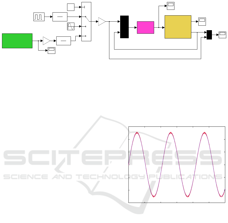
4.2 DMC-based Speed Control
We can decide the horizon N in (7) from the moment
when the step response reaches the steady state. From
Figure 8, it is seen that the step response goes into the
steady state from t = 0.3. Because the sample time
is 1 ms, we chose N = 0.3/0.001 = 300. The con-
trol horizon and the prediction horizon were chosen
to be N
c
= 3, N
p
= 3. We set the DC power supply
so that its output is 10 V. This leads to u
max
= 10
and u
min
= −10. Figure 9 shows the Simulink speed
control model implemented using the proposed DMC
bloc. It is constructed so that we can choose one out
of three possible reference trajectories, which are a
square wave, a sinusoidal wave, and external input
coming from the potentiometer. In Figure 9, a sinu-
soidal wave is chosen as the speed reference input.
Figure 10 shows the experimental result of the
DMC-based speed control with the sinusoidal wave
being a reference input. The blue line is the reference
input, the red line is the actual speed of the motor. It
is clearly seen that the motor speed tracks the speed
reference successfully.
The sample rate of this experiment is 1 KHz. Con-
sidering that the predictive control has been majorly
applied to sluggish systems, this sample rate can be
said fairly fast. This fast sample rate can be made han-
dled because the DMC block presented in this paper
is implemented through a C-cod S-function. Further-
more, we see that the DMC method can be easily im-
plemented by using the presented DMC block in the
RCP environment.
0 1 2 3 4 5 6
−150
−100
−50
0
50
100
150
time(sec)
velocity(rad/sec)
Motor velocity
Figure 10: Speed control response of DMC.
5 CONCLUSIONS
In this paper, we developed a Simulink function block
for the dynamic matrix control and applied the devel-
oped block to the speed control of a DC motor. For
the development of a DMC block, we firstly presented
how to program a solution to the quadratic program-
ming in C language. We also presented how to im-
plement the DMC algorithm using the presented solu-
tion. Furthermore, we implemented a DMC block that
can be used in Simulink environment using a C-code
S-function. By developing a DMC function block for
Simulink and using it in RCP system, the a realtime
dynamic matrix control of a system can be easily im-
plemented. In order to illustrate the usefulness of the
Development of a Simulink Dynamic Matrix Control (DMC) Block for Use with an RCP System and Its Application to Motor Control
419

proposed DMC block, we applied it to the speed con-
trol problem of a DC motor. Through the experiment,
we showed that the proposed DMC block can be ap-
plied to the realtime control system with relatively
fast sample rate.
ACKNOWLEDGEMENTS
This research was supported by the MSIP(Ministry
of Science, ICT and Future Planning), Korea, under
the ITRC(Information Technology Research Center)
support program (IITP-2016-H8601-16-1003) super-
vised by the IITP(Institute for Information & commu-
nications Technology Promotion)
REFERENCES
Bucher, R. and Balemi, S. (2006). Rapid controller proto-
typing with Matlab/Simulink and Linux. Control En-
gineering Practice, 14:185–192.
Clarke, D. W., Mohtadi, C., and Tuffs, P. S. (1987a). Gen-
eralized predictive control-Part I. The basic algorithm.
Automatica, 23(2):137–148.
Clarke, D. W., Mohtadi, C., and Tuffs, P. S. (1987b). Gen-
eralized predictive control-Part II. Extensions and in-
terpretations. Automatica, 23(2):149–160.
Ferreau, H. J., Kirches, C., Potschka, A., Bock, H. G., and
Diehl, M. (2014). qpOASES: a parametric active-set
algorithm for quadratic programming. Math. Prog.
Comp., 6:327–363.
Garcia, C. E. and Morshedi, A. M. (1986). Quadratic
programming solution of dynamic matrix control
(QDMC). Chem. Eng. Commun., 46:73–87.
Hercog, D. and Jezernik, K. (2005). Rapid control proto-
typing using Matlab/Simulink and a DSP-based motor
controller. Int. J. Engng Ed., 21(3):1–9.
Hong, K. H., Gan, W. S., Chong, Y. K., Chew, K. K., Lee,
C. M., and Koh, T. Y. (2000). An integrated environ-
ment for rapid prototyping of DSP algorithms using
and Texas Instruments’ TMS320C30 . Microproces-
sors and Microsystems, 24(7):349–363.
Inc., T. M. (2005a). Real-time workshop embedded code
user’s guide (ecoder
ug.pdf), Version 4.
Inc., T. M. (2005b). Real-time workshop user’s guide
(rtw
ug.pdf), Version 6.
Kennel, R. (2006). Improved direct torque control for in-
duction motor drives with rapid prototyping system.
Energy Conversion and Management, 47:1999–2010.
Lawson, C. L. and Hanson, R. J. (1974). Solving least
squares problems. Prentice-Hall, Englewood Cliffs,
New Jersey.
Lee, J. H., Morari, M., and Garcia, C. E. (1994). State-space
interpretation of model predictive control. Automat-
ica, 30(4):707–717.
Lee, W., Shin, M., and Sunwoo, M. (2004). Target-identical
rapid control prototyping platform for model-based
engine control. Proc. Instn Mech. Engrs Part D, J.
Automobile Engineering, 218:755–765.
Lee, Y. S., Gyeong, G. Y., and Park, J. H. (2014). QP So-
lution for the implementation of the predictive con-
trol on microcontroller systems and its application
method. Journal of Institute of Control, Robotics, and
Systems (in Korean), 20(9):908–913.
Lee, Y. S., Yang, J. H., Kim, S. Y., Kim, W. S., and Kwon,
O. K. (2012). Development of a rapid control protot-
pying system based on Matlab and USB DAQ boards.
Journal of Institute of Control, Robotics, and Systems
(in Korean), 18(10):912–920.
Lin, C. F., Tseng, C. Y., and Tseng, T. W. (2006). A
hardware-in-the-loop dynamics simulator for motor-
cycle rapid controller prototyping. Control Engi-
neerning Practice, 14:1467–1476.
Lundstrom, P., Lee, J. H., Morari, M., and Skogestad, S.
(1995). Limitations of dynamic matrix control. Com-
puters Chemical Engineering, 19(4):409–421.
Rebeschieß, S. MIRCOS-Microcontroller-based real time
control system toolbox for use with Matlab/Simulink.
In Proc. IEEE Int. Symp. Computer Aided Control
System Design, pages 267–272, 1999.
ICINCO 2016 - 13th International Conference on Informatics in Control, Automation and Robotics
420
