
roboBAN: A Wireless Body Area Network for Autonomous Robots
Lukas Gisin, Hans Dermot Doran and Juan-Mario Gruber
Institute of Embedded Systems, Zurich University of Applied Sciences, Technikum Str. 9, 8401 Winterthur, Switzerland
Keywords: Wireless Body Area Network (WBAN), Wireless Sensor Network (WSN), Ultra-Low Power (ULP), Energy
Harvesting, Autonomous Robots.
Abstract: In this paper we describe a Wireless Body Area Network (WBAN) designed and implemented for an
autonomous robot. We concentrate in particular on the ultra-low power radio aspects. We compare and
contrast standard and proprietary solutions before deciding on a proprietary radio SoC in the 2.4 GHz. band.
We describe the protocol implementation and tests on both a test jig and on the robot itself at sampling rates
of up to 1 kHz. and conclude that the principle of a robot based WBAN works well. We also show that the
proposed WBAN is suitable for connection by nodes employing energy harvesting.
1 INTRODUCTION
1.1 Motivation
Much work has gone into the research and
development of autonomous robots. The focus of
this research effort is to understand how to build
such robots and get them functioning in real-world
use cases. There are also considerable engineering
challenges to be surmounted to get such robots ready
for market including issues such as power and
weight distribution. If we take the use-case of a
payload carrying robot then the robot needs to be
aware of the dynamics of the payload which requires
communication between the payload, or its harness,
and the robot. For reasons of security, compatibility
and bandwidth, this communication should not be
carried over the in-robot control network but must
be carried over a separate channel. Any power the
payload may require, including that needed to
communicate with the robot, should not be sourced
from the robot. The communication network must
reflect that fact.
In this body of work we propose a Wireless
Body Area Network (WBAN) as a communication
network for such ancillary information providers,
although we use a system critical component as the
first participant. As a second novelty we follow an
aggressive power policy by stipulating that the nodes
find their own power through energy harvesting
techniques. In this paper we restrict ourselves to
describing the networking aspects, physical and data
link layer, of the proposed WBAN.
The remainder of this paper is structured
accordingly: We end this chapter by introducing the
target application. In the next section we discuss
issues around WBAN and the application and
describe state of the art radio devices for the typical
WBAN protocols before describing the concept we
decided on. In Section 3 we discuss the results of the
measurements on both a test jig and on the target
robot and we finish, in the final section, with
conclusions and further work.
1.2 Target Application
The target application for this work is the quadruped
StarlETH (Hutter 2012) developed at the
Autonomous System Lab of the Swiss Federal
Institute of Technology, ETH Zürich. This medium-
dog-sized robot, Figure 1, achieves stable
locomotion especially on rough terrains where other
humanoid or wheel-based robots have difficulties.
StarlETH weighs about 25 kg, can carry a payload
of up to 25 kg and has a maximum speed of > 2
km/h. Energy autonomy of approx. 1 hour is
currently reached at an average power consumption
of 300 W (ASL, 2015.) The StarlETH is a research
object; a further version is currently undergoing
advanced development for use in such environments
as oil rigs or in copper mines as an inspection robot.
Gisin, L., Doran, H. and Gruber, J-M.
roboBAN: A Wireless Body Area Network for Autonomous Robots.
DOI: 10.5220/0005968700490060
In Proceedings of the 13th International Conference on Informatics in Control, Automation and Robotics (ICINCO 2016) - Volume 2, pages 49-60
ISBN: 978-989-758-198-4
Copyright
c
2016 by SCITEPRESS – Science and Technology Publications, Lda. All rights reserved
49

Figure 1: Quadruped robot StarlETH with 3D force
sensors in the foot.
To enable adaptive motion control each foot is
equipped with a high precision optical three axis
(3D) force sensor (Opto Force, 2015.) The sensor is
installed within a robust rubber sphere enclosure to
sense contact force, detect ground contact and, at the
same time, dampen the impact of the foot hitting the
ground. Currently only the binary signal denoting
ground-contact as true or false is used but the sensor
was built into the robot with the idea of detecting the
microstructure of the terrain in future work. The
sampling rate is that of the force control loop, 1 kHz.
The force sensor is connected to the motion
controller by a cable with 5 wires. The track of the
cable can be seen in Figure 1. This cable, and its
connectors, is subjected to considerable mechanical
stress during normal operation and, in an
industrialised version, the cable placement would
need more careful consideration; the cable type in all
probability replacement and the connector would
also require re-specification. Experience from the
automotive industry shows that robust connectors
are preferred which generally take up considerable
space, although optimised for weight, whereas in
this application both space and weight are at a
premium. Equally cables tend to restrict movement
so were this sensor to be replaced with a wireless
sensor fewer restrictions would be placed on leg
flexibility. Cognizant of the problems associated
with the use of wireless transmissions we chose the
force sensor as the first target for integration into the
WBAN.
We wish to ensure that the WBAN and its
attachments do not burden the robots power budget.
If attachments provide their own power through
batteries then weight is added and maintenance
(battery replacement) is increased. Energy
harvesting is a technique that offers alleviation.
Common energy sources for harvesting are ambient
light, thermal energy and vibration/motion. These
sources allow harvesting from 10 uW to 100 uW. An
additional possible energy source is the weight of
the robot. For example commercially available
energy harvesting switches (push buttons) generate
> 300 uJ out of a single actuation with a force of 13
N (Cherry 2015). The nominal weight of the
unloaded robot being 25 kg, a contact force of ≥ 60
N is applied by a foot making contact with the
ground. Extrapolating the performance of the
commercially available switch, > 1000 uJ could
conceivably be generated.
The force sensor and associated data acquisition
unit (DAQ) have an average power consumption of
340 mW, out of scope of energy harvesting units.
We therefore leave the development of an
appropriate replacement sensor to further work.
2 WBAN TECHNOLOGIES AND
CONSIDERATIONS
2.1 Wireless Body Area Networks
Wireless Body Area Networks are networks of
wearable computing devices and fall into the
category of Wireless Personal Area Networks
(WPAN) which again can be seen as a subset of a
Wireless Local Area Network (WLAN)
(Movassaghi, 2014).
WBANs are often associated with medical
applications, both professional and patient
welfare/fitness, where the system architecture
consists of one central device which receives and
processes data from several wireless sensor nodes in
close vicinity. In WBAN applications the devices
are generally accessible so batteries can be replaced
with ease – despite of which the device client
expects battery life of one to two years – except of
course for medical implants which are difficult to re-
charge. More detailed discussions may be found in
(Movassaghi, 2014, Chen, 2011, Cao, 2009).
2.2 General Considerations for the
Proposed WBAN
2.2.1 Power Savings
Power savings are dependent on the selection of an
appropriate wireless protocol, radio device and on
eliminating unnecessary losses. In (Ullah, 2010)
potential sources of energy waste are briefly
summarised and their impact considered in the
following sections. In order to facilitate the use of
ICINCO 2016 - 13th International Conference on Informatics in Control, Automation and Robotics
50

energy harvesting techniques, ultra-low power
(ULP) radio devices must be used.
Table 1: Summary of potential sources of energy waste
(Ullah, 2010).
Source Description
Collisions
Multiple transmitters accessing the channel at
the same time cause packet collisions and
therefore power losses if packets are re-
transmitted.
Overhearing
Receiving packets that are destined to other
nodes and hence must be discarded cause
power losses due to unnecessary active packet
reception.
Idle listening
Listening to an idle channel when no nodes
are transmitting causes power loss due to an
active RF receiver.
Overhead
Additional network control packets from
MAC and upper layer protocols cause power
losses due to additional data transmission and
reception.
Contention
Contention-based protocols add significant
protocol overhead increasing the time a node
requires to transmit its data. Collisions still
occur at the beginning which again increases
power loss at all competing nodes.
Routing
In multi-hop communication the nodes must
relay packets from neighboured nodes to the
destination which increases power loss due to
additional reception and retransmission to
forward packets.
2.2.2 Duty Cycle
One of the key parameters for ULP wireless nodes is
the duty cycle i.e. the ratio between the active-
processing time of a node with respect to the energy-
conserving sleeping time; a low duty cycle is
desirable. The motion control algorithm currently
samples the force sensor every 1 ms therefore the
data acquisition, processing and transmission needs
to be fast enough to ensure that sleep times are of
useful duration. To support concurrent operation of
multiple sensor nodes the transmitted packet must
have needs to be considerably shorter in on-air time
than the interval time.
2.2.3 Reliable Links
As the force sensor data is used in the control loop
of the robot the integrity of control is sensitive to
missing data caused by transmission errors so a
reliable radio link is important to minimise this
source of data loss which might cause the robot to
miss-tread, stop or, in the worst case scenario, tip
over. The WBAN is intended to extend only over the
surface area of the robot but several robots may be
operated concurrently in close proximity which may
lead to cross-interference. Cross-interference and
other EMI-based disturbances may occur randomly
or even permanently and will affect the reliability of
the radio link in terms of increased error rate or even
link loss.
2.2.4 Flexibility
To benefit from the WBAN other sensors like
temperature, position, acceleration or “skin contact”
sensors must be easy to interface. Therefore the
proposed WBAN concept should not be restricted to
fast and interval-based sensors but also support
irregular event-based data transmission and low duty
cycles.
2.2.5 Security Aspects
The security of the WBAN’s is considered vital but
security of wireless networks is a complex discipline
so any radio device should have intrinsic support for
identification, encryption and authentication.
2.2.6 Channel Access Scheme
Various methods such as Frequency or Time
Division Multiple Access (FDMA resp. TDMA) can
be used to access the wireless channel. With FDMA
each node in the network is assigned its own channel
(frequency) which imposes an intrinsic limit on the
number of nodes in the network depending on the
used frequency band and channel bandwidth (e.g. in
2.4 GHz ISM band 83 or 41 channels are available
with a bandwidth of 1 MHz or 2 MHz respectively).
In terms of reliability, if a particular channel is
constantly disturbed then individual nodes may not
be accessible.
TDMA is more flexible in terms of network
scalability and data rate as the number of time slots
and the duration of a timeslot allocated for a
particular node can be adapted. Complexity is
increased as scheduling or contention based methods
must to be implemented to ensure media access
fairness. Scheduling requires the nodes to regularly
wake-up and listen to a network coordinator for
synchronisation while contention-based TDMA
requires collision detection (CD) and/or avoidance
(CA) methods. Both have major drawbacks in terms
of power consumption.
A combined method called frequency hopping
(FH) is used in Bluetooth (IEEE 2005). Here a node
hops between channels based on some function of
time. This method also requires synchronisation so
that all nodes in the network use the same channel
sequence and the correct channel at a given time.
Advertising is used in Bluetooth Low Energy
roboBAN: A Wireless Body Area Network for Autonomous Robots
51

(BLE - BSIG 2015) but is not explicitly a channel
access scheme. Ignoring the activities of other nodes
a sensor node transmits its data, waits for
acknowledgement and then sleeps until the next
transmission. Consider the scenario of a star
topology of several sensor nodes in close vicinity.
Transmission success due to collisions will be
probabilistic but the energy saving potential on the
part of the sensor nodes is considerable due the
shoot first philosophy, there is no overhead due to
synchronisation contention resolution, protocol
overhead, routing, limited overhearing and idle
listening only occurs at the central receiving device.
2.3 Communication Protocols
There are four protocol options for the proposed
WBAN, the three standard protocols for constrained
devices, IEEE 802.15.4 (IEEE 2011) / ZigBee (IEEE
802.15.4,) Bluetooth (IEEE 2005) and its derivatives
(BSIG 2015), IEEE 802.15.6 (WBAN) and the use
of a proprietary protocol. The standardised protocols
are well known and detailed information can be
gained from the references. Here we just offer Table
4 for comparison of the general characteristics and
consider only the state of research as regards
available radio devices.
2.3.1 Standardised Protocols
In the IEEE 802.15.4 & ZigBee domain currently
available compliant radio devices offer a transmitter
and receiver power consumption of approx. 30 mW
(0 dBm) and 40 mW respectively (Texas, 2013). In
2012 the IEEE Task Group TG15.4q was formed to
draft an alternative ultra-low power physical layer
operating at a power level of less than 15 mW (IEEE
2013). IEEE 802.15.4q has not yet been released.
One proposed radio device from Samsung (Bynam
2013) achieves a transmitter and receiver power
consumption of 5.3 mW (-5 dBm) and 3.2 mW
respectively.
In the Bluetooth Low Energy domain there are
currently no radio devices available but reports from
research projects such as the icyTRX from Centre
Suisse d’Electronique et de Microtechnique (CSEM)
(Raemy, 2014) a transmitter and receiver power
consumption of 9 mW (0 dBm) and 6 mW
respectively is achieved.
2.3.2 Proprietary Protocols
In order to assure inter-compatibility and adequate
scalability, standardised protocols require a certain
overhead which can be quite substantial. In order to
fill the market niche for faster and simpler WBANs
several proprietary solutions have been developed.
Insteon (Insteon 2005), Zarlink (Microsemi 2013),
Z-Wave (Sigma 2013) or ANT (Dynastream 2014)
find frequent mention in the literature. Quite often
the radio device manufacturer will also supply a
proprietary protocol supporting reduced power
usage; examples include the Enhanced Shock Burst
(ESB) basic protocol (Nordic 2015a) and Gazell link
layer protocol (Nordic 2015b).
2.4 Proposed Concept
Since none of the standardised protocols offer the
low power required by this application it was
necessary to rely on a proprietary solution and so a
WBAN concept inspired by Bluetooth Low Energy
was chosen and further developed. The proposed
WBAN concept and underlying evaluations will be
introduced in this section. A comparison of key
parameters of the proposal and Bluetooth LE can be
found in the appendix.
2.4.1 Frequency Band & Wireless Protocol
Global license free availability and an impressive
range of available devices in the 2.4 GHz ISM
frequency band makes its selection almost a
foregone conclusion. Unfortunately the considerable
on-air packet duration and low update rates (of
several ms) make Bluetooth Low Energy, IEEE
802.15.4 (ZigBee) and IEEE 802.15.6 (NB)
unsuitable for this application which means that a
proprietary solution must be used.
2.4.2 Radio Device
At the time of analysis the SoC device nRF52832
from Nordic Semiconductors (Nordic 2015c) notes
the lowest power consumption and supports
proprietary protocols based on the efficient
Enhanced Shock Burst (ESB) packet format, a high
data rate and very short on-air packet duration.
2.4.3 Channel Access
The advertising method is chosen to transmit the
data on three different frequencies (advertising
channels). Combined with three RF receivers each
of them listening on one of the advertising channels
three redundant radio links can be established.
Packets received by the three RF receivers having a
valid CRC (others are discarded) are passed through
a packet filter which rejects duplicated packets. With
this method the overall reliability of the radio link
ICINCO 2016 - 13th International Conference on Informatics in Control, Automation and Robotics
52
can be significantly increased even when a channel
is distorted or packet collisions occur. For added
robustness the three frequencies have been selected
such that they do not interfere with the widely used
WLAN channels 1, 6 and 11 nor overlap with the
BLE advertising channels.
2.4.4 Power Savings
The advertising proceeds in a shoot and forget
manner, the nodes do not wait for an acknowledge
(ACK) from the receiver and it follows that nodes
need not support power-expensive Rx. Whilst ACK-
less operation may lead to undetected data loss, real
time data has low temporal validity so at high update
rates packet retransmission is both unfeasible and
pointless. Upper control layers, as is typical of any
real-time system, need to be robust against minor
data inconsistencies. Other nodes with lower update
rates are not prevented from utilising an ACK signal.
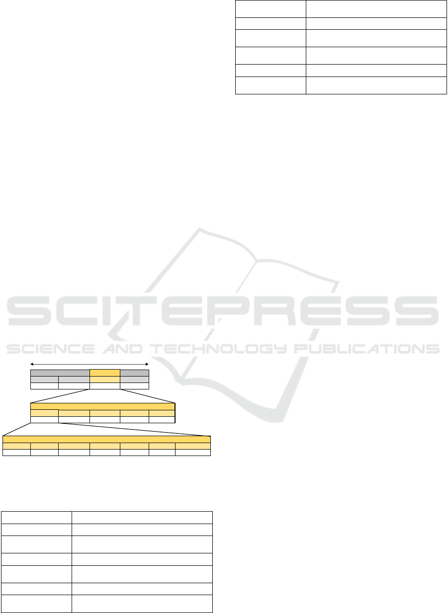
2.4.5 Packet Format
A slim packet structure as shown in Figure 2 is used
to transmit the 3D force sensor data. For test
purposes a 32-bit packet sequence counter value has
been added so receivers may detect if packets have
been lost. This is configurable per software and
disabling reduces the packet length to 15 bytes i.e.
60 us (on air). The content of the packet briefly
described in Table 2.
Figure 2: Packet structure of the proposed WBAN
concept.
Table 2: Elements of the proposed packet structure.
Parameter Description
Preamble 0x55 or 0xAA (depends on first data bit)
Network Address
address of the WBAN (currently
0x4749534E)
CRC CRC-16 polynomial x
16
+ x
12
+ x
5
+ 1
Sequence Number
32-bit TX packet counter (for test purpose
only)
Force Fx, Fy, Fz 3D force vector values (signed)
Node Address
256 nodes can be addresses (within one
WBAN)
Node Error
= 1 if any Data, DAQ or Sensor Error is
present
ACK request = 1 if node requests an acknowledgement
Data Error
= 1 if payload data are invalid (for test
purpose)
DAQ Error
= 1 if the sensor data acquisition unit has
an error
Sensor Error = 1 if the sensor itself has an error
Overload (X, Y, Z)
= 1 if sensor is overloaded in X, Y or Z-
axis
2.4.6 Reliability
When multiple nodes are advertising at short interval
times the medium is heavily utilised and collisions
will happen regularly. Bluetooth LE uses its three
advertising channels in the same order, i.e. 1-2-3 so
packet collisions due to concurrent transmission will
affect all three channels equally which leads to the
loss of data from all concurrently transmitting nodes.
Our concept implements a random channel sequence
where one out of six different channel orders (1-2-3,
1-3-2, 2-1-3, 2-3-1, 3-1-2 or 3-2-1) is randomly
selected prior to advertising. A rudimentary
simulation using Microsoft Excel indicated that a
random channel sequence could outperform a fixed
channel sequence by a factor of 4.
2.4.7 Flexibility
The receivers do not recognise packets with invalid
network address but can be configured to listen on
up to 8 different networks. Multiple logical networks
can be instantiated on the robot for different services
e.g. control related data and ambient information.
Each node in the WBAN is further identified with an
8-bit node address so each logical network can
manage up to 256 nodes.
2.4.8 Security Aspects
The radio device supports 128 bit AES encryption
and authentication features. While authentication is
not implemented in this proof-of-concept it is
supported for later use. We expect encryption, and
especially pairing during authentication will make a
significant addition to the power budget.
3 PROOF OF CONCEPT
3.1 Software Application
The software is organised as an interrupt triggered
state machine. The state diagram of the wireless
sensor nodes in Figure 3 describes a simple
MAC PHY
Preamble NetworkAddr. Payload CRC
1byte 4bytes 12bytes 2bytes
Header Seq.Nr. ForceFx ForceFy ForceFz
2bytes 4bytes 2bytes 2bytes 2bytes
NodeAddr. NodeError ACKrequest DataError DAQError SensorError Overload(X,Y,Z)
8bits 1bit 1bit 1bit 1bit 1bit 3bits
PHY
Payload
Header
19bytes at2Mbps=76us(onair)
roboBAN: A Wireless Body Area Network for Autonomous Robots
53
application that transitions from one state to another,
including a sleep state, in a cyclic fashion.
Figure 3: State diagram of the wireless sensor nodes for
interval-based transmission.
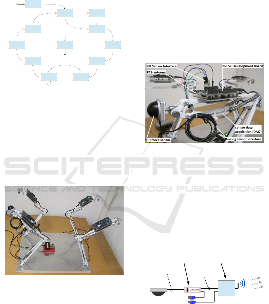
3.2 Demo Setup
3.2.1 Implementation
For the evaluation of the proposed WBAN concept a
test-jig was built to imitate the metallic construction
of the robot’s legs, joints and the solid body
enclosure and so simulate the operating conditions
as close to the target application as possible (see
Figure 4 and Figure 5).
Figure 4: Demo setup of the robot test-jig.
3.2.2 3D Force Sensor
The 3D force sensor was delivered with a separate
data acquisition unit (DAQ) for converting the
analog sensor signals to a digital format, calculating
the force signal and making the data accessible over
SPI. The mounting of this DAQ is shown in Figure
5.
3.2.3 Radio Transmitter (TX)
The brand new nRF52832 was only available as a
pre-release development board (PCA10036) for
engineering purposes. The development board and
the DAQ are powered over the USB interface (see
Figure 6). The orientation of the TX antenna was
considered when mounting the development board
on the robot leg which was mounted such that the
radiation pattern of the antenna is at right angles to
the leg (in Figure 5 the antenna is parallel to the
indicated edge of the PCB).
Figure 5: Flexible leg construction with the 3D force
sensor as foot and the nRF52 development board as
wireless sensor node.
3.2.4 Radio Receiver (RX)
Acting as receivers for the three advertising channels
were three small and lightweight nRF51822 USB
dongles (PCA10000) from Nordic Semiconductors.
These were inserted directly into a USB hub directly
connected to a test computer for data exchange and
voltage supply (see Figure 6.) The dongles listen to
one of the advertising channels each, buffer the
received data to the internal flash and transmit them
to the computer.
Figure 6: Diagram of the wireless sensor node
implementation.
The receiving nRF51 dongles exhibit a radiation
pattern similar to the transmitters, but weaker so, to
avoid cross-polarisation, the same antenna/PCB
orientation is chosen. Mounted on the middle of the
INIT
IDLE
START
RNG
READ
SENSOR
WAIT FOR
SENSOR
PROCESS
DATA
SEND
DATA
PREPARE
SLEEP
SLEEP
WAKE UP
ERROR
Power
OFF
(reset)
peripherals & sensor
initialised
more random
numbers
required
>2 random
numbers
available
RNG
started
sensor
readout
triggered
readout
completed
radio packet
ready
transmission
completed
(advertising < 3)
transmission
triggered
sleep mode
triggered
sleep timer
timeout
context
restored
any unexpected
error
error handling
defined next state
transmission
completed
(advertising = 3)
WAIT FOR
RADIO
Sensor
Node
Analog signals
& sensor supply
Data acquisition
unit at 1 ksps
SPI at
8 Mbps
nRF52832
at 64 MHz
2.4 GHz radio
at 2 Mbps
3D force
sensor
+5V USB supply
ICINCO 2016 - 13th International Conference on Informatics in Control, Automation and Robotics
54
“body” of the robot (Figure 4), the aluminium base
plate of the test jig, they are elevated about 25 mm
from the plate.
3.3 Measurement Results
This sub-section describes measurement results of
experiments conducted using the test-jig.
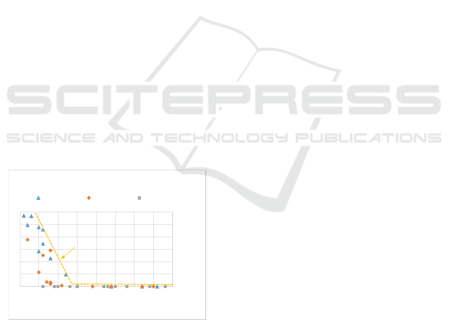
3.3.1 Preliminary Measurement
Before commencing measuremens on the test jig an
indoor line of sight (LoS) measurement was
performed. With one wireless sensor node
transmitting at 0 dBm it could be shown that, up to a
receiver signal of -60 dBm, individual packet error
rates below 0.1 % could be achieved (see Figure 7.)
This figure could be used as an indicator to adjust
the TX power in real-world applications on the robot
so that the receiver signal is stronger than -60 dBm.
3.3.2 3D Force Sensor
An unexpected issue was found in the
implementation of the DAQ. Sensor data is
packaged in 16 bytes with 6 bytes payload and is
clocked out of a ring buffer implemented such that it
is necessary to read the complete ring of 64 bytes.
CPU time and power is subsequently wasted in
finding and extracting the data packet. In addition
the sensor packet was occasionally incompletely
placed in the 64 bytes data block which resulted in a
negative effect on the packet error rate (PER).
Figure 7: Indoor LoS evaluation of RSSI vs. PER
(transmitter at variable distance between 0m and 3m
sending at 0 dBm).
3.3.3 PCB Antennas
First measurements showed that the received signal
at the USB dongles was suspiciously small even
when positioned close to the wireless sensor node
transmitting at 0 dBm. Comparative measurements
with the nRF52 development board and the nRF51
dongles showed that while the RF front-end and
antenna losses of the nRF52 development board (TX
node) was evaluated to be around 7 dB, the nRF51
dongles (RX node) performed approx. 20 dB worse
i.e. losses of 25 dB to 28 dB were measured. The
reason for this is assumed to be the meander
monopole antenna of the small nRF51 dongles
which is small compared to the inverted L PCB
antenna of the nRF52 development board.
3.3.4 Power Consumption of the Wireless
Sensor Node
The power consumption measurements of the
wireless sensor node yielded excellent results which
indicate that power supply from energy harvesting is
viable for the node.
For transmissions at 0 dBm the nRF52832
requires a supply voltage of 3.0 V and consumes 6.9
mA during transmission which results in a TX
power consumption of around 21 mW. The total
energy used during the active state of duration 493
us is approximately 8.6 uJ.
For transmissions at 0 dBm the nRF52832
consumes 5.2 mA during transmission which results
in a TX power consumption of about 16 mW. The
total energy used during the active state of 493 us is
approximately 6.9 uJ.
The random advertising delay affects the
duration of the sleep state but not the active state.
The smallest possible interval times are between
1000 us and 1255 us.
During the shortest sleep state of approx. 500 us
to 760 us around 0.7 uJ to 1.1 uJ is used at an
average power of around 1.4 mW corresponding to
an average current of 0.5 mA at 3.0 V supply (with
DC/DC converter enabled.)
If the DC/DC converter is disabled during the
sleep state the average current drawn from the 3.0 V
supply will increase to 0.7 mA which yields an
average power of around 2.1 mW and therefore an
energy requirement of 1.1 uJ to 1.6 uJ for the same
sleep time.
The unused peripherals on the SoC are
permanently disabled and on entering the sleep state
the CPU is suspended to be woken by a sleep timer
interrupt. The SoC device delivered by the
distributer was a beta engineering sample where the
system OFF mode of the device was not operational
(Nordic, 2015d). With this operational and,
according to the product specification (Nordic
2015c), a power consumption of around 3 uW i.e. 1
0.0
0.5
1.0
1.5
2.0
2.5
3.0
‐70 ‐65 ‐60 ‐55 ‐50 ‐45 ‐40 ‐35 ‐30
PER[%]
RSSI[dBm]
IndoorLineofSightPacketErrorRate
PER[%]atRX1 PER[%]atRX2 PER[%]atRX3
PERborder
roboBAN: A Wireless Body Area Network for Autonomous Robots
55
uA at 3.0 V can be expected including the real time
clock (RTC) to wake-up the device (DC/DC
converter disabled.)
3.3.5 Radio Link Quality
A core quality criterion of the WBAN is the packet
error rate (PER) so some care was taken to evaluate
this. We distinguish between “individual PER,” the
PER of each individual channel and the “overall
PER,” the PER of the individual node. For each
node three individual PERs (each advertising
channel) were measured as well as the four overall
PER values.
The test jig was in an indoor laboratory
environment where many wireless devices in the 2.4
GHz ISM frequency band (WLAN, Bluetooth LE)
were operated in the close vicinity to better show
operation in “real-world” conditions. Several
measurement cycles were performed to establish the
PER at cycle times of 1, 10 and 100 ms and TX
power at 0 dB and -12 dB.
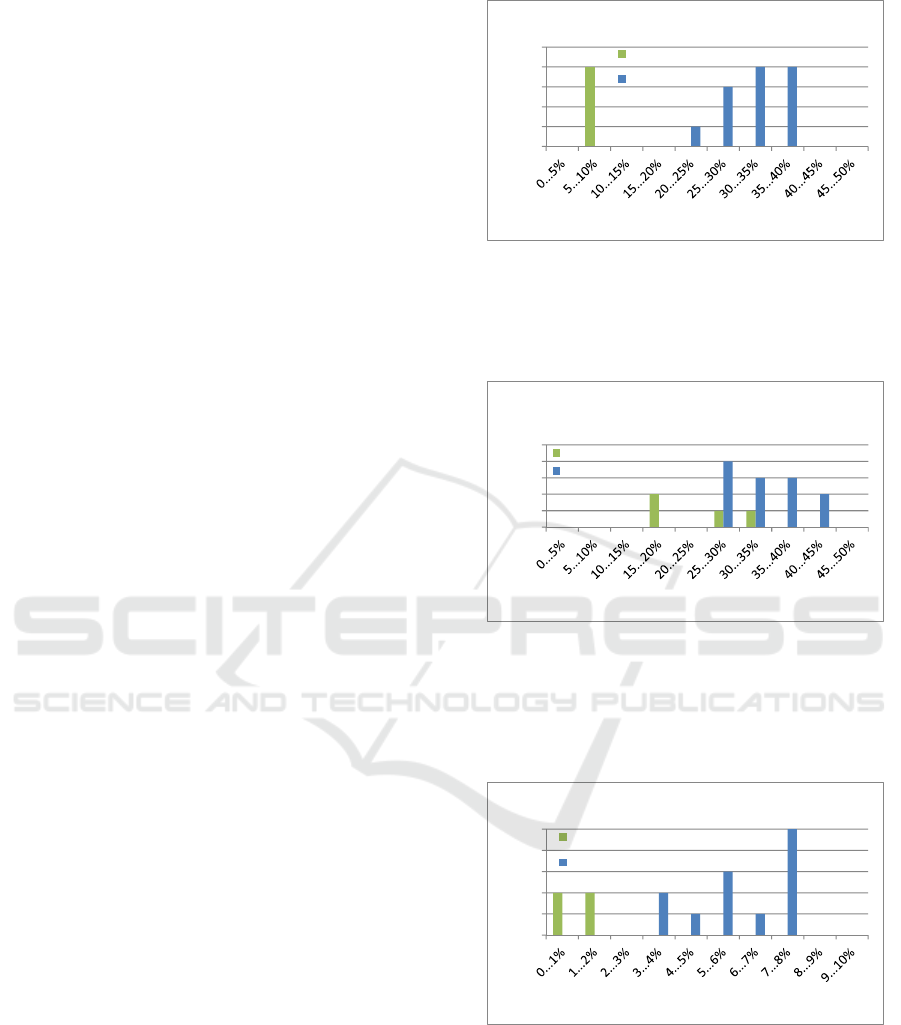
Figure 8 shows the PER for a cycle time of 1 ms.
@ 0 dBm and the random channel sequencer. The
individual PER, at 20% to 40% is quite large, even
considering the ammount of traffic and that the
nodes are not synchronised to each other, but the
overall PER for the sensor nodes is only 5-10%,
largely due to the proposed random channel
sequence.
To cross check the performance of random
channel sequencing the test was repeated with the
exception that the random channel sequencer was
disabled and a fixed channel sequence used instead.
The results are shown in Figure 9. The individual
PER is slightly larger but the overall PER increases
drastically and lies between 15 % and 35 % which is
a direct result of the fact that packets from randomly
synchronised nodes collide on all three channels
with the result that all data is lost. The average value
of the overall PER for fixed channel sequence is
25.6 % compared to 7.3 % for random channel
sequence which is a factor 3.5 higher. This is close
to the factor of arround 4 derived from the
simulation (Section 2.4.6).
The first experiment was repeated with interval
times of 10 ms and 100 ms, the results are shown in
Figure 10 and Figure 11 respectivly where it can be
seen that both the individual and overall PER
decreases substantially with increasing interval time
confirming that packet collisions are less likely to
occur sporadically.
Figure 8: PER evaluation based on 60’000 packets from
four nodes transmitting with 0 dBm at an interval time of
1 ms. Random advertising delay and random channel
sequence are enabled. The “robot” is in standing position
i.e. the legs are not moved.
Figure 9: PER evaluation based on 60’000 packets from
four nodes transmitting with 0 dBm at an interval time of
1 ms. Random advertising delay is enabled but random
channel sequence is disabled (fixed channel sequence is
applied). The “robot” is in standing position. i.e. the legs
are not moved.
Figure 10: PER evaluation based on 60’000 packets from
four nodes transmitting with 0 dBm at an interval time of
10 ms. Random advertising delay and random channel
sequence are enabled. The “robot” is in standing position.
A most interesting effect can be observed when
the four legs of the robot test jig are moved in a
walking pattern. The “walking” robot performs
better than when “standing” which could be
0
1
2
3
4
5
Occurrence[#]
PacketErrorRate[%]
PERat0dBmand1msIntervalTime
OverallPER
IndividualPER
0
1
2
3
4
5
Occurrence[#]
PacketErrorRate[%]
PERat0dBmand1msIntervalTime
(fixedchannelsequence)
OverallPER
IndividualPER
0
1
2
3
4
5
Occurrence[#]
PacketErrorRate[%]
PERat0dBmand10msIntervalTime
OverallPER
IndividualPER
ICINCO 2016 - 13th International Conference on Informatics in Control, Automation and Robotics
56
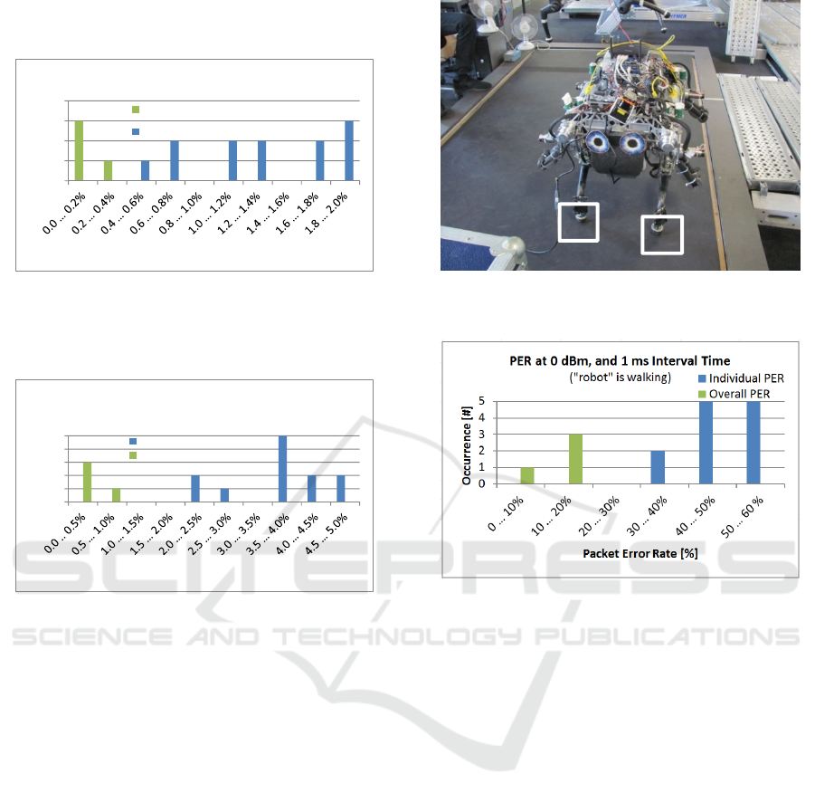
explained with multi-path propagation causing
position dependant channel fading (Figure 12).
Figure 11: PER evaluation based on 60’000 packets from
four nodes transmitting with 0 dBm at an interval time of
100 ms. Random advertising delay and random channel
sequence are enabled. The “robot” is in standing position.
Figure 12: PER evaluation based on 60’000 packets from
four nodes transmitting with 0 dBm at an interval time of
10 ms. Random advertising delay and random channel
sequence are enabled. The “robot” is in walking position
i.e. all four legs are moving with a “walking” pattern.
3.4 Assembly on StarlETH
roboBAN was assembled on the StarlETH, a
transmitter on each foot (Figure 13) whilst the array
of three USB-dongle receivers was mounted on the
bottom of the robot The robot was then made to
walk and two sets of measurements were made, the
first of the PER and the second of the force applied
by the robot leg to the floor.
The PER measurement turned out to be
problematic due to an issue with the Rx dongles.
This had the effect that measurements transmitted to
the PC via a UART->USB converter on the Rx
dongle were corrupted by lost bytes and framing
errors cause by poor buffer handling in the UART.
These additional errors could not be separated from
those occasioned by wireless interference and so
pressured the PER to an unknown amount.
Figure 13: StarlETH with transmitter boards taped to the
feet.
Figure 14: PER evaluation based on packets from four
nodes, mounted on the StarlETH, transmitting with 0 dBm
at an interval time of 10 ms. Random advertising delay
and random channel sequence are enabled. The robot is
walking.
The second set of measurements made was the
force applied on the foot of each robot during the
walking action. The purpose was to confirm the
amount of energy an energy harvester could
potentially capture during the walking activity. The
force applied to each leg was captured via the force
sensor on the foot of each leg and an example is
shown below in Figure 15. The force was not
absolutely measurable, the calibration information
for each of the four sensors is not available, but by
estimating the force and assuming that the sensor
membrane is compressed by 5 mm when the foot
hits the floor, a measure could be arrived at. We
estimate, for this foot, an average of approx. 500 mJ
harvestable energy/step. While we show only one
profile in Figure 15 the profiles of the force applied
to the other feet vary considerably from foot to foot
indicating an imbalance in the distribution of mass
across the robot. The results are only useful as a
general indicator as the robot is currently undergoing
0
1
2
3
4
Occurrence[#]
PacketErrorRate[%]
PERat0dBmand100msIntervalTime
OverallPER
IndividualPER
0
1
2
3
4
5
Occurrence[#]
PacketErrorRate[%]
PERat0dBm,and10msIntervalTime
("robot"iswalking)
IndividualPER
OverallPER
roboBAN: A Wireless Body Area Network for Autonomous Robots
57
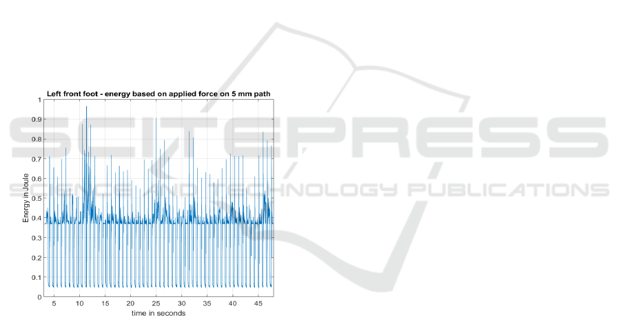
a redesign so a final figure for the harvestable
energy will only be known at a later date.
4 CONCLUDING REMARKS
4.1 Contribution
The focus of this body of work lies on the
conceptual design of a WBAN employing ultra-low
power wireless sensor nodes for use of devices
powered by energy harvesting but mounted on
mobile robots. It has been shown that the application
of the WBAN concept to a robot is feasible. It has
been shown that standardised technologies
conceived for the WBAN market are unsuitable for
this kind of application, especially if high data rate
sensors are to be integrated. It has also been shown
that the sensor interface can be built to ultra-low
power expectations such that power via energy
harvesting is feasible. This means that sensors can
be added to the WBAN without burdening the
robot’s power budget.
Figure 15: Estimated energy harvestable from front left
foot.
The packet size and hence the on-air time, could
be reduced to allow 1 ms sampling rates – a non-
trivial exercise for wireless systems. Using
redundant advertising channels assigned pseudo-
randomly has been shown to be effective in reducing
the packet error rate making our implementation a
superior solution to standard protocols like
Bluetooth LE with which a complete comparison is
given in Table 3.
4.2 Discussion
In this paper a new concept of a wireless body area
network (WBAN) applied to a quadruped robot has
been presented that shows sufficient potential to be
engineered into a working model of the robot. One
of the aims was to reduce the cabling requirements
for the robot. It has been shown that energy
requirements can, with careful engineering, be
reduced as to make energy harvesting a feasible
option and thus the requirement to minimise cabling
can be achieved. Wireless sensors in critical
machine parts are not without their problems. The
packet error rate of 5-10% is high so some work
needs to be done first on optimising the antennas,
the Rx antennas have been shown to be weak, and
for any remaining packet error rate it also needs to
be shown that the motion control loop can handle the
resultant data omission rate. Wireless
communication is notoriously fragile especially in
the face of jamming attacks and further
experimentation needs to establish to what extent the
operation of the WBAN can be maliciously
disrupted.
It might be considered unfortunate that a
standard protocol could not be found for what will
ultimately become a common issue, the interfacing
of third party data and information providers to a
mobile robot. A comparison of the proven design,
shown in Table 3, with Bluetooth LE shows that this
technology will simply never fulfil the requirements
that a robot WBAN poses so specification work is
required to ensure some form of interoperability
between application data providers and the robots.
The on-time of a sensor is just under 500 us, the on-
air time of its packet is just under 80 us which, at 1
ms sample time allows a theoretical maximum of 12
nodes, assuming no collisions, so while the practical
limits of high data rate nodes are close to being
reached there is ample space for a number of low-
data rate nodes, even those using ACKs, to ensure
transmissions are successful.
Estimates show that the weight of the robot is
sufficient to provide an energy source for powering
the wireless transmissions.
4.3 Outlook
Since it has been shown to be feasible that the
movement of the robot will generate enough
harvestable energy to power the connection to the
WBAN, the development of a suitable harvester and
force sensor would be appropriate next steps. Whilst
the half-sphere construction of the currently used
sensor allows some detection of micro-terrain
features one could speculate that a sensor based on
the features of a dogs paw might be more
ICINCO 2016 - 13th International Conference on Informatics in Control, Automation and Robotics
58

appropriate. Secondly a combined sensor/harvester,
that is a harvester whose harvested energy levels
also indicate the force applied, would be of
particular interest for this kind of application.
ACKNOWLEDGEMENTS
We are thankful to Erich Ruff and Tiziano Fabbroni,
both of InES, for their support. Further thanks go to
Mark Hoepflinger and Marco Hutter of the
Autonomous System Lab (ASL) of ETH Zürich for
the access to the StarlETH and to Ákos Tar and
Szabi Fekete from Opto Force for their helpful
discussions.
REFERENCES
ASL, 2015, Autonomous Systems Lab, “Multi-Purpose
Legged Transporter,” StarlETH fact sheet, November
2015.
BSIG, 2015, Bluetooth special interest group (SIG),
Specification adopted documents, “Bluetooth Core
Specification 4.2,” 2015, [Online]. Available:
https://www.bluetooth.org/en-us/specification/adopted
-specifications [Accessed: November 12, 2015]
Bynam, K. Hong, Y.J. Nair, J. Thejaswi, C. Jos, S. Park,
C. et al., 2013,“Samsung’s Physical Layer Proposal,”
Proposal as response to IEEE TG4q call for
proposals, November 2013.
Chen, M. Gonzalez, S. Vasilakos, A. Cao, H. Leung,
V.C.M. 2011 „Body area networks: A survey,” Mobile
Networks and Applications, vol. 16, no. 2, pp. 171-
193, April 2011.
CHERRY switches, 2015, “Wireless Switches -
Generator,” AFIG and AFIM Series data sheet, April
2015.
Devita, G. Wong, A.C.W. Dawkins, M. Glaros, K. Kiani,
U. Lauria, F. et al., 2014 “A 5mW multi-standard
Bluetooth LE/IEEE 802.15.6 SoC for WBAN
applications,” European Solid State Circuits
Conference (ESSCIRC), ESSCIRC 2014 - 40th, pp.
283-286, September 2014.
Dynastream Innovations, 2014, “ANT USB dongle”,
ANTUSB-m Stick data sheet, rev. 1.7, July 2014.
H. Cao, V. Leung, C. Chow and H. Chan, 2009, “Enabling
technologies for wireless body area networks: A
survey and outlook,” IEEE Communications
Magazine, vol. 47, no. 12, pp. 84-93, December 2009.
Hutter, M. Gehring, C. Bloesch, M. Hoepflinger, M.A.
Remy C.D. Siegwart, R. 2012, “StarlETH: A
compliant quadrupedal robot for fast, efficient, and
versatile locomotion,” Proceedings of the
International Conference on Climbing and Walking
Robots (CLAWAR) 2012 - 15th, pp. 1-8, April 2012.
IEEE, 2005, “Local and metropolitan area networks – Part
15.1: Wireless medium access control (MAC) and
physical layer (PHY) specifications for wireless
personal area networks (WPANs),” IEEE Standard
802.15.1, June 2005.
IEEE, 2011, IEEE 802.15 Task Group 6, 2015, “IEEE
802.15 WPAN Task Group 6 (TG6) - Body Area
Networks,” rev. 0.4, June 2011, [Online]. Available:
http://www.ieee802.org/15/pub/TG6.html [Accessed:
April 24, 2015]
IEEE, 2012, “Local and metropolitan area networks - Part
15.6: Wireless Body Area Networks,” IEEE Standard
802.15.6, February 2012.
IEEE, 2013, IEEE 802.15 Task Group 15.4q, “IEEE
802.15 WPAN Ultra Low Power Task Group 15.4q
Ultra Low Power (ULP),” 2013, [Online]. Available:
http://www.ieee802.org/15/pub/TG4q.html [Accessed:
November 12, 2015]
Insteon, 2005 “Insteon: The details”, Insteon white paper,
rev. 2, 2005.
Microsemi, 2013, “Ultra-Low-Power RF Sub-GHz
Transceiver (779 to 965 MHz),” ZL70251 data sheet,
rev. 2, October 2013.
Movassaghi, S. Abolhasan, M. Lipman, J. Smith D.
Jamalipour, A. 2014, “Wireless body area networks: A
survey,” IEEE Communications Surveys & Tutorials
,
vol. 16, no. 3, pp. 1658-1686, August 2014.
Nordic Semiconductors, 2015a, info center, “Enhanced
shockburst user guide,” 2015, [Online]. Available:
http://infocenter.nordicsemi.com/index.jsp?topic=%2F
com.nordic.infocenter.sdk51.v10.0.0%2Fesb_users_gu
ide.html&cp=4_1_0_5_2 [Accessed: November 12,
2015]
Nordic Semiconductors, 2015b, info center, “Gazell link
layer user guide,” 2015, [Online]. Available:
http://infocenter.nordicsemi.com/index.jsp?topic=%2F
com.nordic.infocenter.sdk51.v10.0.0%2Fgzll_02_user
_guide.html&cp=4_1_0_5_0 [Accessed: November
12, 2015]
Nordic Semiconductors, 2015c, “nRF52832 product
page,” 2015, [Online]. Available: https://www.nordic
semi.com/eng/Products/Bluetooth-Smart-Bluetooth-
low-energy/nRF52832 [Accessed: November 13,
2015]
Nordic Semiconductors, 2015d, “nRF52832 Errata v1.1”,
nRF52832 errata, rev. 1.1, November 2015.
Opto Force, 2015, “3D force sensor (OMD),” 2015,
[Online]. Available: http://optoforce.com/3dsensor
[Accessed: November 16, 2015]
Raemy, N. Pengg, F.-X. Scolari, N. Vouilloz, A. 2014,
“icyTRX-65, a 2.4 GHz Silicon RF IP Optimized for
Low-power Bluetooth Low Energy,” CSEM Scientific
and Technical Report 2014, p. 127, 2014.
Sigma Designs, 2013, “General Purpose Z-Wave SoC,”
SD3502 data sheet, rev. PMB12376, December 2013.
Texas Instruments, 2013, “2.4 GHz IEEE 802.15.4 /
ZigBee-ready RF Transceiver,” CC2420 data sheet,
rev. SWRS041c, February 2013.
Ullah, S. Higgins, H. Braem, B. Latre, B. Blondia, C.
Moerman I. et al., 2010, “A comprehensive survey of
wireless body area networks,” Journal of Medical
Systems, vol. 36, no. 3, pp. 1065-1094, August 2010.
roboBAN: A Wireless Body Area Network for Autonomous Robots
59
APPENDIX
Table 3: Comparison of Bluetooth Low Energy and the Proposed WBAN Concept.
Parameter Bluetooth Low Energy Proposed Method
Frequency band 2.4 GHz (ISM) 2.4 GHz (ISM)
Number of advertising channels 3 3
Frequency of advertising channels 2’402 , 2’426 , 2’480 MHz 2’407 , 2’422 , 2’474 MHz
Sequence of advertising channels Fixed (1 – 2 – 3) Random (6 possible combinations)
Minimum advertising interval 20 ms 1 ms
Random advertising delay 0 … 10 ms 0 … 255 us
On air data rate 2 Mbps 2 Mbps
Packet duration (10 byte payload) 160 us 64 us
Packet reception at receiver Successively scanning channels Parallel scanning of all channels
Packet acknowledgement Yes (optional)
Table 4: Comparison of discussed wireless protocols operating in the 2.4 ghz ISM frequency band.
Parameter Unit
IEEE 802.15.4
(w/o ZigBee)
Bluetooth
Low Energy
IEEE 802.15.6
Narrow Band
Proprietary
Nordic ESB
Proprietary
Nordic SB
Frequency Band MHz 2’400 (ISM) 2’400 (ISM) 2‘400 (ISM) 2’400 (ISM) 2’400 (ISM)
Modulation - O-QPSK GFSK π/4-DQPSK GFSK GFSK
Spreading Sequence - DSSS A-FHSS 1 non non
Gross data rate kbps 2000 1000 600 2000 2000
Information data rate kbps 250 1000 971.4 2000 2000
Maximum payload Byte 118 36 255 32 32
Packet payload Byte 10 (budgeted for packet size calculation)
Packet size Byte 25 20 34.125 17.125 16
Packet duration us 800 160 281 68.5 64
Min. cycle time
(no ACK)
ms
1.4
20…30 unknown
0.2 0.2
Min. cycle time
(with ACK)
ms
2.2
20…30 unknown
0.4
unknown
Error detection - FCS CRC FCS CRC CRC
Error correction - Yes No Yes No No
Radio device availability - good good poor good good
ICINCO 2016 - 13th International Conference on Informatics in Control, Automation and Robotics
60
