
Researching Attitude-control Algorithm of Ejection Seats
based on Time-sharing Strategy
Minghuan Zhang
1
, Ming Wu
2
, Yu Su
1
and Cheng Zhang
1
1
School of Astronautics, Northwestern Polytechnical University, Xi’an, China
2
Aerospace Life-Support Industries, LTD, Xiangyang, China
Keywords: Ejection Seats, Attitude-control, Time-sharing Control, Minimum Safe Altitude, Optimization, Simulation.
Abstract: An attitude-control algorithm for ejection seats on “H” shaped motor is presented in this paper. The control
algorithm is based on time-sharing strategy, and the parameters in algorithm are optimized by using PSO
method. Through simulating under Matlab/Simulink in different ejection conditions, the infection of time-
sharing strategy in attitude-control is analyzed, and the minimum safe altitude is compared with K36D-
3.5A, ACES II and 120 ejection conditions in GJB 1800A-2007. The simulation results and analysis show
that this control algorithm on “H” shaped motor can improve escape performance at low-altitude and
adverse-attitude, thus proving the algorithm in this paper to be reliable and effective.
1 INTRODUCTION
Ejection seat is a key lifesaving appliance of modern
fighter in emergency (Wang, 2014), and its core
technology is attitude and trajectory control of the
seat after ejection. Most of ejection seats in service
at present are under the 3
rd
generation escape
system. To improve the pilot’s rescue, sequential
control technology (used in the 3
rd
generation) is
applied to make the seat for increasing the ejection
altitude (Miles, 2015 and Wang, 2014). Along with
high-tech of weapon, complexity of battlefield and
quicken of combat rhythm, pilot would be highly
possible to escape under low-altitude, adverse-
attitude conditions or at extremely high speed.
Therefore, it is imperative to achieve adaptive
control of ejection attitude. The 4
th
generation of
ejection seat is designed to solve the rescue problem
in low-altitude and adverse-attitude conditions
beyond the current generation, and its core is the
application of thrust vector continuous control
technology (Ma,2000 and Keller, 2008). By the fast
switching among thrust vector, the seat can gain
maximal lift as quick as possible. Thereby, the
safety is increased.
Technology on the 4
th
generation escape system
was start to study from 1970s, however, it has not
implemented for engineering application nowadays.
One of the main technical bottlenecks is the
application of thrust vector continuous control. U.S.
Air Force Research Lab proposed the structure of
the ejection seat under the 4
th
generation escape
system (Blairnald, 1998). The “H” shaped motor
installed on the seat so that the nozzles located at
four corners can obtain large moment arms for
attitude-control. It makes maintaining a constant
pressure become possible. (Feng, 2007) present a
safe altitude impact factor method under the 3
rd
generation. It analyzed infection of aircraft
parameters start from ejection to safe altitude.
Despite this work can improved escape performance
at medium-low-speed and lower-altitude somehow,
it only meet 44% of the minimum safe altitude in
GJB 1800-93. (Yuan, 2009) presents a nonlinear
inverse-dynamics method to design the control law
of the ejection seat under the 3
rd
generation. Results
under medium-low speed can be verified in 4
th
generation escape system, but the robustness of this
method need to be improved. Both of above two
methods are based on sequential control technology.
It can’t meet the requirement of the adaptive control
which is the symbol of the 4
th
generation.
We present a time-sharing attitude-control
algorithm based on thrust vector continuous control
technology. The parameters of controller is
optimized by Particle Swarm Optimization(PSO).
The experimental results and analysis show that this
algorithm can achieve fast robust attitude-control of
ejection seat. Moreoever, this strategy gives a new
262
Zhang, M., Wu, M., Su, Y. and Zhang, C.
Researching Attitude-control Algorithm of Ejection Seats based on Time-sharing Strategy.
DOI: 10.5220/0005975702620267
In Proceedings of the 13th International Conference on Informatics in Control, Automation and Robotics (ICINCO 2016) - Volume 2, pages 262-267
ISBN: 978-989-758-198-4
Copyright
c
2016 by SCITEPRESS – Science and Technology Publications, Lda. All rights reserved
solution of adaptive control under 4
th
generation
system.
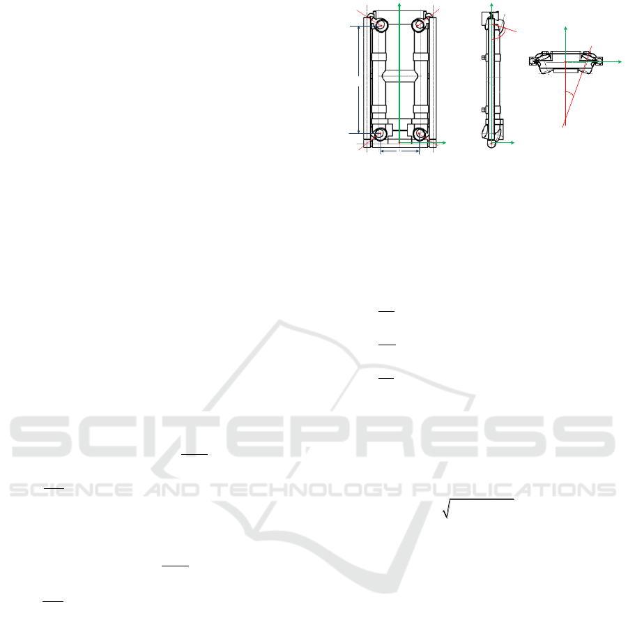
2 MATHEMATICAL MODEL OF
“H” SHAPED MOTOR
Fig.1 shows the “H” shaped motor installs at the
ejection seat back. The motor is equipped with four
fixed nozzle, which provide thrust for the ejection
seat. Under body axis system, the thrust of each
nozzle is shown as Eq.1 and Eq.2.
1,2,3,4i
refer to
the nozzle number as the Fig.1 shows.
11
1
11
sin cos
cos
( 1) sin sin
1,2
hix hi h h
hiy hi h
i
hiz hi h h
FF
FF
FF
i
(1)
22
2
22
sin cos
cos
( 1) sin sin
3,4
hix hi h h
hiy hi h
i
hiz hi h h
FF
FF
FF
i
(2)
And the moment of each can be describe as Eq.3
and Eq.4.
1
hix 1 1 h1 1 2
1 1 1 h2 1 1
1 1 1 1 1
( 1)
M ( 1) sin sin (L ) cos
2
( 1)
M sin cos L ( 1) sin sin
2
M sin cos ( ) cos
1,2
i
i
hi h h c hi h h
i
i
h y hi h h hi h h c
h z hi h h h c hi h c
F y F L
F F x
F L y F x
i
(3)
1
1
hix 2 2 2 2
2 2 h2 2 2
2 2 2
( 1)
M ( 1) sin sin cos
2
( 1)
M sin cos L ( 1) sin sin
2
M sin cos cos
3,4
i
i
hi h h c hi h h
i
i
hiy hi h h hi h h c
hiz hi h h c hi h c
F y F L
F F x
F y F x
i
(4)
Nozzle #1 and nozzle #2 have the same
installation angle direction, while nozzle #3 and
nozzle #4 have the same installation angle direction.
hi
and
hi
are shown in the Fig.1 b) and c), in which
i
refers to the nozzle number.
When all four nozzles work at the same time, the
total thrust and moment is shown as Eq.5 and Eq.6:
1 2 3 4
1 2 3 4
1 2 3 4
hx h x h x h x h x
hy h y h y h y h y
hz h z h z h z h z
F F F F F
F F F F F
F F F F F
(5)
c
O
cc
OZ
cc
OY
1h
L
2h
L
Nozzle #1 Nozzle #2
Nozzle #3 Nozzle #4
c
O
cc
OX
h
cc
OX
cc
OZ
c
O
h
a)Front View b)Side View c)Upper View
cc
OY
Figure 1: The structure of “H” shaped motor under body
axis system.
1 2 3 4
1 2 3 4
1 2 3 4
hx h x h x h x h x
hy h y h y h y h y
hz h z h z h z h z
M M M M M
M M M M M
M M M M M
(6)
The motion attitude equations of ejection seat are:
sin cos
( cos sin ) / cos
( cos sin )
yt zt
yt zt
xt yt zt
d
dt
d
dt
d
tg
dt
(7)
In above,
,,
refers to pitch, yaw and roll angle;
,,
xt yt zt
are palstances around three axes under
body axis system.
Attack and sideslip angle of ejection seat are
,
;
,,
xt yt zt
V V V
is three velocity components of
c
V
:
2 2 2
( / )
arcsin( / )
c xt yt zt
yt xt
zt c
V V V V
arctg V V
VV
(8)
3 ATTITUDE-CONTROL
ALGORITHM
To maintain internal pressure balance, “H” shaped
motor takes the control mode that each two nozzles
has dual thrust vector. Once installation angle
direction is set, it will not change through the all
procedure. Thus, interconnection of each attitude
angle between control moments is bad for the
control algorithm design. We take the time-sharing
control strategy. By optimizing installation angle
direction of each nozzle, we can achieve decoupling
of attitude-control moment.
3.1 Time-Sharing Control Algorithm
In time-sharing control strategy, “H” shaped motor
Researching Attitude-control Algorithm of Ejection Seats based on Time-sharing Strategy
263

has three modes (pitch, yaw and roll mode). The
thrust and moment of each is shown as Eq.9, Eq.10
and Eq.11.
Pitch mode:
1 2 3 4
(1 )
,
22
0
h h h h h h
xy
KK
F F F F F F
MM
(9)
Yaw mode:
1 3 2 4
(1 )
,
22
0
h h h h h h
xz
KK
F F F F F F
MM
(10)
Roll mode:
1 4 2 3
(1 )
,
22
0
h h h h h h
yz
KK
F F F F F F
MM
(11)
h
F
is the total thrust of the “H” shape motor, which is
a constant value.
K
is the coefficient of each nozzle
in dual control mode. The trust of four nozzle is
determined totally by
h
F
and
K
.
We establish the inconsistent equations set on
Eq.6 and three control modes. And optimize the
installation angle of nozzles by finding optimal
solution of this set. This is also the procedure of
decoupling the control moment of three channels
(Pitch, Yaw and Roll). Due to the specialization of
inconsistent equations, coupling moments in three
control mode can be zero at the same time. But the
process of finding optimization ensures that residual
coupling moment is far miner than the main control
moment. Therefore, the residual coupling moment
can be taken as small perturbation.
3.2 Algorithm Design
Under the time-sharing control strategy, the time of
each channel is limited. The attitude-control is
further weakened by constraint of ejection altitude.
If control time is mainly spent on decoupling of
palstances, attitude-control period could be delayed.
If ignore the decoupling and concentrate on attitude-
control, the speed of attitude-control will be slow,
and even influence the stability of the system.
Finally, trajectory control will be affected.
To minimize the motion decoupling, we take a
switching strategy between coupling palstances and
attitude to achieve fast control of attitude.
3.2.1 Control Objective
Set
( , , , , , )
(refers to pitch, yaw, roll, pitch
palstance, yaw palstance and roll palstance) as
control variables, and its expectation is signed as
* * * * * *
( , , , , , )
. To maintain the stability of
system,
0/s
; To ensure that the seat
can get the maximum lift, the expectation of roll
is
*
0
and yaw is
0
by adjustment of
*
.
According to finding the optimization of
inconsistent equations, installation angle direction
of nozzle after decoupling is
12
40 , 58 ,
hh
12
72.5 , 7
hh
. When the pitch expectation is
*
38
, the lift can be maximum, and expectation
of control variable is :
* * * * * *
( , , , , , ) (38 ,0 ,0 ,0 / ,0 / ,0 / )sss
3.2.2 Transfer Function
To design the control system, the transfer function
between
K
and control variable:
3 3 4
2
42
3
2
42
3 3 4
2
42
3
()
()
()
()
()
()
()
()
s a s a a
K s s a s a
sb
K s s b s b
s b s b b
K s s b s b
sc
K s s
(12)
In above,
22
,ab
is static stability of related control
channel.
3 3 3
,,a b c
is the efficiency coefficient, which
refers to palstance increment of related control
channel when
K
increase.
44
,ab
is the palstance
increment of trajectory tangent line.
3.2.3 Linear Systems Control Design
Take pitch control channel as example, the system
block diagram is shown as Fig.2.
e
is the difference
of pitch expectation and actual value;
,,
P I D
K K K
refers to gain of proportion, integration
and differentiation in PID algorithm;
K
( thrust
partition coefficient of nozzles in pitch channel) can
be calculated by
,,
P I D
K K K
and current
e
.
In order to maintain the dynamic performance of
this control system,
,,
P I D
K K K
can be optimized
through PSO method.
e
P
K
I
K
s
D
Ks
k
()s
k
1
s
*
Figure 2: Control block diagram of pitch channel.
ICINCO 2016 - 13th International Conference on Informatics in Control, Automation and Robotics
264
Velocity and position of particle in search space
can be described as:
1 1 1 2 2
11
( ) ( )
t t t t t t
t t t
v wv c r P a c r G a
a a v
(13)
In which,
a
is the particle position and
v
is velocity.
w
is inertia factor and
12
,cc
are acceleration
constants.
12
,rr
are random values between [0,1].
[ , , ]
t P I D
P K K K
is the optimal control parameter of
particle so far and
[ , , ]
t P I D
G K K K
is the whole
Particle Swarm’s best parameter so far.
The optimization flow chat of PSO algorithm in
pitch channel shows as follows:
Step 1 Initialize all the particle’s position and
velocity in swarm, and set optimum
control parameters
t
P
and
t
G
;
Step 2 Check whether the adaptive factor of
every particle is better than optimum
control parameter
t
P
, if yes, update the
t
P
to current particle adaptive factor;
Step 3 Check whether the adaptive factor of
every particle is better than optimum
control parameter
t
G
, if yes, update the
t
G
to current particle adaptive factor;
Step 4 Update particle’s position and velocity
use Eq.13;
Step 5 If the iterative step meet the max value
or the particle adaptive factor smaller
than lower limit, exit and get optimum
value. Otherwise, return to Step 2.
The parameters in PSO algorithm are as follows:
Inertia factor is
0.6w
;
Acceleration constants are
12
2cc
;
Iteration number is 100;
Particle number is 100;
Minimum particle adaptive factor is 0.1.
K
of each channel can be obtained:
1 1 1
2 2 2
3 3 3
4 4 4
5 5 5
6 6 6
P I D
P I D
P I D
P I D
P I D
P I D
de
K e K e dt K pitch
dt
de
K e K e dt K yaw
dt
de
K e K e dt K roll
dt
K
d
K K dt K pitch
dt
d
K K dt K ya
palstance
palstaw
dt
d
K K dt K roll
dt
nce
palstance
(14)
According to PSO results, gains of each control
channel are shown as Eq.15 and Fig.3.
1 2 3 4 5 6
1
2 3 4 5 6
1 2 3 4 5 6
6, 3
0.5 180 70
0.9 70 10
0.8 10 80
0.5 80 180
0, 10
0.8, 0.5, 0
P P P P P P
I
I I I I I
D D D D D D
K K K K K K
K
K K K K K
K K K K K K
(15)
3.2.4 Switching Control Strategy
Our switching control strategy of coupling
palstances and attitude is illustrated as Fig.4.
4 SIMULATION RESULTS AND
ITS ANALYSIS
Based on 120 ejection conditions which is regulated
by GJB 1800-2007 (General Specification for
Ejection Seat Type of Aircrew Emergency Escape
System), we experiment under Matlab/Simulink
simulation environment. And we verify the
performance of attitude-control algorithm by
minimum safe altitude and changing curve of
attitude angle after ejection.
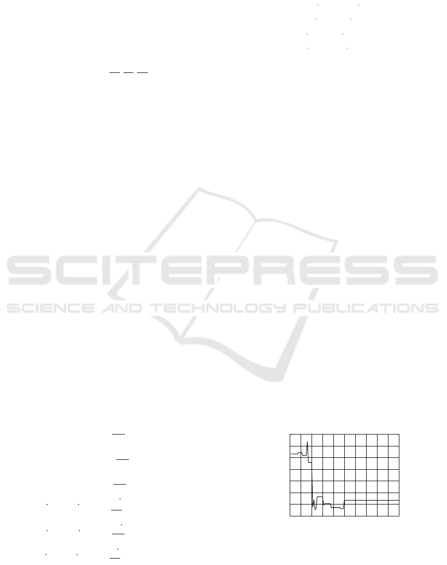
We display simulation results under four type
conditions. The simulation time is 1.8s and the
simulation step is 0.001s. Fig.5 shows the changing
curves of attitude angle after ejection.
It is noted that all the angle and velocity here
refers to the angle and velocity of aircraft under
inertial frame. As simulation results, curves in red is
pitch, curves in blue is roll and curves in green is
roll.
Fig.5 a) and b) shows the simulation results of
large roll angle attitude.
0 10 20 30 40 50 60 70 80 90 100
0
0.5
1
1.5
2
2.5
3
3.5
Iteration Number
Gain
Figure 3: The optimization curve of PSO.
Researching Attitude-control Algorithm of Ejection Seats based on Time-sharing Strategy
265

abs(W_y)>200°/s
Yaw Palstance
Control
Theta>75° abs(Wx)>200°/s
Roll Palstance
Control
Pitch Control
abs(Gama)>160°且
Theta<30°
abs(Wx)>200°/s
Pitch Control
abs(Gama)>20° or
abs(W_x)>100°/s
abs(Wz)>100°/s
Pitch Palstance
Control
Roll Control
Pitch Control
Current State
6-DoF Model
Y
Y
Y
Y
Y
Y
Y
N
N
N
N
N
N
N
Roll Palstance
Control
Figure 4: Switching control strategy.
0 0.2 0.4 0.6 0.8 1 1.2 1.4 1.6 1.8
-200
-150
-100
-50
0
50
100
150
200
t(s)
Attitude Angle(°)
0 0.2 0.4 0.6 0.8 1 1.2 1.4 1.6 1.8
-40
-30
-20
-10
0
10
20
30
40
50
t(s)
Attitude Angle(°)
0 0.2 0.4 0.6 0.8 1 1.2 1.4 1.6 1.8
-80
-60
-40
-20
0
20
40
60
t(s)
Attitude Angle(°)
0 0.2 0.4 0.6 0.8 1 1.2 1.4 1.6 1.8
-200
-150
-100
-50
0
50
100
150
200
t(s)
Attitude Angle(°)
a)Large roll angle attitude:
velocity 0km/h, dive angle 0
0
,
sink-rate 0m/s, roll angle 180
0
b)Large roll angle attitude:
velocity 250km/h, dive angle 0
0
,
sink-rate 50m/s, roll angle 180
0
c)Large dive angle attitude:
velocity 0km/h, dive angle 60
0
,
sink-rate 0m/s, roll angle 0
0
d)Large dive angle attitude:
velocity 450km/h, dive angle 90
0
,
sink-rate 0m/s, roll angle 0
0
Attitude angle(
0
)
Attitude angle(
0
)
Attitude angle(
0
)
Attitude angle(
0
)
t(s) t(s) t(s) t(s)
Figure 5: Curves of attitude angle in adverse conditions.
Due to the time-sharing strategy, the system is in
pitch control channel from 0-0.35s in Fig.5 a). Since
the initial aerodynamic-force is too low to take into
consideration, the roll angle has not changed in this
period; The roll angle is close to the control target
38°around 0.35s, so we switch the system to roll
control channel. During the period of 0.35-1.2s the
system is under roll control channel, pitch angle has
drifted in some extend due to the increase of
aerodynamic-force and infection of coupling
palstances. The system enters stability augmentation
control condition after 1.2s; Roll and pitch angle are
around the control target during 1.2-1.8s. In the
whole process, the velocity of ejection seat is quite
small, therefore the infection of aerodynamic
moment from sideslip-angle is not big and the
control period is quite short.
Similarly in Fig.5 b), during the time period 0-
0.4s and 0.4-1s, roll angle control and pitch angle
control has been affected due to the switching
strategy. In addition, the pitch and roll channel
realize fast attitude stable.
Fig.5 c) and d) shows the simulation results of
large dive angle attitude. The system can achieve
fast stable of pitch attitude within 0.5s. Because “H”
shaped motor has symmetric control moment in
pitch channel and coupling moment of roll and yaw
is negligible, the change of roll and sideslip-angle is
too small to affect dynamic performance of the
system.
From simulation results, this time-sharing
strategy can achieve fast, effective and stable control
of ejection seat attitude.
We compare our results with the minimum safe
altitude requirement of ACES II, K36D-3.5A in
adverse conditions (Barnette, 1998) in Tab.1. The
minimum safe altitude is
12
min(0, )h h h
,
1
h
is the
altitude when ejection and
2
h
is the lowest altitude of
movement curve.
ICINCO 2016 - 13th International Conference on Informatics in Control, Automation and Robotics
266
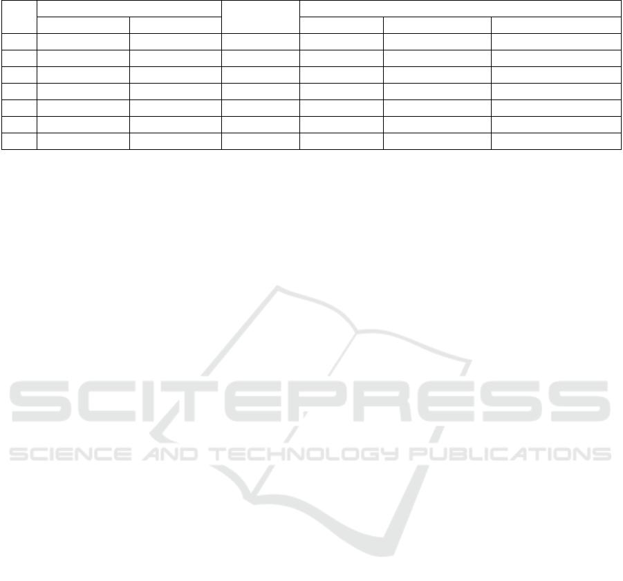
Table 1: Comparison of minimum safe altitude.
No.
Aircraft Attitude
Velocity
(KEAS)
Minimum Safe Altitude(ft)
Dive Angle(
0
)
Roll Angle(
0
)
ACES II
K36D-3.5A
Our Results
1
0
60
120
0
0
0
2
0
180
150
150
96
91
3
0
1
0
150
116
137
66
4
60
0
200
335
288
259
5
30
0
450
497
518
454
6
60
60
200
361
299
331
7
45
180
250
467
323
353
Notes: 1. The current sink-rate of aircraft is 10,000ft/min;
2. KEAS (Knots Equivalent Air Speed) is 1knot=1.85km/h.
In the first 5 states in Tab.1, our minimum safe
altitudes are all lower than that in ACES II and
K36D-3.5A; And the following two are better than
ACES II.
GJB 1800-2007 regulates 120 conditions, 88 of
which is low speed and 32 is high speed. By
experimental comparison, our algorithm can meet
the 67 conditions in low speed, about 76%. In high
speed, 24 conditions can meet the requirement,
about 75%. Based on ejection seat with “H” shape
motor, our algorithm can effectively increase the
ejection altitude and therefore improve the
occupant’s rescue.
5 CONCLUSIONS
This paper proposes an attitude-control algorithm for
ejection seats based on time-sharing control strategy.
The parameters of controller are optimized by
applying PSO method. Simulation results show that
our algorithm can meet the requirement of 75%
conditions in GJB 1800-2007, which included low-
altitude, adverse-attitude and some of the high speed
conditions. Based on continuous thrust vector
control framework, our approach is designed totally
under 4th generation escape system. Experiment and
its analysis verify that our approach can feasibly and
effectively achieve adaptive control.
ACKNOWLEDGEMENTS
This work is supported by the National Natural
Science Foundation of China (No.61502391), the
China Space Foundation (No.N2015KC0121).
REFERENCES
Wang, Y., F., Han, L., L., Wang, F., 2014. Review of
Ejection Seat Electronic Program Controller. Applied
Mechanics and Materials, 551: 530-534.
Miles, J, E., 2015. Factors Associated with Delayed
Ejection in Mishaps Between 1993 and 2013.
Aerospace Medicine and Human Performance, 86(8):
774-781.
Wang, Y., F., Chen, G., Han, L., L., 2014. The
Comprehensive Survey for the Numerical Simulation
of the 4th Generation Rocket Ejection Seat Thrust
Vector Control System. Design, Manufacturing and
Mechatronics, 551: 523-529.
Ma, D., Obergefell, L., Rizer, A., et al, 2000. Biodynamic
Modeling and Simulation of the Ejection
Seat/Occupant System. Biodynamic Modeling &
Simulation of the Ejection Seat/occupant System.
Keller, K., Plaga, J,. 2008. The Ejection Seat Test
Database: A Resource for Enabling Aircrew Safety
and Survivability. AIR FORCE RESEARCH LAB
WRIGHT-PATTERSON AFB OH BIOMECHANICS
BRANCH.
Blairnald, A., 1998. 4TH Generation Escape System
Technologies Demonstration Phase II. Generation
Escape System Technologies Demonstration Phase II.
Feng, W., C., Lin, G., P., 2007. Multi-parameter and
Multi-mode Control Simulation Analyses of Ejection
Seat. Journal of System Simulation, 19(10): 2283-
2286.
Yuan, W., M., 2009. Research on Attitude-Control Project
of the Ejection Seats. Nanjing
:
Nanjing University of
Aeronautics and Astronautics.
Barnette, B., Peterson, K., L., 1998. MAXPAC Update
and Lessons Learned. Proceeding of the 36th Annual
SAFE Symposium, America: SAFE Association.
Researching Attitude-control Algorithm of Ejection Seats based on Time-sharing Strategy
267
