
Multilink Micro Robots Designed for Inspection in Pipes of Small
Diameters
M. M. Knyazkov, E. A. Semenov, A. N. Sukhanov and A. A. Kryukova
Institute for Problems in Mechanics of the Russian Academy of Sciences,
Prospect Vernadskogo 101-1, Moscow, The Russian Federation
Keywords: Micro Robots, Pipeline Inspection, Mechatronic Design, Friction.
Abstract: The importance of designing robotic platforms for pipes of small diameters inspection is connected with
necessity of efficiency improvement in technical diagnostics of pipelines of different use, especially in
mechanical engineering. This paper is devoted to in-pipe micro robot design. Different techniques of the
robot’s motion inside a pipeline have been discussed. The proposed design of the in-pipe robot may be used
in experimental investigation of different inspection techniques. The method of determining the speed of
micro robot allows finding the speed of micro robot when it moves in different environments with different
viscosity under the absence and presence of excessive pressure in the piping system.
1 INTRODUCTION
Research and development of miniature robots for
movement in pipes is actively conducted in the UK,
Sweden, Italy, Germany, USA, Arab Emirates,
China and Japan. Robotics operations for inspection
and repair of pipelines are based on international and
national R&D programs.
There are many papers devoted to R&D of
miniature robots and control systems for them
(Valdastri et al., 2009; Becker et al., 2010). We
apply our design for pipes of small diameters (4-
10mm) only. The importance of designing robotic
platforms for pipes of small diameters inspection is
connected with necessity of efficiency improvement
in technical diagnostics of pipelines of different use,
especially in mechanical engineering. Especially
such robotic platforms are useful in coolant pipes for
steamers in nuclear energy systems.
One of the main methods of moving inside
curved pipelines arbitrarily located in space is
stepping method. Tracks and wheeled chassis with
clamping wheel to the surface are also used for
moving inside pipes (Gradetsky et al., 1998;
Gradetsky et al., 2005).
To move in pipelines filled with liquid (water,
oil, flammable substances and polymer solutions)
the robotic platform should create mechanical waves
along its hull. In order to provide such waves these
robotic platforms are equipped with piezo drives.
Each drive consists of thin ceramic plates, which are
able to bend themselves under certain voltage and
returns to the original state under voltage outage.
Another technique of obtaining waves along the
robot’s hull is application of polypyrrole as organic
conductive polymer able to contract under voltage
(Gradetsky et al., 2003; Gradetsky et al., 2005).
All robotic platforms mentioned above have
moving elements outside the hull. Therefore
reliability of such robots is decreased due to constant
interaction between moving hull elements and
surface of the pipeline.
2 THE IN-PIPE ROBOT WITH
MOVEMENT BASED ON
MICRO IMPACTS
The current level of development of mechatronic
devices for technological operations is aimed at the
intellectualization of all processes in mechatronic
system. The first place is given to control of
functional movements of robots. For micro robots
this means the increasing autonomy of their
behavior, the possibility to operate in offline mode,
the transmission of diagnostic information to the
operator in a convenient visual and graphical form.
268
Knyazkov, M., Semenov, E., Sukhanov, A. and Kryukova, A.
Multilink Micro Robots Designed for Inspection in Pipes of Small Diameters.
DOI: 10.5220/0005977002680273
In Proceedings of the 13th International Conference on Informatics in Control, Automation and Robotics (ICINCO 2016) - Volume 2, pages 268-273
ISBN: 978-989-758-198-4
Copyright
c
2016 by SCITEPRESS – Science and Technology Publications, Lda. All rights reserved
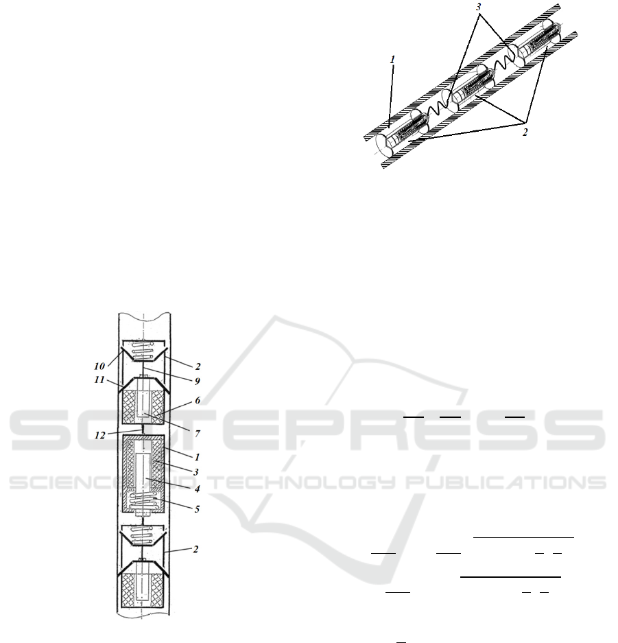
The in-pipe robotic module (Figure 1) consists of
middle link – mover 1 and two terminal links –
brakes 2. The mover is electromagnetic unit made of
solenoid coil 3 and ferromagnetic core 4. The
ferromagnetic core has a recoil spring 5. Two
terminal links have solenoid coil 6, ferromagnetic
core 7 and recoil spring 5. The ferromagnetic core 7
is supplied with adjustable brake element 9. It
provides brake effect during robot’s motion inside
the pipeline. The adjustable brake element 9
includes two lamellar elastic retainers 10 and 11
which are designed to provide significant brake
force in desired direction depending on
ferromagnetic core 7 position. The links are
interconnected by swivels 12. It provides turning of
the robot in pipeline bending. Such kind of robotic
design provides inspection of small diameter pipes
with sufficient speed and it can be used in such
environment as liquid.
Figure 1: The in-pipe robot with modules.
The design of each robotic module involves the
use of standard elements. The power supply system
consists of common micro batteries.
The principle of the robot’s movement is as
follows. The electromagnetic core is moving inside
the robot’s hull. It strikes the frontal part of the hull
and sends an impulse to it (Chaschukhin, 2008;
Rizzotto et al., 2003). Thus the hull starts moving
forward. After full stop of the hull the ferromagnetic
core returns back slowly. Meanwhile the hull stands
still due to friction force. The cycle then repeats.
Figure 2: The multilink in-pipe micro robot design: 1 –
pipe, 2 – robotic modules, 3 - interconnections.
The proposed design of the miniature robot has
no any moving parts outside the robot’s hull thus it
has increased reliability. The outer diameter of the
hull is smaller than the inner diameter of the pipe.
The figure 2 shows that the multilink micro robot
consists of several basic modules. The calculation
technique for the proposed design is based on energy
conservation law (Bolotnik et al., 2014). The process
of impacting the ferromagnetic core on the frontal
part of the robot’s hull is described as follows.
+=
+
+=
,
(1)
Here m and M are masses of the ferromagnetic
core and the hull; v and V are velocities of the
ferromagnetic core and the hull after impact; Q is
thermal energy which is known for the certain
design.
The solution for the system mentioned above is:
=
−
−1+
=
+
−1+
,
(2)
Here we can see that velocity of the hull grows
with →0,
→∞ Let us estimate the system after
impact. Let the ferromagnetic core has the position
coordinate along
axis, and the hull has the
position coordinate along
axis. The stiffness
coefficient of the spring let be , and the friction
force between adjustable brake element and the
pipeline inner surface let be
. Then the equations
of the system’s motion are the following.
=−
(
−
)
=−
(
−
)
+
,
(3)
The solution for the system will be the following:
Multilink Micro Robots Designed for Inspection in Pipes of Small Diameters
269
(
)
=
+
+
(
)
+
+
cos
(
)
+
sin
(
)
(
)
=
+
(
)
+
+
+
(
)
−
cos
(
)
−
−
sin
(
)
,
(4)
Here =
;
…
are constants.
If we suppose the system below to be the initial
condition
(
0
)
=
(
0
)
=
(
0
)
=
(
0
)
=
,
(5)
then for
…
constants we can obtain the next
result
=
+
−
(
)
=
−
=
−
+
(
)
=
(
−
)
,
(6)
The use of these equations requires experimental
clarification. But it can provide the evaluative
calculation of movement modes for different design
types of the robot.
3 THE IN-PIPE IMPACTLESS
MICRO ROBOTS
There is another way of motion for in-pipe micro
robots with the design mentioned above (Gradetsky
et al., 2011; Gradetsky et al., 2012; Virk, 2012). It
does not need any impacts to move (Figure 3).
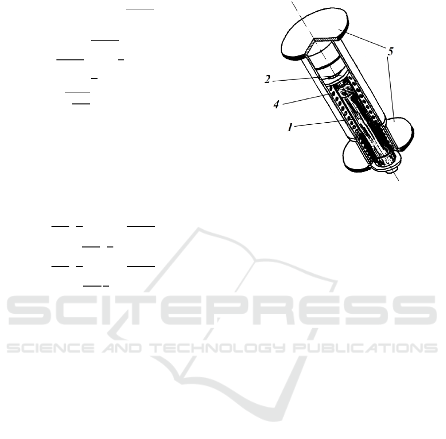
The design of such type of in-pipe robot includes
the Inner rod 1 and the Outer hull 2. The Inner rod
has the spring 3 that pushes the rod outside the hull
after voltage cut off in the electromagnetic coil 4.
The Inner rod and the Outer hull have their own
adjustable brake elements 5. Each brake element has
friction anisotropy (Pan, 2003.).
The design of such type of in-pipe robot includes
the Inner rod 1 and the Outer hull 2. The Inner rod
has the spring 3 that pushes the rod outside the hull
after voltage cut off in the electromagnetic coil 4.
The Inner rod and the Outer hull have their own
adjustable brake elements 5. Each brake element has
friction anisotropy (Pan, 2003.). Adjustable brake
Figure 3: The in-pipe impactless micro robot.
elements are designed to prevent backward moving.
Meanwhile the friction between the surface of the
pipe and the brake element is not enough to stop the
micro robot when it moves forward. When the robot
receives a task for moving it adjusts its brake
elements according to the desired direction. Then a
bunch of square impulses from the control unit come
to the electromagnetic coil. The cycle repeats in a
short time. Thus the robot moves under pulling and
pushing cycles.
The calculation technique for the motion
parameters of the robot is based on assumption that it
moves in rectilinear pipe which axis has an angle
with the horizon. Let
(=1,2) be absolute
coordinates of the Inner rod and the Outer hull along
that axis;
(=1,2) be masses of the Inner rod and
the Outer hull accordingly; the factor k be the stiffness
factor of the spring. The g is acceleration of gravity.
Initial points have been chosen with the assumption
that the spring is not deformed when
=
=0.
The Inner rod is pulled inside the electromagnetic coil
under electromagnetic force F. The elastic force of the
spring
|
−
|
is acting on the Inner rod and the
Outer hull. The other forces acting on the system are
gravity
and reaction forces
in brakes. The
force of dry friction
and the resistance force of
the environment
are also acting on the robot.
Here D stands for the resistance factor of the
environment that may vary for different parts of the
micro robot. Thus equations of motion for the robot
given as a system with two masses are the following:
=−+
(
−
)
−
−
sin
(
)
−
−
=−
(
−
)
−
−
sin
(
)
−
−
,
(7)
ICINCO 2016 - 13th International Conference on Informatics in Control, Automation and Robotics
270

=
,
(
<0
>
)
−
,
(
<0
<−
)
,
(
=0−
≤
≤
)
,
(8)
=
(
−1
)
−
(
−
)
−
−
sin
(
)
−
,=1,2,
(9)
Here
is the friction factor for brake element
under its moving along robot’s desired direction;
is the friction factor for brake element moving in
opposite robot’s desired direction.
The electromagnetic coil receives square
impulses periodically. The electromagnetic force F
can be described as:
=
=
,
(10)
Here W is the electromagnetic power, L is the
coil inductance, I is the current in the coil.
Using these equations is essential in motion
simulation and parametric optimization of the in-
pipe robot of impactless type of different design.
4 THE DESIGN AND
TECHNOLOGICAL
EQUIPMENT OF IN-PIPE
ROBOTS
Micro robots designed for moving in pipes can be
equipped with different technological equipment like
sensors for pipes diagnostic and inspection, cameras
with standard or infrared optics, communication
units and different tools for cleaning, drilling,
welding and cable pulling. Such robots can inspect
many environmental parameters like humidity,
temperature, radiation and so on.
The figure 4 shows the example of applying
micro camera to the designed robot.
Figure 4: Digital camera for in-pipe micro robot.
Using micro camera inside different pipes the
operator can receive desired information about the
inner condition of the pipe and presence of
extraneous objects.
Figure 5: View from the robot’s camera inside the
pipeline.
The figure 5 shows the camera view with
different objects in sight. These extraneous objects
can be deleted from the pipe with the robot.
The movement speed of the designed in-pipe
micro robot depends on impulses frequency
controlled by control system (Basem et al., 2012).
For the example the designed robot moves with the
speed of 6 sm/sec under impulses with frequency of
f equals 10 Hz. And for f equals 15 Hz the absolute
movement speed of the robot was 9 sm/sec. It took 2
minutes to pass 10 meters inside a pipe for the robot.
Characteristics of different in-pipe robots design are
shown on the table 1.
Table 1: In-pipe robot’s parameters.
Parameter Ver.1 Ver.2 Ver.3
Pipe diameter, mm 5 10 20
Motor type Electromagnetic
Supply voltage, V 6-10 10-15 15-20
Current, A 0.4 1.0 1.5
Impulse frequency, Hz 4-20 4-30 4-70
Power consumption,
W
3.2-
4.0
10-15 22.5-
30.0
Movement speed,
mm/sec
4-10 6-20 6-30
Position error, mm 0.5 0.7 0.8
Fillet radius of the
pipe, mm
100 400 600
Movement range, m 10 50 70
Payload, N 0.05 0.5 2.0
Multilink Micro Robots Designed for Inspection in Pipes of Small Diameters
271
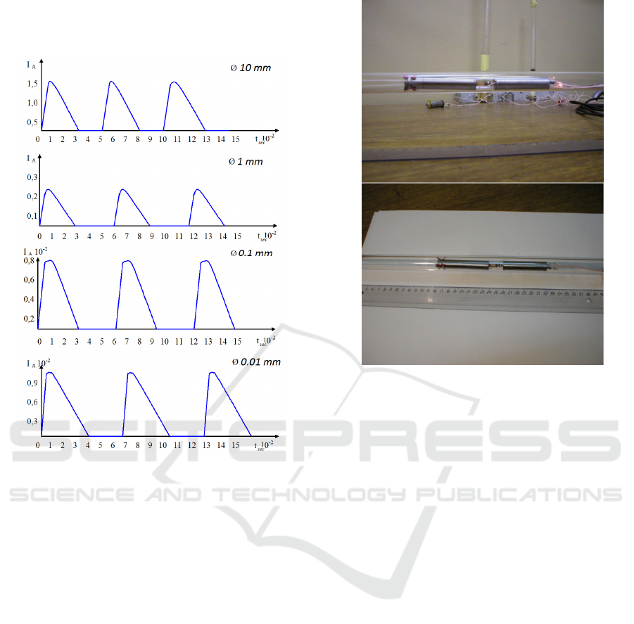
The dynamics research of the designed robot
showed that its motion inside of pipelines of
different diameters is aperiodic in nature.
Figure 6: View from the robot’s camera inside the
pipeline.
Figure 6 shows control signals form depending on
different electromagnetic core diameters inside the
coil.
Research of the speed of micro robots in pipes of
small diameters was conducted under different
environmental conditions like absence and presence
of excess pressure in the system.
The use of high precision sensors onboard the
robot allows to obtain information about the
environment inside a pipe with high accuracy.
In the designed in-pipe micro robot is controlled
in supervision mode. The information obtained by
the sensors and camera is transmitted to the operator
on the control panel. The operator takes a decision
and sends a command to the signal line by a time–
pulse coding. The use of this form of transmission of
control signals enables one signal wire to transmit
up to eight commands.
Figure 7: overview of the designed robotic modules.
5 CONCLUSIONS
The proposed design of the in-pipe robot may be
used in experimental investigation of different
inspection techniques. The method of determining
the speed of micro robot allows finding the speed of
micro robot when it moves in different environments
with different viscosity under the absence and
presence of excessive pressure in the piping system.
ACKNOWLEDGEMENTS
Current work is supported by Russian Science
Foundation grant № 14-11-00298.
REFERENCES
Valdastri, P., Webster III, R.J., Quaglia, C., Quirini, M.,
Menciassi, A., Dario, P. 2009. A new mechanism for
mesoscale legged locomotion in compliant tubular
environments. IEEE Transactions on Robotics 25(5),
1047-1057,
Becker, F., Minchenya, V., Zimmermann K., and Zeidis,
I., 2010. “Single Piezo Actuator Driven Micro Robots
for 2-dimensional Locomotion,” Electron. Proceedings
ICINCO 2016 - 13th International Conference on Informatics in Control, Automation and Robotics
272

of Workshop on Microactuators and
Micromechanisms, Aachen, Germany,
Gradetsky, V., Pushkin, M., Rachkov, M., 1998. Control
motion of two-links mobile robot with flexible
connections. Proc. Of the 4
th
Int. Conf. on Advanced
Robotics, Intelligent Automation and Active Systems,
Moscow, P. 102-107.
Gradetsky, V., Knyazkov, M., Kravchuk, L., Semyonov,
E., 2005. Motion techniques of micro in-pipe robots,
Journal of Microsystems Engineering, №9, in Russian.
Gradetsky, V., Knyazkov, M., Semyonov, E., 2005.
Adaptive motion of mechatronic macro and micro
systems, International Symposium on Adaptive and
Intellectual Robotics, Moscow, P. 83-93, in Russian.
Gradetsky, V., Solovtsov, M., Rizotto, G.G., Amato, P.,
2003. Modular Design of Electro-Magnetic
Mechatronic Microrobots, Proc. of the 6
th
CLAWAR
2003 Int. Conf., Italy, P. 651-658.
Chaschukhin, V., 2008. Dynamics Simulation and Control
Parameters Definition of the In-pipe Micro Robot,
Journal Theory and Control Systems, №5, P. 142-147,
in Russian.
Rizzotto, G.G., Amato, P., Gradetsky, V., Solovtsov, V.,
Kniazkov, M. 2003. Simulation and Modeling of
Electro-Magnetic Mechatronic Microsystems. // Proc.
of the IARP Intern. Conf. on Microrobots,
Micromachines and Microsystems, Moscow, April 24-
25,
Bolotnik, N.N., Chernousko, F.L., Gradetsky, V.G.,
Knyazkov, M.M. 2014. Motion principles for
designing biologically inspired robots // Proceedings
of the Conference-Workshop “Bio-inspired Robotics”,
Italy, Frascati – ENEA, 14-15 May, P. 84-90.
Gradetsky, V., Veshnikov, V.B., Chashchukhin, V. 2011.
Simulation Using Mobile Multilink Robot with a
Virtual Reality Vision System// Using Robots in
Hazardous Environments,Woodhead Publishing Ltd.,
pp. 499-519,
Gradetsky, V.G., Ermolov, I.L., Knyazkov, M.M.,
Poduraev, J.V. 2012. Miniature robots and modern
technologies // Proceedings of the 43rd International
Symposium on Robotics (ISR 2012), Taipei, Taiwan,
August 29031, P. 271-276.
Virk, R.Z. 2012, "“Uniball” A Novel Method Of
Movementfor Pipe Climbing Robots Gurvinder",
Proceedings of the Fifteenth International Conference
on Climbing and Walking Robots and the Support
Technologies for Mobile Machines, Baltimore, MD,
USA, 23 – 26 July рр.305-312.
Pan, Z., 2003. “Miniature pipe robots”, Industrial Robot:
An International Journal, 30(6), p. 575–83.
Basem, F.Y., et al, 2012. "IN-PIPE INSPECTION
ROBOT", Proceedings of the Fifteenth International
Conference on Climbing and Walking Robots and the
Support Technologies for Mobile Machines,
Baltimore, MD, USA, 23 – 26 July рр.289-296.
Multilink Micro Robots Designed for Inspection in Pipes of Small Diameters
273
