
Subtask Scheduling and Predictive-Delay Control
Comparison and Hybridization
Zakaria Sahraoui
1
, Abdenour Labed
1
, Mohamed Ahmed-Nacer
2
and Emmanuel Grolleau
3
1
Computer Science Department,
´
Ecole Militaire Polytechnique, BP 17, Bordj-Elbahri, Algiers, Algeria
2
Computer Science Department, Universit
´
e des Sciences et de la Technologie HOUARI BOUMEDIENE, Algiers, Algeria
3
LIAS, ENSMA, T
´
el
´
eport 2,1, Av. Cl
´
ement Ader, BP 40109, 86961 Chasseneuil Futuroscope, Cedex, France
Keywords:
Input-output Latency, Subtask Scheduling, Real-time control, Predictive-Delay, Quality of Control,
Feedback-scheduling, TrueTime.
Abstract:
Amongst real-time scheduling community, several methods aim at enhencing the performance of the control.
Subtask scheduling is one of the embedded convenient methods that reduce the input-output latency in the
control loops. The predictive-Delay control is a new method based on input-output latency prediction in order
to reduce the impact of this artefact on the quality of the control. Combining both subtask scheduling and
predictive delay methods can be of a great help in combatting the impairments induced by this scheduling
artifact.
1 INTRODUCTION
In real-time multi-task control, the choice of per-
formance criteria is guided by multiple design con-
straints. On one hand, a part of these constraints is
related to control design, whereas the others rely on
the real-time scheduling theory. But the challenging
question is what can be the dependence between the
two sides of these constraints ?
For instance, it is well-known that in control the-
ory, selection of appropriate task periods is one of
the most prevailing constraints, while in scheduling
theory, the processor overload is a fundamental con-
straint. The choice of a processor in an embedded sys-
tem is initially based on these two parameters, which
means that there is a relationship between the pe-
riod and the processor load. Furthermore, insuring
schedulability does not necessarily mean control with
high performance, and reducing the task periods is not
necessarily increasing the quality of control (Sahraoui
et al., 2016). More explicitly, since control tasks are
of recurrent nature, the first step in control design is
to identify the closed loop frequency of the controlled
process which provides a first idea about the control
task periods. As a matter of fact, with coarse values of
the execution times in hand, an estimate of the proces-
sor load and at the same time its capacity are generally
deduced from the control task periods.
In this context, some recent theories and research
results may be of valuable help. For example, in
(Cervin, 2003)(Sahraoui et al., 2014), it has been
shown that a higher processor bound test does not
necessarily lead to a better quality of control. It has
also been proven that input-output latency, is a signif-
icant artifact which may deteriorate the control if it is
not taken into account.
In this context, we aim through the present work at
testing the quality of the control for second and third
order processes under the subtask model conditions.
The main points of the analysis 0out in (Sahraoui
et al., 2014) are resumed to focus the variation of
some parameters.
The execution time confidence interval is widened
to ensure convergent behavior of the quality of the
control (QC) in the simulation set. Execution-time
with a wider confidence interval may also mean a
mode change. This also can reveal overload situa-
tion required to highlight some scheduling artefacts.
These characterizations give more in deep sight and
help the reader discern between the extent of research
works.
In this paper, using two case studies and inten-
sive simulation where computing duration varies, we
first show that classic FBS fails in stabilizing pro-
cesses controlled by low priority tasks in case of pro-
cessor overload. We show that both subtask schedul-
ing method studied in (Cervin, 2003) and Predictive-
Delay Control (P-DC) proposed in (Sahraoui et al.,
Sahraoui, Z., Labed, A., Ahmed-Nacer, M. and Grolleau, E.
Subtask Scheduling and Predictive-Delay Control - Comparison and Hybridization.
DOI: 10.5220/0005977701010109
In Proceedings of the 6th International Conference on Simulation and Modeling Methodologies, Technologies and Applications (SIMULTECH 2016), pages 101-109
ISBN: 978-989-758-199-1
Copyright
c
2016 by SCITEPRESS – Science and Technology Publications, Lda. All rights reserved
101

2016) improve the QC. Finally, after this analysis and
comparison, we show that combining both of these
methods leads to even better result.
2 PREVIOUS WORKS
Several Works have studied the scheduling and con-
trol codesign problem. They generally investigate
methods either able to enhance the control perfor-
mance or to recover the process stability. The real-
time community have been working on this subject
for 20 years. The seminal work presented in (Seto
et al., 1996), solves an optimization problem based
on a non linear criterion, then in (Ryu et al., 1997)
other criteria are proposed for the optimization of
control performance as a function of the period and
the computing latency. Later, there has been sugges-
tions to resolve other optimization problems on-line
to fit the scheduling constraints as schedulability or
task periods selection, like in (Robert et al., 2005)
by RST & H∞ algorithms together or by the LPV
method (Sename et al., 2008; Robert et al., 2010) .
These solutions are referred to as the indirect feed-
back scheduling (FBS).
Methods that suggest priority assignment, like in
(Xu et al., 2014) with the LQG method or in (Bini
and Cervin, 2008; Yepez et al., 2003; Xia et al., 2006)
are called direct FBS. In the class of the direct FBS
we also find the solution of (Henriksson et al., 2002;
Henriksson and
˚
Akesson, 2004) based on the Predic-
tive Control Model.
Particularly, authors in (Cervin and Eker, 2000;
Cervin, 2003) have studied the impact of the schedul-
ing jitters on the QC using the jitterbug tool (Cervin,
2003) and then those of the latencies on the QC us-
ing the TrueTime tool (Cervin et al., 2003). The au-
thors, proposed an indirect FBS to rescale tasks pe-
riods, based on a processor load estimator. Then,
this study has been taken back in-details in (Sahraoui
et al., 2014)(Sahraoui et al., 2016), where it is ac-
counted for other scheduling artefacts and constraints.
For more details about feedback scheduling the reader
can refer to (Sahraoui et al., 2014).
Regarding the subtask solution, it is considered by
(Gerber and Hong, 1993; Gerber and Hong, 1997) in
order to enhance the schedulability under fixed prior-
ity (FP) scheduling or by (Crespo et al., 1999; Alber-
tos and Crespo, 1999; Balbastre et al., 2000) to mini-
mize the input-output jitter. Finally, in (Cervin, 2003)
the subtask scheduling is used to improve the QC.
3 TASK MODEL AND
EXPERIMENTAL SETTINGS
Lets first introduce the classical task model with the
associated notation: we call tasks system the set of
tasks S ={τ
1
,...τ
N
} involved in a given real-time sys-
tem and denote the number of tasks by N. In addi-
tion, two jobs of a task are considered perfectly inter-
changeable in that they perform identical treatment.
A given task τ
i
is characterized by its period h
i
,
its observed execution-time C
i
(k) at time index k, its
worst execution time C
i
and the date of its first arrival
(or offset) O
i
. The tasks systems studied in this work
have implicit-deadlines (i.e., tasks must terminate be-
fore their next release). Each periodic task generates
a potentially infinite set of jobs τ
i
(k), where k refers
to the k
th
sampling period : every sub-request job is
released every h
i
time unit.
3.1 Task Division into Calculate-Output
and Update-State
A typical model to get the minimum latency from the
measure input to the control output is to split the con-
troller code into two segments: Calculate-Output and
Update-State. The control output is send to the pro-
cess before the Update-State segment (
˚
Astr
¨
om and
Wittenmark, 1997), see Listing 1. We implement the
P-DC with this model for two reasons:
i) to conform, in terms of matching and compari-
son, the P-DC method with the subtask schedul-
ing which is based on this typical model,
ii) to check the efficiency of this method with the
minimum of latencies not due to scheduling ar-
tifacts.
In Figure 1 the execution time of the Calculate-Output
segment C
co
is a rate of C
i
(k) (in %). This means that
the delay from the jobs start time to the end of the
Calculate-Output segment will be at least C
co
C
i
(k).
However, preemption from higher priority tasks may
induce a longer delay, where the time from the jobs re-
lease/arrival time until its start time is noted the sam-
pling latency Ls and Lio is the Input-Output latency
representing the C
co
segment latency.
The second segment returns C
us
(%) of C
i
(k),
which is reserved to update the PID state variables.
This duration can be also subject of preemption from
higher priority tasks and noted by Lus as an Update-
State Latency. Finally the response time latency is
defined by
Lresp = Ls +Lio + Lus .
SIMULTECH 2016 - 6th International Conference on Simulation and Modeling Methodologies, Technologies and Applications
102
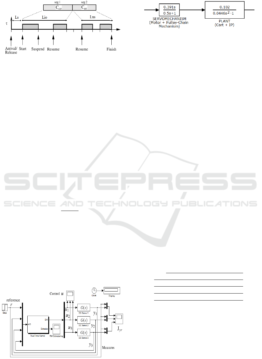
Figure 1: Task division into Calculate-Output and Update-
State.
It is important to know that in the P-DC method the
task scheduling is assumed by the RM scheduler un-
der the FBS. Nevertheless, in subtask scheduling, we
assign the priorities to the tasks segments (subtask
model) where the scheduling is assumed with the
FP protocol. This technique is proposed in (Cervin,
2003) and implemented under the TrueTime tool. The
subtask scheduling method is detailed in section 4.
In the sequel, we specify the used FBS as well
as the servo-motor and the pendulum processes to be
controlled with a PID controller and finally specify
the cost criterion of the QC.
3.2 Physical Processes
The first case study application presented in Figure 2
concerns three second order processes. It consists of
three similar servo-motors, each one described by the
transfer function
G(s)=
1000
s(s +1)
. (1)
We define by r the reference signal, y
i
the mea-
sure of i
th
process and u
i
the control send to this pro-
cess. The second case study consists of three inverted-
pendulum which are a convolution of the inverted
pendulums, carts, motors and the pulley chain mech-
anisms as specified by the transfer functions (Figure
3).
The Inverted pendulum is often considered as ref-
erence benchmark in control design problems. For
Figure 2: Three servo-motors under TrueTime/Simulink.
Figure 3: The inverted pendulum, version on cart.
our simulation, the pendulum starts from the center
which corresponds to an angle of 0 rad. It will be
constrained to an impulsion of 0.0873 rad (about 5
degrees), applied on the cart two seconds after the be-
ginning of the simulation.
3.3 Feedback Scheduling
The FBS is used on-line, generally to supersede the
off-line scheduling analysis.
Job durations of the three controller tasks τ
1
, τ
2
and τ
3
are generated according to a Weibull distribu-
tion as in (Sahraoui et al., 2016). This distribution is
defined by three parameters : the localization param-
eter l which fixes the best case execution-time, the
shape factor λ and the scale factor µ. Variation in task
execution-times during the simulation is accompanied
by task periods rescaling, in order to achieve an ob-
served processor utilization equal to the Liu and Lay-
land (L&L) (Liu and Layland, 1973) RM utilization
bound.
At the end of each job τ
i
(k), the execution time
ˆ
C
i
(k) is smoothed by a low pass filter. The FBS relies
on this value, to calculate an estimate for the CPU
utilization factor
ˆ
U(t)=
∑
N
i=1
ˆ
C
i
(k)/h
i
(t).
3.4 Tasks Systems
The tasks systems used in the present work are de-
scribed in Tables 1 and 2, where durations are given
in ms.
Table 1: The three servo-motors tasks system for scheduling
artifacts characterization.
h
nom
i
C
i
l µ λ
τ
1
6 4 3.1 0.0009 3
τ
2
13 4 3.1 0.0009 3
τ
3
14 4 3.1 0.0009 3
The shape factor µ is chosen high enough to ensure
wide confident interval of the C
i
(k) values. This may
not introduce processor overload situation in simu-
lations, but such situation can occur for the subtask
scheduling case.
The system defined in Table 2 is simulated with
the same range of processor utilization U
i
as in the
three servo-motors example, where periods and exe-
cution times are both multiplied by a factor of 1.6. It
Subtask Scheduling and Predictive-Delay Control - Comparison and Hybridization
103

is worth noting that the task sampling period never ex-
ceeds the divergence threshold of 27 ms for the servo-
motor and 60 ms for the inverted pendulum. These
thresholds are related to the PID setting described in
the next subsection.
Table 2: The inverted pendulums tasks system characteriza-
tion.
h
nom
i
C
i
l µ λ
τ
1
9.6 7.5 5 0.0014 3
τ
2
20.8 7.5 5 0.0014 3
τ
3
22.4 7.5 5 0.0014 3
3.5 PID Controller
The PID controller defined by equations (2-7) is
used. This controller is developed in (
˚
Astr
¨
om and
H
¨
agglund, 1995). Given the fact that we rescale peri-
ods by FBS to ensure estimated schedulability, a
d
and
b
d
parameters are recomputed according to formulas
(5) and (6). Thus, a derivative term is computed using
backward differences and a low pass filter (equation
(4)) is used.
P(k) = K(β ∗r(k)−y(t
k
)), (2)
I(k) = I(k −1)+K ∗
h
T
i
(r(k)−y(t
k
)), (3)
D(k) = a
d
∗D(k −1)+b
d
∗(y(t
k−1
)−y(t
k
)),(4)
a
d
=
T
d
N ∗h +T
d
, (5)
b
d
=
N ∗K ∗T
d
N ∗h +T
d
, (6)
u(k) = P(k)+I(k)+D(k). (7)
PID parameters (K, T
i
, T
d
, N) are tuned in a way
to obtain a system closed-loop bandwidth of ω
c
=
20 rd/s and a relative damping ξ = 0.707. This ex-
cludes the fact that the controller design and dis-
cretization may be a source of instability for the range
of the sampling periods h
i
. For such convergence the
cost (8) has been specified to respect a threshold of
0.36. This outset for divergent costs is taken for a
simulation time T
sim
=5 ms.
J
yr
i
=
T
sim
∫
0
∣r −y
i
∣dt . (8)
3.6 Impact of the Input-output Latency
on QC
For the tasks system presented in Table1, the QC may
diverge because of high input-output latency of lower
priority tasks, due to preemption from tasks of higher
priority level. Figure 4 confirms this behavior. The
motor controlled by the task τ
3
diverges.
0 2 4 6 8 10
−5
0
5
x 10
5
τ
3
0 2 4 6 8 10
0
0.5
1
τ
2
0 2 4 6 8 10
0
0.5
1
τ
1
r y
Figure 4: The three servo-motors example with the subtask
model and wide range of C
i
(k).
4 SUBTASK SCHEDULING
To simulate the subtask scheduling, the task model
presented in subsection 3.1 is used. With a fixed
priority assignment scheduling protocol, we assign
the highest priority to the Calculate-Output segment
(time critical part) and the lowest priority to the
Update-State segment (must respect the period as
deadline). It is obvious that the improvement will
concern τ
3
, the task which has the lowest priority.
Nevertheless, for overload situation, it can happen
that τ
3
is blocked most of the time.
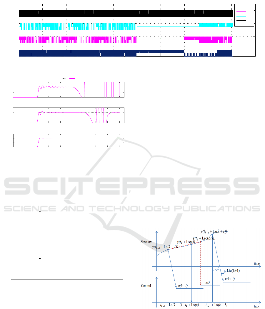
Scheduling of this case is shown in figure 5. The
output measure y
i
for each task τ
i
of the tasks system
defined in Table1 is shown in Figure 6.
Undesirable breaks in the diagram testify the over-
load situation under subtask scheduling method. In
this marginal case, tasks τ
2
and τ
3
are concerned
within the interval times [2.5, 3.5] and [2.5 3.8], re-
spectively. Figure 6 shows the divergence of tasks
with lower priority τ
3
and then τ
2
as a consequence
to the overload situation.
4.1 Schedulability
It is noted in (Cervin, 2003) that the ideal case of
subtask scheduling under FP scheduling suggests that
all Calculate-Output tasks segments have higher pri-
orities than all Update-State tasks segments. Un-
fortunately, such priority assignment may render the
tasks system unschedulable. In cases where this ap-
proach does not work, an iterative algorithm is used.
Given a schedulable original tasks system, the iter-
ative algorithm attempts to minimize the deadlines
of the Calculate-Output segments while maintaining
schedulability.
SIMULTECH 2016 - 6th International Conference on Simulation and Modeling Methodologies, Technologies and Applications
104
0 0.5 1 1.5 2 2.5 3 3.5 4 4.5 5
1
1.5
2
2.5
3
3.5
4
4.5
5
τ
1
τ
2
τ
3
FBS
Figure 5: Scheduling diagram of the three servo-motors example with the subtask scheduling method under overload situation.
0 0.5 1 1.5 2 2.5 3 3.5 4 4.5
0
0.5
1
1.5
τ
1
0 0.5 1 1.5 2 2.5 3 3.5 4 4.5
0
0.5
1
1.5
τ
2
0 0.5 1 1.5 2 2.5 3 3.5 4 4.5
0
0.5
1
1.5
τ
3
r
i
y
i
Figure 6: Output measures of the three servo-motors ex-
ample with the subtask scheduling method under overload
situation.
Listing 1: Implementation of subtask scheduling under
fixed priority scheduling.
1 t := CurrentTime;
2 SetPriority(P CO);
3 LOOP
4 ReadInput;
5 Calculate−Output;
6 WriteOutput;
7 SetPriority(P US);
8 Update−State;
9 t := t + h;
10 SetPriority(P CO);
11 SleepUntil(t);
12 END;
13 }
In our work, the used FBS does not care about
job overruns and the basic FP implementation tech-
nique of (Cervin, 2003) is used. Since the TrueTime
tool supports dynamic changes of priorities, we sim-
ply insert the TrueTime instruction “SetPriority” in
the code when entering a new segment (i.e., subtask
in this model), see Listing 1. Note that the priority
changes may introduce additional context switches,
which can degrade the performance in a real system.
It has been established in (Cervin, 2003) that the
input-output latency Lio is reduced to 42 % and the
used cost (an LQG function based on the control and
the output signals), is reduced up to 26 %. Neverthe-
less, it is also noted that even if the latency is fixed and
known, delay compensation can only recover part of
the performance loss. This fact is illustrated by an ex-
ample where the control cost of an integrator is given
by J ≈0.79h +L, for details, see (Cervin, 2003).
5 PREDICTIVE-DELAY
CONTROL
To improve the QC, the P-DC method brings up a pre-
dicted response time latency Lresp
i
of the concerned
task τ
i
to calculate the control signal u
i
. This arti-
fice helps bypassing several practical problems like
schedulability, convergence and computation time
from which suffer most of proposed solutions. The
method relies on an estimate Lresp
i
, the current and
the previous measures to extrapolate the forthcoming
measure y
i
required in the PID control calculus. With-
out the P-DC, the measure to be used in the PID will
be obsolete. reference
Figure 7: Predictive measures based on Lio (Sahraoui et al.,
2016).
With the observed C
i
(k), within the overloaded
case of the subtask simulation of section 4 we obtain
the P-DC result presented in figures 8 and 9.
Subtask Scheduling and Predictive-Delay Control - Comparison and Hybridization
105
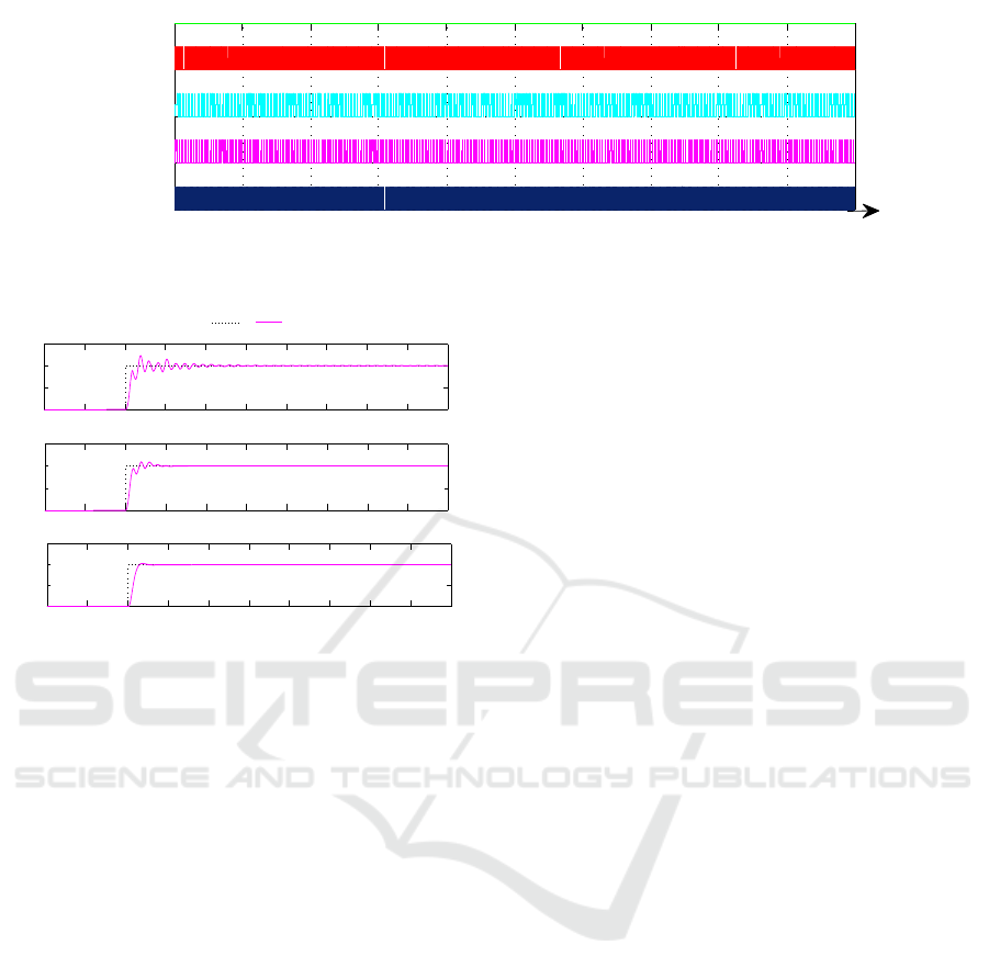
0 0.5 1 1.5 2 2.5 3 3.5 4 4.5 5
1
2
3
4
5
time(s)
FBS
τ
3
τ
2
τ
1
Figure 8: Scheduling of three servo-motors under P-DC with an estimate Lresp.
0 0.5 1 1.5 2 2.5 3 3.5 4 4.5 5
0
0.5
1
1.5
τ
1
0 0.5 1 1.5 2 2.5 3 3.5 4 4.5 5
0
0.5
1
1.5
τ
2
0 0.5 1 1.5 2 2.5 3 3.5 4 4.5 5
0
0.5
1
1.5
time(s)
τ
3
r
i
y
i
Figure 9: The three servo-motors controls converge to the
set point with a low cost for an overloaded system.
6 COMPARISON AND
HYBRIDIZATION
The first column in Table 3 sums up a comparison
among seven solutions proposed to enhance the QC
of tasks τ
2
and τ
3
without hybridization. Column two,
summarize a comparison when the hybridization so-
lution is involved.
We observe that when the hybrid solution is not
involved in the comparison tests, for mild to moder-
ate deterioration as in the case of task τ
2
, or for ob-
vious deterioration like in the case of task τ
3
, using
estimated Lresp (line 4,5) or its previous values (line
2 and 3), the P-DC solution may be of great help.
It is observed through more than 20000 simula-
tions that the improvement amounts of divergent con-
trols (e.g., Figure 10.a), based either on the previous
or on an estimated Lio which are computed on the
basis of the previous and an estimated Lresp, respec-
tively is sensibly the same. Figure 10.c shows the QC
improvement when using actual Lio in case of task τ
3
.
This result is not far from the improvement based on
the subtask solution shown in Figure 10.b.
It can be concluded that subtask scheduling com-
bined with P-DC leads to a solution that outperforms
those obtained using P-DC or the subtask scheduling
solely whatever the task is (Figure 10.d show the step
response of the task τ
3
with a J
yr
i
lower than 0.007).
Implementation of solutions based on the previ-
ous Lresp or Lio needs system calls to save the re-
sponse time and eventually the sampling latency for
each job termination. However, solutions with the
response-time calculated on the basis of upper bounds
may show significant improvements.
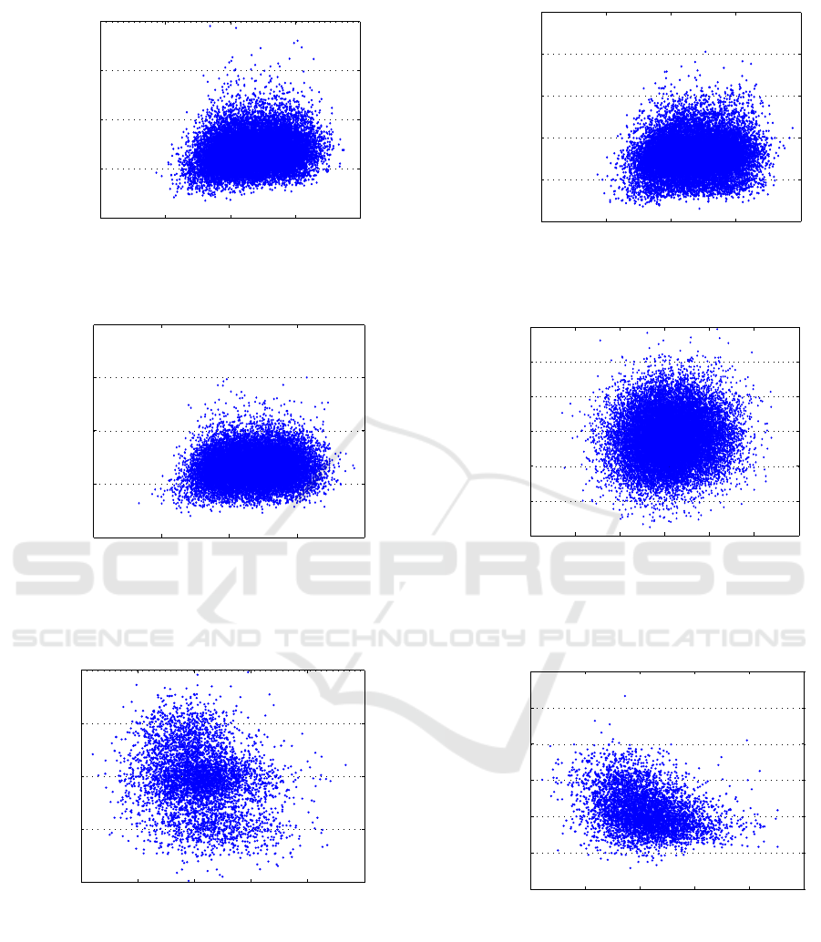
To verify these results, we plot the Lio impact on
the QC of the 20000 samples for each technique. Fig-
ure 11.a shows the improvement of the QC when the
previous value of Lio is used as an estimate. The re-
sult in Figure 11.b is based on actual Lio and is similar
to the one obtained when the previous Lio is used.
The smoothed Lio in Figure 11.c, can be consid-
ered as the easiest prediction if we use a simple filter;
the same as the one used to smooth the execution-time
values. Figure 11.d, show the QC of the hybride so-
lution which gives the best cost where J
yr
3
is always
lower than 0.12 <0.15. In all the tested cases, it is no-
ticed that J
yr
3
never exceeds the value of 0.36 which is
considered as a threshold in our specification (section
3.2).
It is also important to recall that, due to the over-
load situation, it was very difficult to accomplish the
20000 simulations samples for subtask solution.
For the example of the inverted pendulum, which
is considered as a benchmark with a more sensitive
cost, where J
yr
<0.09 for convergent control situation.
Figures 12.a and 12.b show the impact of the
input-output latency on the QC for 20000 simulation
samples of 5 s. The Cost J
yr
3
converges for all the
samples, which confirms the result obtained for the
first example of three servo-motors.
It is also noticed that the P-DC method is more
appropriate for impulse response systems like in the
pendulum case.
SIMULTECH 2016 - 6th International Conference on Simulation and Modeling Methodologies, Technologies and Applications
106
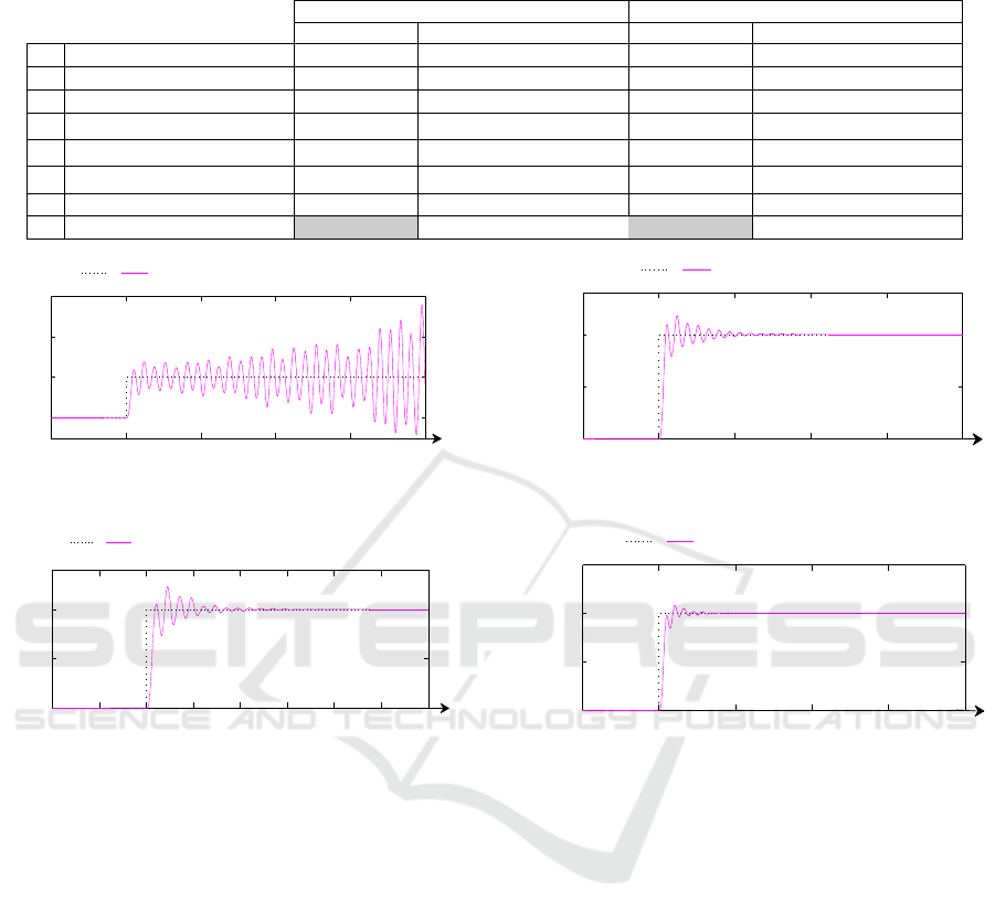
Table 3: Summary statement in comparison and hybridization between subtask scheduling and P-DC for the case of the three
servo-motors.
τ
2
τ
3
Comparison Hybridization involved Comparison Hybridization involved
1 Actual Lio 0% 0% 31% 1%
2 Previous Lio 0% 4% 22% 0%
3 Previous Lresp 0% 4% 0% 0%
4 Lresp
ub
(WCET) 79% 0% 0% 0%
5 Lresp
ub
(
ˆ
C
i
(k)) 0% 0% 0% 0%
6 Smoothed Lresp
ub
(
ˆ
C
i
(k)) 0% 51% 0.5% 0%
7 Subtask only 21% 0% 46.5% 0%
8 Subtask & P-DC 41% 99%
0 1 2 3 4 5
0
1
2
3
time(s)
τ
3
r Divergent output y with conventional method
J
yr3
= 2.86
(a)
0 1 2 3 4 5
0
0.5
1
time(s)
τ
3
r Outpout y for Subtask Method
J
yr3
= 0.11
(b)
0 0.5 1 1.5 2 2.5 3 3.5 4
0
0.5
1
time(s)
τ
3
r
output y with P−DC method based on Lio
act
J
yr3
= 0.11
(c)
0 1 2 3 4 5
0
0.5
1
1.5
time(s)
τ
3
r Output y for Subtask and P−DC method
Jyr
3
= 0.007
(d)
Figure 10: Output and costs for a divergent QC (a) and for improved QC (b, c, d), case of the three servo-motors.
7 CONCLUSIONS
A comparison between the P-DC and the subtask
scheduling techniques is performed experimentally
by simulation under TrueTime tool. We found out
that the hybridization of both techniques under an FP
protocol is a promising path that helps improving sig-
nificantly the quality of the control.
Indeed, hybridization can suggest a better qual-
ity than a scheduling or a feedback scheduling based
solely on the Predictive-Delay control. Hence, it can
be deduced that the Predictive-Delay Control would
be used not only to make up for scheduling latency
but also to recover the control signal in overload/over-
run situations. This recovering should be difficult
to handle under indirect feedback scheduling or any
other scheduling algorithm like the subtask schedul-
ing techniques.
To sum up concluding remarks; reducing the
input-output latency, through a subtask scheduling
technique, can help boosting the P-DC method.
For further works, we can compare the P-DC
technique with other methods like the control server
(Aminifar et al., 2013) or the subtask scheduling un-
der the Earliest deadline first (EDF) scheduler, where
some other techniques to avoid overruns or overload
situations are suggested.
REFERENCES
Albertos, P. and Crespo, A. (1999). Real-time control of
non-uniformly sampled systems. Control Engineering
Practice, 7(4):445–458.
Aminifar, A., Bini, E., Eles, P., and Peng, Z. (2013).
Designing bandwidth-efficient stabilizing control
Subtask Scheduling and Predictive-Delay Control - Comparison and Hybridization
107
7 7.5 8 8.5 9
0.05
0.1
0.15
0.2
0.25
Lio
3
(k − 1)(m s)
J
y r3
(a)
7 7.5 8 8.5 9
0.05
0.1
0.15
0.2
0.25
0.3
ActualLio
3
(ms)
J
y r3
(b)
7 7.5 8 8.5 9
0.05
0.1
0.15
0.2
0.25
ˆ
Lio
3
(ms)
J
y r3
(c)
8.6 8.8 9 9.2 9.4 9.6 9.8
0.06
0.07
0.08
0.09
0.1
0.11
0.12
P-DC and Lio
3
(k − 1)(ms)
J
y r3
(d)
Figure 11: Improved QC and performances comparison between proposed solutions, case of the three servo-motors
12.5 13 13.5 14 14.5 15
0.046
0.048
0.05
0.052
0.054
Actual Lio
3
(ms)
J
y r
3
(a)
12.5 13 13.5 14 14.5 15
0.046
0.048
0.05
0.052
0.054
0.056
0.058
Lio
3
(ms)
J
y r
3
(b)
Figure 12: Improved QC and performance comparison, case of the three Inverted Pendulum.
servers. In Proceedings of 34th IEEE Real-Time Sys-
tems Symposium (RTSS), pages 298–307, Vancouver,
British Columbia. IEEE.
˚
Astr
¨
om, K. J. and H
¨
agglund, T. (1995). PID controllers :
Theory, design, and tuning - 2nd ed. Instrument Soci-
ety of America, 1995.
˚
Astr
¨
om, K. J. and Wittenmark, B. (1997). Computer-
controlled Systems (3rd Ed.). Prentice-Hall, Inc., Up-
per Saddle River, NJ, USA.
Balbastre, P., Ripoll, I., and Crespo, A. (2000). Con-
trol tasks delay reduction under static and dynamic
scheduling policies. In Real-Time Computing Systems
and Applications, 2000. Proceedings. Seventh Inter-
national Conference on, pages 522–526. IEEE.
SIMULTECH 2016 - 6th International Conference on Simulation and Modeling Methodologies, Technologies and Applications
108

Bini, E. and Cervin, A. (2008). Delay-aware period as-
signment in control systems. In Proceedings of the
Real-Time Systems Symposium (RTSS), pages 291–
300, Barcelona, Spain. IEEE.
Cervin, A. (2003). Integrated Control and Real-Time
Scheduling. PhD thesis, Lund University.
Cervin, A. and Eker, J. (2000). Feedback scheduling of
control tasks. In Decision and Control, 2000. Pro-
ceedings of the 39th IEEE Conference on, volume 5,
pages 4871–4876 vol.5.
Cervin, A., Henriksson, D., Lincoln, B., Eker, J., and
˚
Arz
´
en,
K.-E. (2003). How does control timing affect perfor-
mance ? Analysis and simulation of timing using Jit-
terbug and TrueTime. IEEE Control Systems Maga-
zine, 23(3):16–30.
Crespo, A., Ripoll, I., and Albertos, P. (1999). Reducing
delays in rt control: the control action interval. In
Proceedings of the 14th IFAC World Congress, pages
257–262.
Gerber, R. and Hong, S. (1993). Semantics-based compiler
transformations for enhanced schedulability. Citeseer.
Gerber, R. and Hong, S. (1997). Slicing real-time pro-
grams for enhanced schedulability. ACM Transactions
on Programming Languages and Systems (TOPLAS),
19(3):525–555.
Henriksson, D. and
˚
Akesson, J. (2004). Flexible Imple-
mentation of Model Predictive Control Using Sub-
optimal Solutions. Institutionen f
¨
or reglerteknik,
Lunds tekniska h
¨
ogskola. Lund University.
Henriksson, D., Cervin, A.,
˚
Akesson, J., and
˚
Arz
´
en, K.-E.
(2002). On dynamic real-time scheduling of model
predictive controllers. In Proceedings of the 41st IEEE
Conference on Decision and Control, volume 2, pages
1325–1330, Las Vegas, NV.
Liu, C. L. and Layland, J. W. (1973). Scheduling algo-
rithms for multiprogramming in a hard-real-time en-
vironment. Journal of the ACM (JACM), 20(1):46–61.
Robert, D., Sename, O., and Simon, D. (2005). Sam-
pling period dependent RST controller used in con-
trol/scheduling co-design. In Proceedings of the 16th
International Federation of Automatic Control (IFAC)
World Conference, Czech Republic.
Robert, D., Sename, O., and Simon, D. (2010). An H
∞
LPV design for sampling varying controllers experi-
mentation with a T-inverted pendulum. IEEE Trans-
actions on Control Systems Technology,, 18(3):741–
749.
Ryu, M., Hong, S., and Saksena, M. (1997). Streamlining
real-time controller design : From performance spec-
ifications to end-to-end timing constraints. In Pro-
ceedings of the Third IEEE Real-Time Technology and
Applications Symposium (RTAS), pages 91–99, Mon-
treal, Canada.
Sahraoui, Z., Grolleau, E., Mehdi, D., Ahmed-Nacer, M.,
and Abdenour, L. (2016). Predictive-delay control
based on real-time feedback scheduling. to appear
in Simulation Modelling Practice and Theory under
DOI: 10.1016/j.simpat.2016.02.013.
Sahraoui, Z., Grolleau, E., Nacer, M. A., Mehdi, D., and
Bauer, H. (2014). Antinomy between schedulability
and quality of control using a feedback scheduler. In
Proceedings of the 22nd International Conference on
Real-Time Networks and Systems (RTNS), Versaille,
France, October 8-10, page 171. ACM.
Sename, O., Simon, D., and Ben Ga
¨
ıd, M. E. M. (2008).
A LPV approach to control and real-time scheduling
codesign : application to a robot-arm control. In Pro-
ceedings of the 47th IEEE Conference on Decision
and Control (CDC), pages 4891–4897, Cancun, Mex-
ico.
Seto, D., Lehoczky, J. P., Sha, L., and Shin, K. G. (1996).
On task schedulability in real-time control systems.
In Proceedings of the 17th IEEE Real-Time Systems
Symposium, pages 13–21, Washington, DC, USA.
Xia, F., Dai, X., Sun, Y., and Shou, J. (2006). Control ori-
ented direct feedback scheduling. International Jour-
nal of Information Technology, 12(3):21–32.
Xu, Y.,
˚
Arz
´
en, K.-E., Bini, E., and Cervin, A. (2014). Re-
sponse time driven design of control systems. In Pro-
ceedings of the 19th International Federation of Au-
tomatic Control (IFAC) World Congress, Cape Town,
South Africa.
Yepez, J., Fuertes, J., and Mart
´
ı, P. (2003). The large error
first (LEF) scheduling policy for real-time control sys-
tems. In Proceedings of the Real-Time Systems Sym-
posium WIP, pages 63–66, Cancun, Mexico.
Subtask Scheduling and Predictive-Delay Control - Comparison and Hybridization
109
