
Development of a Cost-effective Data Acquisition System using an
Open-source Hardware and Matlab/Simulink
Sugkil Seo, Yeong Sang Park and Young Sam Lee
Department of Electrical Engineering, Inha University, Incheon, Republic of Korea
Keywords:
USB Communication, Matlab/Simulink, Data Acquisition, Open-source Hardware, S-function.
Abstract:
This paper proposes a new cost-effective data acquisition system using open-source hardware and Mat-
lab/Simulink. The proposed data acquisition (DAQ) system has features that it uses the framed data protocol
based on hex encoding, it can acquire multiple data which are not of the same type at different sample rates,
and the system receives data through USB communication or serial communication. The software of the pro-
posed system consists of the firmware of a microcontroller and user-defined Simulink function block. The
firmware of a microcontroller is in the form of a header file, and the data acquisition can be easily achieved
by calling a few functions defined in the header file. The developed user-defined Simulink block can get
multiple data at different sample rates by configuring the GUI parameters appropriately. For implementation
of the system, we use the Arch Max, which is the open-source hardware with an ARM Cortex-M4 core, and
also use a user-defined c-code S-function of Matlab/Simulink. For the demonstration of the superiority of the
implemented system, we compare the proposed system’s performance with that of the data acquisition system
provided in Matlab/Simulink Instrument Control Toolbox. Finally we illustrate how presented system can be
actually used by applying the proposed system to DC motor control.
1 INTRODUCTION
In the control system, it is very important to acquire
data via device for designing system, maintenance
and performance verification, etc. The device which
acquires the data is called the data acquisition(DAQ)
system.
The DAQ device consists of a hardware and a soft-
ware. The hardware is connected to the target through
sensors, at the same time, connected to a PC for the
communication. One of the method to communicate
with a PC was proposed through the special equip-
ment for the high frequency sampling(Pereira et al.,
2008)(Khan et al., 2011). We need the dedicated soft-
ware for the DAQ device (Mandal et al., 2015). In
addition, serial communication was also used for the
data transmission. But in this case, the high sampling
rate is limited because of the bandwidth of serial com-
munication. So the USB DAQ board was proposed to
upgrade the data transmission speed(ABU HASAN,
2012)(Proffitt et al., 2006)(Stankovi´c et al., 2012).
A DAQ software transmits the data from the DAQ
device to the PC in form of the protocol. The PC soft-
ware is designed for the dedicated DAQ device, or use
the existing software(Salami et al., 2011)(Lee et al.,
2012). One of the existing software, Matlab/Simulink
provides Instrument Control Toolbox or Data Acqui-
sition Toolbox which help to communicate with the
external device through the TCP/IP or serial commu-
nication(MathWorks, 2009)(Storey, 2002).
The monitoring system that uses the function of
the DAQ device displays the acquired data through
the plotting function of a software in real time. Users
can observe the acquired data graphically through the
monitoring system. So the monitoring system is help-
ful to the user, because it gives the insight about the
system.
The open-source hardware is that design resources
of the product to make the same function and form
are freely provided by copyright holder. Even some-
body make the copy product for a commercial use,
the copyright holder doesn’t get the royalty. If peo-
ple who make the copy product express the copy-
right, they can freely modify and redistribute the de-
sign resources. In this reason, the open-source hard-
ware is already used in commercial purposes, the ed-
ucation and research area(Pearce et al., 2012)(Pearce,
2015)(Claros-Marfil et al., 2016).
Some open-source hardware microcontroller
board have built in USB. If the open-source hardware
484
Seo, S., Park, Y. and Lee, Y.
Development of a Cost-effective Data Acquisition System using an Open-source Hardware and Matlab/Simulink.
DOI: 10.5220/0005978004840491
In Proceedings of the 13th International Conference on Informatics in Control, Automation and Robotics (ICINCO 2016) - Volume 1, pages 484-491
ISBN: 978-989-758-198-4
Copyright
c
2016 by SCITEPRESS – Science and Technology Publications, Lda. All rights reserved
microcontroller board can communicate data with
Matlab/Simulink, the cost-effective DAQ system
can be developed which uses USB communication.
Also, the development processes will be very easy
because of open-source hardware’s characteristics.
If we configure the DAQ system which uses the
open-source hardware microcontroller board, then
it can acquire the data with a valid sampling rate in
the simple theoretical research verification and the
engineering education. Aspect of convenience, it has
a portability and can be easy installed because of
USB’s plug and play characteristic. If the firmware
of device has a high portability, this DAQ system can
be programmed with a controller. So, the user can
acquire the state values of the controlled system.
This paper proposes a new cost-effective data
acquisition system using open-source hardware and
Matlab/Simulink. We propose the algorithm includ-
ing the protocol, and implement the DAQ device
firmware and user-defined Simulink block adapting
the proposed algorithm. We compare the proposed
system’s performance with that of the data acquisi-
tion system provided in Matlab/Simulink Instrument
Control Toolbox. In addition, we experiment the pro-
posed system by applying it to DC motor control.
2 STRUCTURE OF SYSTEM
The proposed DAQ system uses the open-source hard-
ware microcontroller board that can use serial com-
munication or USB communication, and communi-
cates the acquired data with user-defined Simulink
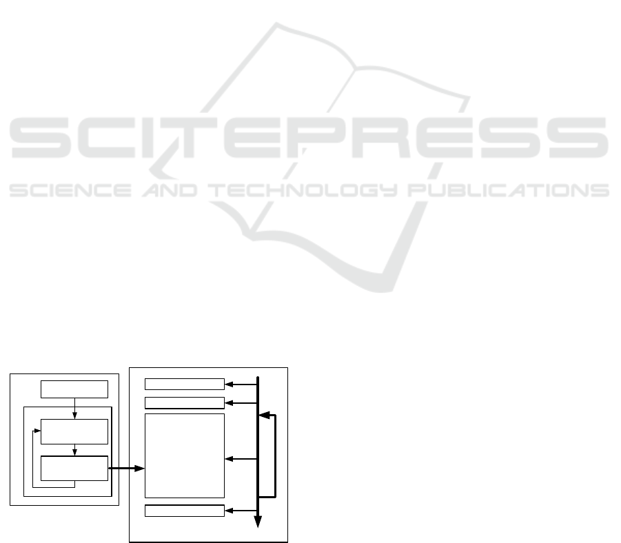
block. The concept of system is Figure 1. In the DAQ
system, the microcontroller board sends the acquired
data to PC through unidirectional communication. An
ideal DAQ system should have no data missing, can
acquire multiple data which are not of the same type
at different sample rates. The proposed system com-
PC (Simulink user defined function)
Model initialize()
Model Start()
Model Output()
Model Terminate()
Simulink
Engine
End Simulation
HW initialization
HW loop
Task except
data transmission
data transmission
u- controller
Periodic loop
Figure 1: The conceptual diagram of the proposed DAQ
system.
bines the acquired data and the next data with the in-
formation of the data type and the channel number by
using separator, and sends it to PC. Through this pro-
cess, the distinction of the series data become clear,
access time of the DAQ device to a PC decreases, and
the DAQ system can transmit the acquired data with-
out missing. Therefore, the DAQ system should sat-
isfy the following conditions.
1. The DAQ system can acquire multiple data at
different sample rates.
2. All the channels should be able to have another
type of data.
3. There is no need to match the sampling time
and the data transmission interval.
4. The block returns the data corresponding to
sampling each a period of sampling.
5. Receiving and converting data is executed at
least in Simulink.
For this conditions, we proposefollowingprotocol
and the method that generates a data packet and the
algorithm for receiving data, and implement the DAQ
block using user-defined Simulink block.
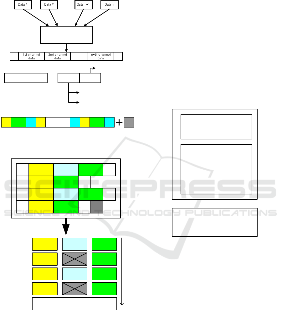
2.1 Protocol
In protocol configuration, the protocol including en-
coding changes the raw data and lengthens the to-
tal length of data, and increases the data transmis-
sion load. But, we can use some values that are not
appeared after encoding as a control command, and
the control commands make clear the data transmis-
sion. The proposed protocol is based on hex encod-
ing, and is represented in Figure 2(a). The sensed data
are changed through hex encoding and reconstructed
by adding the information of the data type and the
channel number. In hex encoding, the encoded data
are represented only as a hexadecimal number, other
numbers can be used to command. We use the ’T’,
’Q’ as the control command by inserting the ’T’, ’Q
in the front and rear of the encoded data. The ’T’,’Q’
which are used as a separator separate the data that
are sampled at different time like Figure 2(b). We add
a ’Z’ at the end of the combined the data as a termi-
nator, and use it as a data packet. If the data packet
is transmitted, as shown in Figure 3, each data can
be distinguished by the acquired sampling time us-
ing the ’T’ and ’Q’. The data between ’T’ and ’Q’
have the information about type and channel, even
some channel data are not sampled at specific sam-
pling time, the receiving part know which data are
transmitted and are not transmitted. If these functions
can be implemented as user-defined Simulink block,
system doesn’t have problem from different sampling
time.
Development of a Cost-effective Data Acquisition System using an Open-source Hardware and Matlab/Simulink
485
Info.
Data k
Hex
Data k
MSB 4 bit
type of data
LSB 4 bit
number of data
Hex encoded data
k-th channel data
=
...
......
...
Hex encoding
& framing data
...
Q
T
(a)
T
T1 data
Q T Q T
Tn data
Q Z
...
(b)
Figure 2: (a) : Hex encoding and data framing, (b) : Data
packet.
T
1st channel
data 1
2nd channel
data 1
T
3rd channel
data 1
Q
1st channel
data 2
3rd channel
data 2
Q
T
1st channel
data 3
2nd channel
data 2
3rd channel
data 3
Q
T
1st channel
data 4
3rd channel
data 4
Q Z
T1 data
1st channel
data 1
2nd channel
data 1
3rd channel
data 1
1st channel
data 2
3rd channel
data 2
1st channel
data 3
2nd channel
data 2
3rd channel
data 3
1st channel
data 4
3rd channel
data 4
T2 data
T3 data
T4 data
Get new packet from device
Figure 3: Decoding of a data packet.
2.2 DAQ Device Firmware
Generally, a DAQ system can be used through the
simple GUI format. However, the proposed system
dose not target a specific microcontroller, it is hard to
develop the system that only uses GUI format. So, for
simplifying implementation of the system, we con-
figure the DAQ device firmware as a header file for-
mat. Figure 4 represents overview of the firmware.
At start, the DAQ device connects acquired data vari-
ables and the information of the channel number and
the data type using the defined function in header file.
After the loop beginning, the DAQ device calls the
function for updating flags that represent new data
are sensed. When every data are updated, the device
calls another function for making the data packet and
sending packet to PC. As with the previous process, if
firmware is configured in the header file format for the
function declaration and the data transmission, we can
implement the DAQ system without the consideration
of hardware and protocol in the stage of use. The user
can use the system by programming like Figure 5.
u- controller firmware
connectData(1,unsigned int,data_1);
connectData(2,float ,data_2);
connectData(n,double,data_n);
SetBit(UpdateDoneFlag,1);
SetBit(UpdataDoneFlag,2);
SetBit(UpdataDoneFlag,n);
ProcessToHostBlock();
...
Initialize()
.........
loop()
connectData(channel,data_type,data_name);
SetBit(UpdateDoneFlag,channel_num);
ProcessToHostBlock();
Data transmission header file
Figure 4: The overview of firmware.
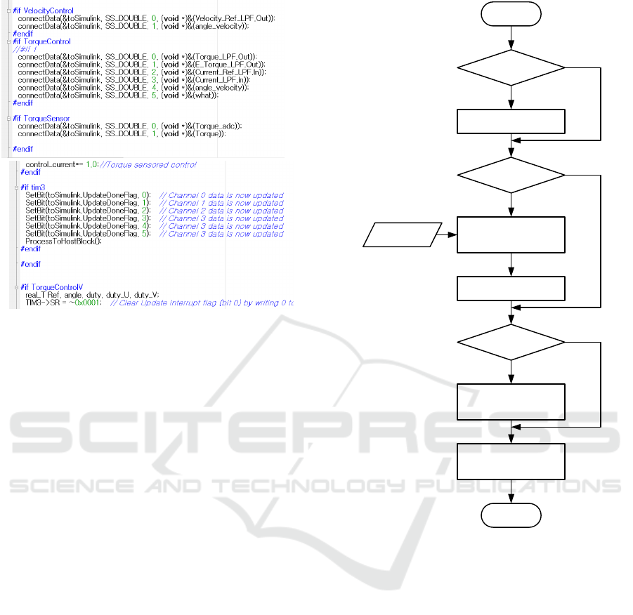
2.3 Algorithm for Block
Implementation
Figure 6 represents the flowchart of each user-defined
Simulink block. The algorithm of the block is sat-
isfying previous conditions. First branch uses the
StartFlag that is used for checking the first loop of
system as a condition of branching, this case is exe-
cuted only once for the data acquiring process. If the
StartFlag is true, communication initializing function
is run for receiving the data from the device and the
StartFlag becomes false. Second branch is used to
check block’s process operating number and the re-
maining data to decoding through the OrderIndex and
the NoDataFlag. The OrderIndex is execution num-
ber of block in Simulink, and The NoDataFlag is true
when non-decoded data packet is not exist. When the
NoDataFlag is true and OrderIndex is zero, second
ICINCO 2016 - 13th International Conference on Informatics in Control, Automation and Robotics
486
(a)
(b)
Figure 5: Examples of actual use( (a) : initialize, (b) : loop).
branch goes to yes, and block receive the packet like
Figure 2(b) from buffer. Before the received packet
are entirely decoded, the NoDataFlag is false every
loop, so second branch goes to no. Third branch goes
to yes when the block’s OrderIndex is zero. If third
branch goes to yes, the part of the data packet is de-
coded. At the end of the flowchart, the decoded data
are came out from the block refer to the channel num-
ber step by step. By the previous process, the system
can minimize the number of data receiving and decod-
ing. Because the data packet can be separated using
the ’T’ and ’Q’ like Figure 3, the algorithm can be
implement corresponding to the previous conditions.
Generating and transmitting data packet make delay
between the target system and the acquired data, but
reduce the load from device access.
2.4 Implementation of Communication
Block
We configure the communication block using the pro-
posed algorithm, communication protocol and Mat-
lab/Simulink c-code S-function. Simulink determines
priority number of every block that consist of model
according to defined rule, and the individual block’s
initialization and output calculation is executed in ac-
cordance with the priority. In consideration of the
characteristics of Simulink, the method considering
the priority should be included. For making user-
defined Simulink block, we use provided the format
about input-output size, sampling time etc, and im-
Start
StartFlag == true
InitCommunic ation()
StartFlag == false
OrderIndx == 0 &
NoDataFlag == true
Data acquisition
from u- controller
& Put data into buffer
NoDataFlag = false
OrderIndx == 0
Data decoding from buffer
Make every channel data
Update data
refer to channel number
Return
No
No
No
Yes
Yes
Yes
Data packet
Figure 6: The flowchart of the user defined block.
plement block including the method that can receive
channel number and sampling time. We configure
the block that can be connected with the USB device
driver through the function that OS provides. Also,
like Figure 7, we make the function parameter that
can be easily changed using GUI.
3 PERFORMANCE TEST
We compare the performance of proposed sys-
tem with that of DAQ system provided in Mat-
lab/Simulink Instrument Control Toolbox. We used
an open-source hardware Arch Max as a DAQ unit
for the test. The Arch Max has the features that it is
supported by mbed project based on ARM and open-
source project, the user of the Arch Max can use free
development tool via the internet, and it support drag
and drop programming. The Arch Max use the mi-
Development of a Cost-effective Data Acquisition System using an Open-source Hardware and Matlab/Simulink
487
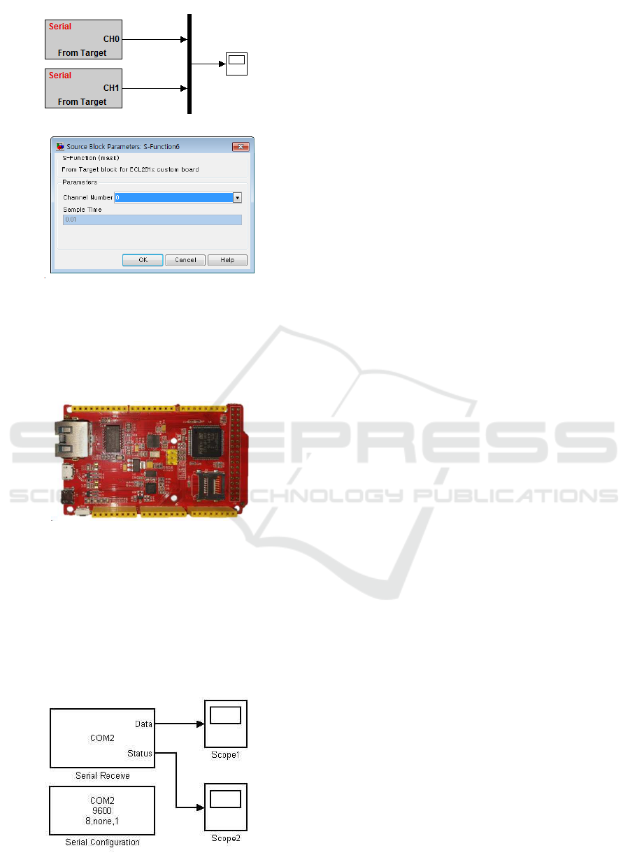
Figure 7: The implemented block and block’s GUI.
crocontroller STM32F407 that is ARM Cortex-M4,
32bit,and 168MHz maximum clock speed and sup-
port USB full speed and USB High speed. In this test,
we set clock speed 168MHz and use USB full speed
using CDC class.
Figure 8: The open-source hardware Arch Max(ARM
STM32F407).
3.1 Compare Data Packet Generation
As shown in Figure 9, the DAQ system consists of
serial communication block in the Matlab/Simulink
Instrument Control Toolbox. This system uses the
binary data transmission protocol adding terminator,
and some settings can be changed via the GUI. And
Figure 9: The DAQ system using the Matlab/Simulink In-
strument Control Toolbox.
the other system that we proposed uses the protocol
as shown in Figure 3.
We check the load of the packet generation and
transmission through measuring the time taken. If
the time taken of the packet generation gets longer,
it will have implications on the performance of the
DAQ system. Figure 10 shows the time taken that
changes from 5 floating point data to the data packet
and transmits. If we ignore the GPIO toggling time,
we can measure the time taken using the GPIO toggle
back and forth of the packet generation and transmis-
sion. In the binary data transmission case, it takes
about 1 micro-second. In the presented protocol case,
periodically, the time taken appears longer than oth-
ers because the system collects several sampled data
and periodically changes from the acquired data to the
packet. So, we measure the longest time and that is
about 8 micro-second. If we use a 1kHz sampling
rate, the time taken of both cases are not over 1% of
the available time. So the packet generation problems
are hardly happen.
3.2 DAQ Performance Test
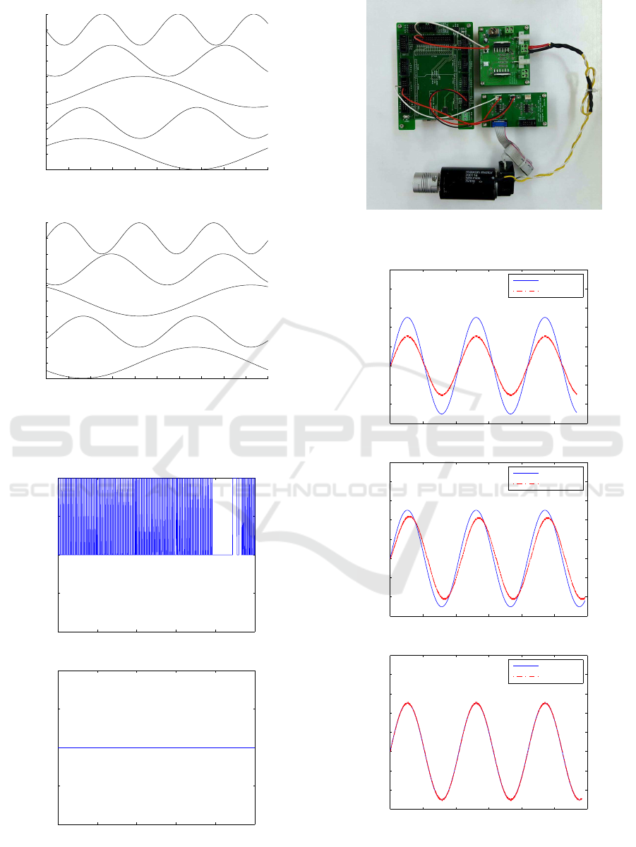
Figure 11 represents the result of receiving 5 float-
ing point data about 100Hz sampling and 1000Hz
sampling through Matlab/Simulink Instrument Con-
trol Toolbox. The results have data missing, and re-
sult of 100Hz sampling frequency shows indentation
because of low sampling frequency. The result of
1000Hz sampling frequency has better smoothness
than previous case, but it’s data missing is longer
than the previous. Figure 12 is the results of receiv-
ing 5 floating point data using proposed system about
1000Hz sampling and 5000Hz sampling. The ex-
periment results doesn’t have the data missing both
1000Hz sampling and 5000Hz sampling. Depending
on the experiment results, the proposed system has
more better data acquisition ability than that of Mat-
lab/Simulink Instrument Control Toolbox.
Figure 13 is the visualized data drop. The method
which measures the data drop is sending the inte-
ger data that is increased 1 per sampling with other
data and checks the difference of adjacent two num-
bers. If the difference is n, then n− 1 sampled data
are dropped. In Figure 13, the case that uses Mat-
lab/Simulink library shows 242 data drop when block
receive data 1kHz. This means 242 data drop per
1.242 second, so the data drop rate is about 19.5%. In
contrast, the result of the proposed system shows no
data drop even sampling frequency is 10 times faster.
In repeated experiments, about 20% data drop happen
when Matlab/Simulink library is used, and data drop
doesn’t happen when the presented system is used.
ICINCO 2016 - 13th International Conference on Informatics in Control, Automation and Robotics
488
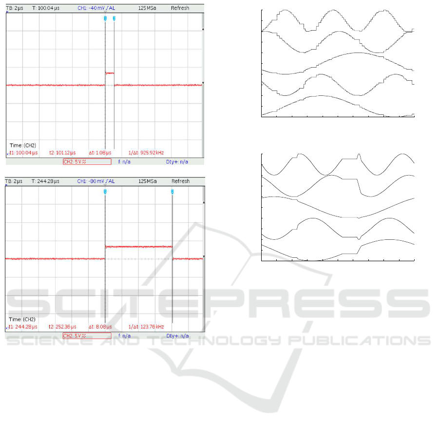
(a) Binary data transmission packet case.
(b) User-defined data transmission packet case.
Figure 10: Time taken to generate a packet of 5 floating
point data.
3.3 Actual DAQ System Test with DC
Motor Velocity Control
Figure 14 represents the configuration of DC motor
experimental system for the practical application of
the proposed system. The experimental system con-
sists of the DC motor, the encoder board, the motor
driver board and the Arch Max with the Arch Max
adaptation board.
The experiment is to control the angular velocity
of DC motor in no-load condition. We configure the
PI controller. In the experiment, we give the sinu-
soidal reference to system, sample angular velocity
1000Hz sampling frequency and configure the feed-
back loop. At the same time, we configure the mon-
itoring system using Matlab/Simulink scope block.
With reference to the plot in Figure 15, the user can
easily design the PI controller by changing the coeffi-
cients.
0 0.1 0.2 0.3 0.4 0.5 0.6 0.7 0.8 0.9 1
−1
0
1
2
3
4
5
6
7
8
9
DAQ result of 5 sinusoidal signals (100Hz)
time
Amp(offset : 0, 2, 4, 6, 8)
(a)
0 0.1 0.2 0.3 0.4 0.5 0.6 0.7 0.8 0.9 1
−1
0
1
2
3
4
5
6
7
8
9
DAQ result of 5 sinusoidal signals (1000Hz)
time
Amp(offset : 0, 2, 4, 6, 8)
(b)
Figure 11: The result of the Simulink library block( (a) :
100Hz sampling, (b) : 1000Hz sampling).
4 CONCLUSIONS
In this paper, we proposed a new cost-effective data
acquisition system using open-source hardware and
Matlab/Simulink. The proposed DAQ system has the
following features : it uses an open-source microcon-
troller board that supports USB communication or se-
rial communication, it is implemented for use with
Matlab/Simulink so that one can utilize all the con-
venient functions provided by Matlab/Simulink. To
implement the proposed system, we used an open-
source hardware Arch Max as a DAQ unit, developed
the device firmware and a DAQ block using user-
defined c-code S-function. The firmware is in the
form of a header file, which includes several handy
functions. One can program the data acquisition by
calling the provided functions in a well defined se-
quence. One can configure the developed Simulink
block so that he can obtain multiple data at differ-
ent rates by changing GUI parameters appropriately.
Throughthe experiment, we showed that the proposed
DAQ system has better performance than the system
provided by Matlab/Simulink. In addition to the ac-
quisition of sensor data, the proposed DAQ system
Development of a Cost-effective Data Acquisition System using an Open-source Hardware and Matlab/Simulink
489
0 0.1 0.2 0.3 0.4 0.5 0.6 0.7 0.8 0.9 1
−1
0
1
2
3
4
5
6
7
8
9
DAQ result of 5 sinusoidal signals (1000Hz)
time
Amp(offset : 0, 2, 4, 6, 8)
(a)
0 0.1 0.2 0.3 0.4 0.5 0.6 0.7 0.8 0.9 1
−1
0
1
2
3
4
5
6
7
8
9
DAQ result of 5 sinusoidal signals (5000Hz)
time
Amp(offset : 0, 2, 4, 6, 8)
(b)
Figure 12: The result of the presented user defined function
block( (a) : 1kHz sampling, (b) : 5kHz sampling).
0 0.2 0.4 0.6 0.8 1
0
0.5
1
1.5
2
time
drop rate check(1kHz, Matlab library block)
0 0.2 0.4 0.6 0.8 1
0
0.5
1
1.5
2
time
drop rate check(10kHz, User defined function block)
Figure 13: Visualized data drop.
Figure 14: The experiment setup of the DAQ system for DC
motor control.
0 1 2 3 4 5 6
−150
−100
−50
0
50
100
150
200
250
time
Kp = 0.1, Ki = 0
Ref. signal
velocity
0 1 2 3 4 5 6
−150
−100
−50
0
50
100
150
200
250
time
Kp = 0.1, Ki = 1
Ref. signal
velocity
0 1 2 3 4 5 6
−150
−100
−50
0
50
100
150
200
250
time
Kp = 0.1, Ki = 15
Ref. signal
velocity
Figure 15: Experiment results of DC motor PI velocity con-
trol(Top : Kp = 0.1 , Ki = 0 Middle : Kp = 0.1, Ki = 1
Bottom : Kp = 0.1, Ki = 15).
ICINCO 2016 - 13th International Conference on Informatics in Control, Automation and Robotics
490

can be used to monitor all the variables in the con-
trol algorithm. This allows the user to have better in-
sight in designing control system by providing plen-
tiful information. This aspect was clearly illustrated
by the controller design example. Since the proposed
system is based on open-source hardware, it is more
cost-effective than existing DAQ systems using PCIe
or expensive DAQ boards. The proposed system can
be successfully used for teaching purpose in under-
graduate or graduate courses.
ACKNOWLEDGEMENTS
This research was supported by the MSIP(Ministry
of Science, ICT and Future Planning), Korea, under
the ITRC(Information Technology Research Center)
support program (IITP-2016-H8601-16-1003) super-
vised by the IITP(Institute for Information & commu-
nications Technology Promotion)
REFERENCES
ABU HASAN, R. (2012). Development of USB Biosignal
DAQ System with Matlab Interface. PhD thesis, Uni-
versiti Teknologi Malaysia.
Claros-Marfil, L. J., Padial, J. F., and Lauret, B. (2016). A
new and inexpensive open source data acquisition and
controller for solar research: Application to a water-
flow glazing. Renewable Energy, 92:450–461.
Khan, F. A., Hafeez, Z., Mirza, A., and Ain, Q.-u. (2011).
Design of fpga based daq card using pci express pro-
tocol. In Multitopic Conference (INMIC), 2011 IEEE
14th International, pages 211–216. IEEE.
Lee, Y.-S., Yang, J.-H., Kim, S.-Y., Kim, W.-S., and Kwon,
O.-K. (2012). Development of a rapid control proto-
typing system based on matlab and usb daq boards.
Journal of Institute of Control, Robotics and Systems,
18(10):912–920.
Mandal, S., Sau, S., Chakrabarti, A., Saini, J., Pal, S. K.,
and Chattopadhyay, S. (2015). Fpga based novel high
speed daq system design with error correction. In
VLSI (ISVLSI), 2015 IEEE Computer Society Annual
Symposium on, pages 80–85. IEEE.
MathWorks, I. (2009). Matlab & simulink instrument con-
trol toolbox. Neural Network Toolbox. The Math-
Works Inc.
Pearce, J. M. (2015). Commentary: Open-source hardware
for research and education.
Pearce, J. M. et al. (2012). Building research equip-
ment with free, open-source hardware. Science,
337(6100):1303–1304.
Pereira, R., Sousa, J., Fernandes, A., Patr´ıcio, F., Carvalho,
B., Neto, A., Varandas, C., Gorini, G., Tardocchi, M.,
Gin, D., et al. (2008). Atca data acquisition system
for gamma-ray spectrometry. Fusion engineering and
design, 83(2):341–345.
Proffitt, J., Hammond, W., Majewski, S., Popov, V., Rayl-
man, R., and Weisenberger, A. G. (2006). Imple-
mentation of a high-rate usb data acquisition system
for pet and spect imaging. In Nuclear Science Sym-
posium Conference Record, 2006. IEEE, volume 5,
pages 3063–3067. IEEE.
Salami, M.-J. E., Tijani, I., and Jibia, A. U. (2011). De-
velopment of real-time software interface for multi-
component transient signal analysis using labview and
matlab. In Mechatronics (ICOM), 2011 4th Interna-
tional Conference On, pages 1–5. IEEE.
Stankovi´c, M., Manojlovi´c, S., and Jovanovi´c, Z. (2012).
Acquisition system for analysis and design of elec-
trical servo system based on usb daq card dt9812.
FACTA UNIVERSITATIS, Series: Automatic Control
and Robotics, 11:69–79.
Storey, B. D. (2002). Using the matlab data acquisition
toolbox. URL: http://faculty.olin.edu/bstorey/Notes/
Card. pdf (accessed January 2008).
Development of a Cost-effective Data Acquisition System using an Open-source Hardware and Matlab/Simulink
491
