
Exploiting Web Technologies to Connect Business Process Management
and Engineering
Dario Campagna, Stefano Costanzo, Carlos Kavka and Alessandro Turco
ESTECO SpA, Area Science Park, Padriciano 99, Trieste, Italy
Keywords:
Business Process Modeling, Business Process Execution, Decision Support Systems.
Abstract:
The Business Process Model and Notation (BPMN) standard can be used for representing low-level simulation
and automation workflows for scientific, engineering and manufacturing processes. This paper focuses on
removing the main obstacles that limit a more widespread adoption of the standard and the related technology:
collaboration and data management. Web technologies can provide the necessary complementary features to
the BPMN editing and execution activities: real-time collaboration, accessibility, information and expertise
sharing. The proposed prototype mimics a SaaS (Software-as-a-Service) platform offering public community
support and a private working area which can be shared in real-time with other users. The prototype includes
an execution engine the implementation of which has been tailored to support the data structures required by
scientific and engineering applications. The ideas presented in this paper are supported by three use cases:
a Multi Disciplinary Optimization case (which is a typical engineering-domain problem involving the design
of complex items), a collaborative decision-making scenario (the negotiation process for generating a lecture
timetable at a university) and Lego-like decomposition of an optimization algorithm (its constituent elements
can be easily re-assembled and shared with our platform).
1 INTRODUCTION
The community working on Business Processes (BPs)
has been very successful in defining standards and
made significant efforts to encourage their widespread
use. In particular, the Object Management Group
(OMG) defined the Business Processing Model and
Notation (BPMN) (OMG, 2011) standard which has
become the de-facto standard in the field. It couples
an expressive workflow graphical representation with
a rigorous XML encoding of processes and interac-
tions among them. However, in the engineering de-
sign domain the situation is quite different. Since
no common accepted standard has been formally de-
fined, the existing software tools managing simula-
tion and design workflows use their own proprietary
formats. This certainly limits the collaboration possi-
bilities of engineering teams and the exchange of data
between tools.
In our experience the use of process workflows
in engineering imposes certain requirements which
are not always present in the general business pro-
cess arena. Specifically they are: (1) the handling
of very large files which are generated by Computer
Aided Design (CAD) or Computed Aided Engineer-
ing (CAE) software, (2) the need for a sandbox-
based execution to protect the system from the con-
sequences of wrongly defined tasks or scripts and (3)
a strong persistence enabling the workflow execution
to be interrupted and resumed later and avoid losing
the results of very long computations (may be months
of computation time).
Not less important are the collaboration require-
ments which are nowadays absolutely essential. In
fact, globalization, web technologies and increasing
product complexity have resulted in companies radi-
cally changing their approach to product design and
process development. Larger, geographically dis-
tributed design teams specialized in different disci-
plines should collaborate to get the job done. The
market demands for collaborative solutions capable
of bringing the global design teams together in a se-
cure web-based virtual environment that enables en-
gineering teams to collaborate effectively across ge-
ographies and business units.
Assuming that the BPMN standard is sufficiently
rich to model engineering and scientific processes, as
shown in (Comin et al., 2013) and (Campagna et al.,
2015), and that the existing BPMN software is not
suitable for that kind of applications (see Section 2),
186
Campagna, D., Costanzo, S., Kavka, C. and Turco, A.
Exploiting Web Technologies to Connect Business Process Management and Engineering.
DOI: 10.5220/0005978901860193
In Proceedings of the 11th International Joint Conference on Software Technologies (ICSOFT 2016) - Volume 1: ICSOFT-EA, pages 186-193
ISBN: 978-989-758-194-6
Copyright
c
2016 by SCITEPRESS – Science and Technology Publications, Lda. All rights reserved

the issue addressed in this paper is whether a tailored
implementation could indeed solve the problem. Such
a solution would bring to the engineering community
the advantages of standardized process modeling en-
suring interoperability and improving collaboration.
Our proposal is a Software-as-a-Service (SaaS)
prototype BPMN platform based on Web technolo-
gies which can provide the necessary complementary
features to both editing and execution activities: real-
time collaboration, accessibility, information and ex-
pertise sharing. The proposed prototype platform of-
fers public community support and a private working
area which can be shared among users. We expect this
paper to contribute to changing the way scientific, en-
gineering and manufacturing processes are modeled
with an innovative approach.
Section 2 starts with a presentation of the related
work. Section 3 introduces the SaaS prototype plat-
form with details on the editor and engine function-
alities. Section 4 describes three uses cases imple-
mented in terms of the SaaS platform and Section
5 presents future developments and the final conclu-
sions.
2 RELATED WORK
BPMN 2.0 is a standard for the representation of
business processes supported by a wide community
and pushing its portability among platforms. BPMN
2.0 can be used to formally build scientific work-
flows in the context of optimization processes both
in terms of process representation and execution, as
presented in (Comin et al., 2013). Moreover, the au-
thors in (Campagna et al., 2015) have shown how to
take advantage of the BPMN 2.0 extensibility mech-
anism to support the modeling and the execution of
engineering processes.
A number of desktop and web applications sup-
porting BPMN 2.0 are available. For example, Ca-
munda (Camunda, 2014), Trisotech BPMN Mod-
eler (Trisotech, 2015), Yaoqiang (Yaoqiang Inc.,
2009), GenMyModel (GenMyModel, 2013), Sig-
navio Process Editor (Signavio GmbH, 2013), Sig-
navio Workflow (Signavio GmbH, 2016), Activ-
iti (Alfresco, 2013) and so forth, just to name a few.
As regards workflow editing, these applications dif-
fer in the degree of compliance to the standard, the
number of BPMN 2.0 elements available for work-
flow editing and the implemented collaborative fea-
tures (if any). While there are more than 20 applica-
tions supporting BPMN 2.0 workflow editing (OMG,
2016), only some of them support workflow execu-
tion. Activiti, Camunda and Signavio Workflow are
among those.
Activiti is a lightweight workflow and Business
Process Management (BPM) platform which offers a
set of components that can be combined to form the
desired solution for BPM. The Activiti Modeler Com-
ponent allows users to create BPMN 2.0 workflows,
but it does not have any collaborative out-of-the-box
features and does not support certain BPMN 2.0 arti-
facts, e.g., Data Objects, Data Inputs, Data Outputs.
The Activiti Engine component is a process engine
that natively runs BPMN 2.0 processes, it allows users
to create custom activity types but does not offer sand-
boxes for task execution.
Camunda is an open source platform for the work-
flow and BPM creation. Its workflow editor charac-
teristics and capabilities are similar to those of Activ-
iti Modeler. The Camunda execution engine does not
execute tasks in sandboxes, but supports the execution
of service tasks as external tasks.
Signavio Workflow is a cloud-based workflow
management platform. Lightweight business process
models can be quickly and easily created with its
built-in web-based process builder. However, the pro-
cess builder does not offer collaborative editing fea-
tures.
To the best of our knowledge none of the currently
available applications satisfies the engineering and
collaboration requirements described in Section 1.
3 SaaS PROTOTYPE
To show the effectiveness of the BPMN language
for the representation of low-level simulation and au-
tomation workflows we created a prototype which
mimics a Software-as-a-Service (SaaS) platform. The
platform is an Extreme Collaboration environment
(Kim et al., 2010) where users can model their pro-
cesses, share them with co-workers and launch and
monitor their executions. It is composed of: (1) a web
application for editing and managing BPMN work-
flows and (2) an engine for workflow orchestration
and task execution.
Compared to Activiti, Camunda and Signavio
Workflow, our platform supports modeling and exe-
cution of less BPMN 2.0 elements. It also lacks some
advanced features such as the role-based access and
execution data analysis functionalities of Camunda.
Nevertheless, our platform has characteristics that are
crucial for the satisfaction of the requirements listed
in Section 1 that similar tools lack. These require-
ments are satisfied owing to the chosen architecture
and technologies. The web application has a number
of collaborative features enabled by its client-server
Exploiting Web Technologies to Connect Business Process Management and Engineering
187
architecture and use of Web technologies. The en-
gine, inspired by enterprise architecture systems, en-
ables sandbox-based task executions and a strong per-
sistence. Data transfer is reduced during workflow
runs due to the use of Uniform Resource Identifiers
(URI) for identifying and referencing files.
Our prototype supports a limited number of ar-
tifacts which nonetheless are sufficient for complex
process modeling. The chosen elements are: Start
Event, End Event, User Task, Script Task, Parallel and
Exclusive Gateway, Data Object.
Exclusive Gateways, Script Tasks and User Tasks
consume and produce data. The current implementa-
tion of the prototype exploits the default value BPMN
2.0 extensions introduced in (Campagna et al., 2015).
It uses simple types (long, float, string and boolean)
and multidimensional arrays built with them to repre-
sent data values. Script and User Tasks often require
support files for their execution or, equivalently, their
output is extracted with a file. Our SaaS platform has
an ad hoc section for storing, organizing and sharing
files. These resources can be accessed at editing time
(e.g. by assigning a URI for file identification to a
Data Object value) and at runtime, while resources
produced as output are made available as soon as they
are processed by the BPMN engine.
3.1 Web Application
The web application enables users to create BPMN
workflows, request and monitor their executions, per-
form assigned User Tasks and manage files. It is char-
acterized by a set of collaborative features. Team-
work is enabled in different ways: by inviting peo-
ple to collaborate on projects, sharing processes, tem-
plates and files, simultaneously editing a workflow,
assigning and performing User Tasks within groups
and importing and exporting BPMN files. The web
application has six sections, namely: the BPMN edi-
tor, the file management section, the administration
panel, the run dashboard, the user task dashboard
and the public section.
3.1.1 Features
In this sub-section we will describe a possible “user
journey” through the web application. The user starts
by creating a new workflow with the BPMN editor
and uploading the necessary files in the file manage-
ment section. As soon as a first draft of the workflow
is ready the user creates a working group from the
administration panel (new participants are notified by
e-mail). The uploaded files can now be shared from
the file management section directly with single users
or the entire group. Workflows can be shared in the
Relational
Database
NoSQL
Database
Web Browser
WebSocket
endpoint
REST
endpoints
Editor service
User task
service
Engine
service
Client
side
Server
side
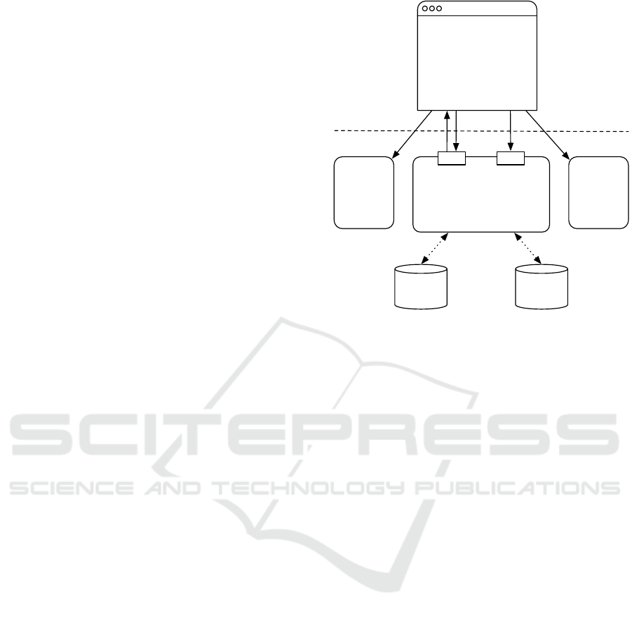
Figure 1: Web application architecture. Straight lines rep-
resent communication over HTTP, while dotted lines repre-
sent database read/write operations.
same way from the BPMN editor. Once the workflow
is shared with the group any of its members can edit
it. Multiple users can simultaneously visualize and
modify the workflow in real-time. When the work-
flow editing is complete, the user requests a run on
the run dashboard and monitors it. Any group mem-
ber can be the assignee of a User Task and will re-
ceive a notification when the running process triggers
it. Incoming User Tasks are shown on the user task
dashboard, which has a clear interface showing the
data provided to execute the task and data required
for marking the task as complete. Once the run has
terminated the user can retrieve the workflow output
data from the run dashboard.
As said above, workflows can be shared with sin-
gle users or user groups. The web application public
section enables a different kind of workflow sharing.
It basically works like a blog: a user can publish a post
and embed a workflow in it so anyone with the access
to the web application can explore its public section
content. Other web application users can add com-
ments to posts and use published workflows as build-
ing blocks for their own workflows (for example, a
user can create a new workflow using a published one
as template).
3.1.2 Client-server Architecture
The web application has a simple client-server archi-
tecture as shown in Figure 1. On the server side we
have three services implemented using Java EE 7 (Or-
ICSOFT-EA 2016 - 11th International Conference on Software Engineering and Applications
188
acle, 2013). On the client side we have an Angu-
larJS (Google, 2010) single page application (SPA)
accessible via any web browser.
The editor service is a lightweight service with a
set of Representational State Transfer (REST) end-
points and a WebSocket endpoint. The latter is the
key enabler of the simultaneous real-time workflow
visualization and editing. The editor service manages
workflow persistence, file storage and retrieval, user
data and user groups. It is not based on a complex
business logic, i.e. the logic behind the editing of
BPMN workflows. User and group data are stored
in a relational database, whereas workflows and files
are stored in a NoSQL database .
The entire web application business logic resides
within the SPA. It fetches and stores user and work-
flow data via the editor service while autonomously
managing the view and the logic of the six different
sections that constitute the web application. More-
over, the SPA exploits the engine service for manag-
ing workflow runs and the user task service for deal-
ing with User Tasks. Both the engine service and the
user task service are lightweight services with REST
and WebSocket endpoints.
3.2 BPMN Engine
The BPMN engine manages workflow orchestration
and execution of Script and User Tasks. Its imple-
mentation is focused on reliability. It must guaran-
tee the persistence of the computed data and preserve
the execution status in case of accidental and/or unex-
pected blackouts. Moreover, since Script Tasks could
contain dangerous code special execution sandboxes
have been provided.
The architecture of the engine is inspired by enter-
prise system architectures and uses a queuing system
to decouple its components. The transactionality is
guaranteed by a convenient access to the database in
which data is stored.
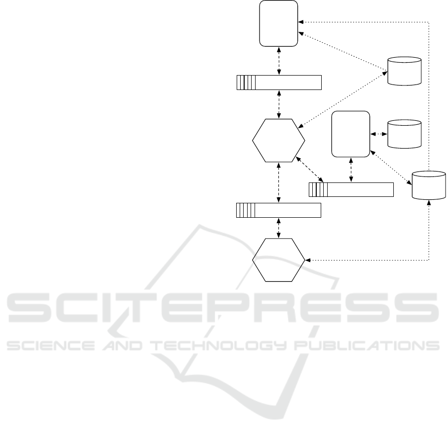
Figure 2 shows the platform engine architec-
ture. Its nucleus is the so called engine core, which
is a Java SE 8 (Oracle, 2014) application using
Camel (Apache, 2004), a versatile open-source inte-
gration framework based on known enterprise inte-
gration patterns (Hohpe and Woolf, 2003). The en-
gine core receives requests for workflow executions
from the engine service, introduced in Section 3.1.2,
through a Java Message Service (JMS) (Java Commu-
nity Process, 2003) queue. Given the XML represen-
tation of a BPMN workflow, the engine core executes
workflows in an event-based fashion. The execution
of each BPMN element and the execution of the work-
flow are considered events. The engine core uses dif-
User task
service
Engine
service
Engine JMS Queues
Engine
Core
JavaScript
Evaluator
User tasks JMS Queues
Script tasks JMS Queues
Run
Database
File
Database
User task
Database
Figure 2: BPMN engine architecture. Dashed lines rep-
resent send/receive operations to/from JMS queues, while
dotted lines represent database read/write operations.
ferent enterprise integration patterns to process these
events. For example, the splitter pattern is used to
implement the Parallel Gateway behavior, while the
content-based router pattern is used to route events
based on the type of element they are related to. The
engine core achieves execution data persistence ow-
ing to a relational database (i.e., the run database in
Figure 2).
The engine core delegates the execution of Script
Tasks and User Tasks to two other components, the
user task service, introduced in Section 3.1.2, and
the JavaScript evaluator (currently the only supported
scripting language for Script Tasks is JavaScript).
These components communicate with the engine core
via JMS messages. The user task service notifies
users of incoming User Tasks and conveys the com-
pletion of User Tasks to the engine. User Task
execution information are kept persistent in a rela-
tional database (i.e. the user task database in Fig-
ure 2). The JavaScript evaluator is a Java 8 applica-
tion which receives a script and input data required by
the script, runs the script with the Nashorn JavaScript
engine (Ponge, 2014) and conveys the computed re-
sults back to the engine core. Both the user task
service and the JavaScript evaluator access the file
database, a NoSQL database used for file storage
Exploiting Web Technologies to Connect Business Process Management and Engineering
189

Figure 3: Individual Discipline Feasible approach for a MDO problem with two disciplines.
and retrieval. The decoupling of the task execution
from the workflow orchestration has two main advan-
tages. Firstly, task execution is asynchronous, hence
true parallelization of tasks is possible and the engine
core does not have to wait idle for task completion.
Secondly, being the task execution sandboxed, the
engine core is protected from potentially dangerous
JavaScript scripts.
File transfers are reduced during the workflow
runs owing to the use of URI for identifying and ref-
erencing files. The engine core only manages URI,
for example it transfers them to tasks when executing
data associations. Files are effectively accessed only
during task executions. When a User Task is run a
user may download existing files or upload new ones.
A JavaScript script can request a file content and store
new data in the file database.
The engine service has REST and WebSocket end-
points to request workflow executions, monitor their
status, manage their life-cycles (e.g. an ongoing run
can be stopped) and retrieving run results. Run re-
quests are forwarded to the engine core via JMS mes-
sages, whereas run information and results are re-
trieved from the run database.
To guarantee the persistence of the computed data
and preserve the execution status, the engine uses
Atomikos TransactionEssentials (Atomikos, 2016)
for managing multi-resource transactions with the
Java Transaction API (Java Community Process,
2002). Multi-resource transactions are essential for
guaranteeing reliability and robustness in a system in-
volving both JMS queue and databases. Combined
with the event-based architecture, they enable users to
restore the engine after accidental and/or unexpected
blackouts, resume not yet terminated executions and
pause ongoing executions.
4 USE CASES
We propose three use cases: a typical engineering
scenario - the composition of different studies with a
Multi Disciplinary Optimization (MDO) approach; a
high level orchestration workflow exploiting the col-
laborative features of the web prototype and a techni-
cal low-level task such as the assembly of a Genetic
Algorithm. These two latter use cases cover different
human-machine interaction scenarios. In the former
case, the interaction is part of the model which in-
cludes User Tasks, Script Tasks and Operational Re-
search algorithms. The latter case involves only Script
Tasks and the required human intervention is lim-
ited to the recombination of the process sub-elements
(fragments) which can be found in the web applica-
tion public section.
4.1 Individual Discipline Feasible MDO
Multi Disciplinary Optimization is a flourishing re-
search field and an undeniable potential for complex
engineering project applications. It is a particular
case of black-box optimization with multiple intrinsi-
cally interconnected “boxes”: some of the input vari-
ables of a black-box (usually called discipline) are
the output variables of another one and vice versa.
In industrial applications this situation occurs when
the project is decomposed in sub-systems which are
treated separately (for example, when designing a
new car, sub-systems can be the engine, the wheels,
the car body, etc.) or when different physics are stud-
ied on the same object with different simulation soft-
ware (a typical example is the interaction between
structural and fluid dynamic computations on an air-
craft wing profile). There are several mathematical
techniques for handling these kinds of problems (Ted-
ford and Martins, 2010). We present here the pro-
cess governing the Individual Discipline Feasible ap-
ICSOFT-EA 2016 - 11th International Conference on Software Engineering and Applications
190

proach modeled with our BPMN platform as shown
in Figure 3. A detailed description of the technique
is not the core topic of this paper, but the idea is that
different disciplines (two in this example) are decou-
pled using slack variables and can solved in parallel.
An optimization algorithm orchestrates a convergence
loop carrying out the original optimization task with
additional constraints to enforce the compatibility be-
tween the disciplines (i.e. slack variables have to be
equal to the corresponding real variables). Parallel
and Exclusive Gateways perfectly manage this sce-
nario, whereas Script Tasks take care of the optimiza-
tion algorithm and of the convergence check. The two
disciplines are included in a generic task shown in the
figure but depending on how they are implemented,
they can be handled with Script Tasks, Service Tasks
or User Tasks.
4.2 Collaborative Workflow
In collaboration with DIEGM, the department of the
University of Udine (Italy) which responsible for
managing lecture timetables, we modeled a realis-
tic prototype of the negotiation process and the op-
timization of the scheduling problem. Due to spa-
tial limitations the resulting workflow is not included
in the paper, but is accessible at the following link:
https://goo.gl/W9tbZu.
The process involves a negotiation phase in
which the professors declare their availability and ap-
prove/refuse the first draft of the schedule. These
communications are modeled as User Tasks (triggered
in parallel) which can be performed with our plat-
form. The Operational Research solver which gen-
erates the optimal timetable once all constraints have
been coded is also part of the process. The function
calling the solver has been pre-loaded in the Script
Task evaluator and made available through the work-
flow editor. A possible alternative would have been to
encapsulate the solver in an ad hoc task, recognized
by a BPMN extension element, but this solution is
much more complex both in terms the engine archi-
tecture and the user interaction. The secretary office
is responsible for all manual tasks that cannot be eas-
ily automated and all direct controls required by the
procedure.
The model is completely executable with the pro-
totype platform: the professors involved in the pro-
cess will receive a notification whenever they have to
provide information and the User Task interface will
show them the necessary inputs and the data types
of the requested outputs. Operational Research algo-
rithms are invoked automatically and produce output
files of the prescribed form.
4.3 Scientific Workflow
This section is focused on an alternative use of
BPMN, rather different from what we have shown so
far. It concerns the design (and the execution) of op-
timization algorithms and their scientific dissemina-
tion. One of the most interesting aspects is the pos-
sibility to model each single phase of any algorithm
and thus even reproduce algorithms described in liter-
ature. The use of the public section of the application
to post fragments or entire algorithms could consider-
ably facilitate the exchange of knowledge in the sci-
entific community.
The process representing an algorithm usually
does not include User Tasks. Instead, the engineer or
the analyst directly creates and edits the process. As
an example, we decomposed a generic purpose evolu-
tionary optimization algorithm (Goldberg, 2003) in its
main phases: Initialization, Point Generation, Evalu-
ation, Selection and Stopping Criteria. The proposed
example is a representation of a real algorithm sim-
plified so as to facilitate its understanding by hiding
the data objects and showing only the essential fea-
tures of each phase, which have been enclosed in sub-
processes to isolate them.
The inner structure of all sub-processes is clearly
visible in Figure 4. The initialization with randomly
created points is followed by the main algorithm loop,
which is enclosed between two Exclusive Gateways.
The loop starts with the generation of new tentative
solutions (points) using a random point perturbation.
Then the new points have to be evaluated to com-
pute their fitness (i.e. the level of compliance with
the optimization problem considering objectives and
constraints). If the points do not show very good fit-
ness and hence the Stopping Criteria condition is not
satisfied, the loop continues with the Selection of the
best points which will re-enter the loop.
The aim of this generalization is to enable the
modeling of as many different optimization ap-
proaches as possible by only using this simple skele-
ton. In the current example we have used Script
Tasks to code the routines and a test function well-
known in literature for the Evaluation sub-process, the
Shubert Function (Hedar, 2013). This process aims
at showing that it is possible to define the building
blocks of any optimization algorithm and freely com-
bine them. This decomposition enabled by BPMN
opens the door to optimization algorithm customiza-
tion and hybridization responding perfectly to specific
applications in a rather simple way.
A specialized Point Generation sub-process is
shown in Figure 5. It simulates the behavior of a Ge-
netic Algorithm: the incoming points are handled by
Exploiting Web Technologies to Connect Business Process Management and Engineering
191
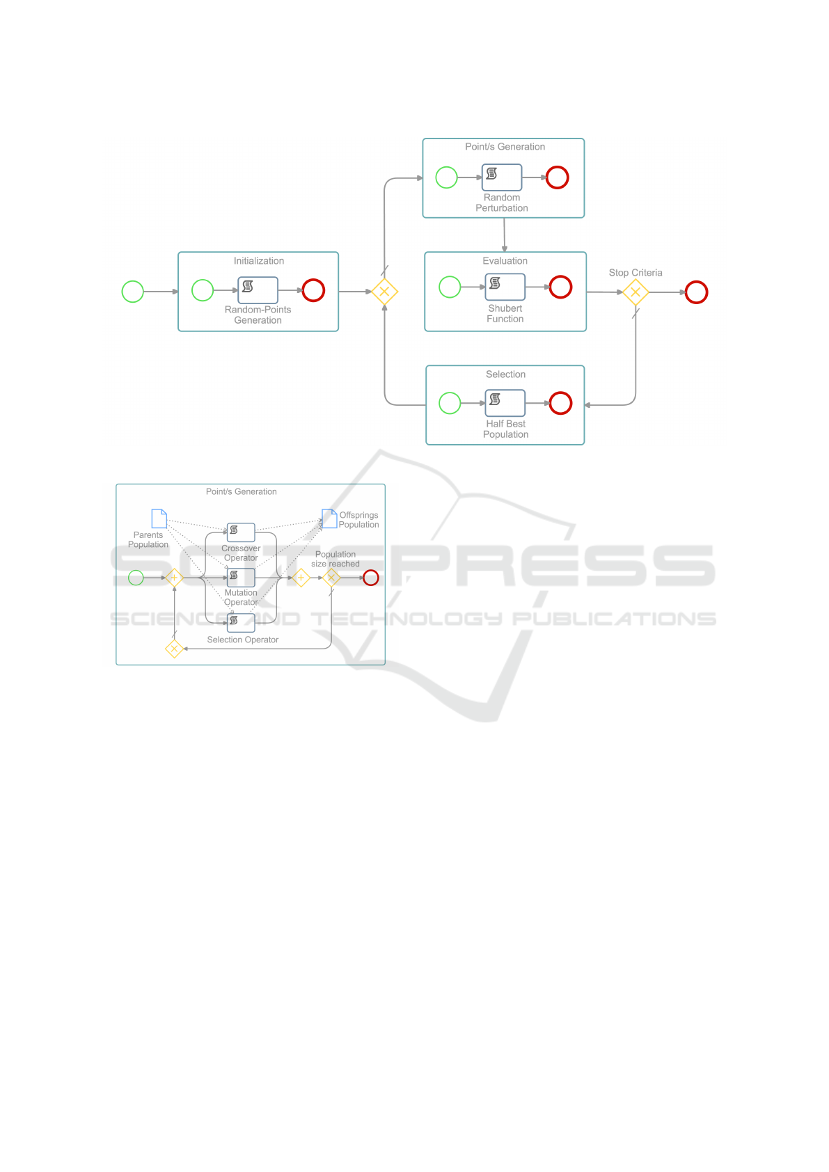
Figure 4: BPMN model of a generic Evolutionary Algorithm.
Figure 5: A possible specialization of the sub-process re-
sponsible for the generation of new configurations. In this
example we show a Genetic Algorithm with parallel opera-
tors.
separate Script Tasks (corresponding to genetic algo-
rithm operators) to generate a new set of points. The
three operators, i.e. Crossover, Mutation and Selec-
tion, are enclosed between two Parallel Gateways and
work thus concurrently. This creation block is in turn
enclosed between two Exclusive Gateways which en-
sure that the process is iterated until the required num-
ber of new points is reached.
By simply replacing the generic Point Genera-
tion sub-process in Figure 4 with this sub-process we
have obtained a complete Genetic Algorithm. This
building block recombination can be easily extended
to other processes to virtually model any algorithm
or to combine different algorithms. In this way en-
gineers can write and modify just small elements of
possibly very complex algorithms and insert them in
the overall structure, instead of re-writing the entire
process. Furthermore, these elements can be easily
shared (in the public section, for example) and hence
exchanged within the scientific community facilitat-
ing knowledge dissemination.
5 CONCLUSIONS
We described the implementation and the possible use
of a prototype SaaS platform managing BPMN edit-
ing and execution. Since it is a prototype and we plan
it to become a real service, we used the most recent
and updated technologies in its development.
The combination of the capabilities of the BPMN
standard with the collaborative features of a modern
web application enables the handling of very inter-
esting scenarios for the scientific and the engineering
community. Advanced engineering workflows can be
directly managed with BPMN, while Extreme Col-
laboration environments can be supported with Web
technologies. The public section offers the possibility
to share information and knowledge. The use cases
we presented cover these three scenarios. In light
of this, we plan to extend our prototype to include
all BPMN elements, both for the graphical modeling
with the web editor and the workflow execution with
the associated engine. Of course, compliance with the
standards will be always a top priority to facilitate and
promote the interchange of BPMN models between
different tools (OMG, 2016).
We also plan to add Functional Mockup Interface
ICSOFT-EA 2016 - 11th International Conference on Software Engineering and Applications
192

(FMI) support through a specifically dedicated task.
FMI is a well-defined standard which supports model
interchange and co-simulation of dynamic models in
engineering applications (The Modelica Association,
2010). By adding FMI support our prototype will be
able to create and execute workflows which can be
linked to third party applications supporting the stan-
dard. This will enable the use of engineering models
created with Modelica and other engineering tools as
components of BPMN workflows.
The current automation of engineering design en-
vironments has put the engineer “out of the loop”
since most systems do not allow for a real human
interaction even if it would be required for decision-
making tasks. The ability of BPMN to support User
Tasks provides an almost unique opportunity to de-
fine workflows that put the human (“or the engineer”)
back in the design loop not only to perform decision-
making tasks, but also monitoring and assignment
of sub-tasks to other engineers. We plan to investi-
gate the best options to make the human interaction
a reality in our prototype (e.g., creating a bridge to
DMN (OMG, 2015)) and by doing so contribute to
the reduction of engineering design costs while in-
creasing the performance of model-driven engineer-
ing activities.
REFERENCES
Alfresco (2013). Activiti. http://activiti.org/index.html.
Apache (2004). Camel. http://camel.apache.org.
Atomikos (2016). TransactionEssentials. http://
www.atomikos.com/Main/TransactionsEssentials.
Campagna, D., Onesti, L., and Kavka, C. (2015). Lever-
aging the BPMN standard to govern engineering pro-
cesses in a collaborative environment. In Proceedings
of the 2015 IEEE International Symposium on Sys-
tems Engineering (ISSE), pages 318–323. IEEE.
Camunda (2014). Camunda Modeler. https://camunda.org/
bpmn/tool/.
Comin, C., Costanzo, S., Kavka, C., Turco, A., and Poloni,
C. (2013). Towards a Standard Approach for Opti-
mization in Science and Engineering. In Cordeiro, J.,
Marca, D. A., and van Sinderen, M., editors, ICSOFT,
pages 169–177. SciTePress.
GenMyModel (2013). GenMyModel. https://
www.genmymodel.com.
Goldberg, D. E. (2003). Genetic algorithms in search, opti-
mization, and machine learning. AAAI Spring Sympo-
sium Series.
Google (2010). AngularJS. http://angularjs.org.
Hedar, A.-R. (2013). Global Optimization Test Problems.
http://www-optima.amp.i.kyoto-u.ac.jp/member/
student/hedar/Hedar files/TestGO.htm.
Hohpe, G. and Woolf, B. (2003). Enterprise Integration
Patterns: Designing, Building, and Deploying Mes-
saging Solutions. Addison-Wesley Longman Publish-
ing Co., Inc., Boston, MA, USA.
Java Community Process (2002). Java Transaction API.
https://www.jcp.org/en/jsr/detail?id=907.
Java Community Process (2003). Java Message Service.
https://www.jcp.org/en/jsr/detail?id=914.
Kim, K. T., Javed, W., Williams, C., Elmqvist, N., and
Irani, P. (2010). Hugin: a framework for awaraness
and coordination in mixed-presence collaborative in-
formation visualization. ACM International Confer-
ence on Interactive Tabletops and Surfaces (ITS ’10),
pages 231–240.
OMG (2011). Business Process Model and Notation
(BPMN) version 2.0.
OMG (2015). Decision Model And Notation (DMN) ver-
sion 1.0.
OMG (2016). The BPMN Model Interchange Working
Group. http://www.omgwiki.org/bpmn-miwg.
Oracle (2013). Java EE 7. http://www.oracle.com/
technetwork/java/javaee/overview/index.html.
Oracle (2014). Java SE 8. http://www.oracle.com/
technetwork/java/javase/overview/index.html.
Ponge, J. (2014). Oracle Nashorn: A Next-
Generation JavaScript Engine for the JVM.
http://www.oracle.com/technetwork/articles/java/
jf14-nashorn-2126515.html.
The Modelica Association (2010). FMI for
Model Exchange and Co-Simulation. https://
www.fmi-standard.org/downloads.
Signavio GmbH (2013). Signavio Process Editor. http://
www.signavio.com/products/process-editor/.
Signavio GmbH (2016). Signavio Workflow. http://
www.signavio.com/products/workflow/.
Tedford, N. and Martins, J. (2010). Benchmarking mul-
tidisciplinary design optimization algorithms. Opti-
mization and Engineering, 11(1):159–183+.
Trisotech (2015). Trisotech BPMN Modeler. http://
www.trisotech.com/bpmn-modeler.
Yaoqiang Inc. (2009). Yaoqiang. http://bpmn.
sourceforge.net.
Exploiting Web Technologies to Connect Business Process Management and Engineering
193
