
Mechatronics Design, Modeling and Preliminary Control of a 5 DOF
Upper Limb Active Exoskeleton
Abdelkrim Abane
1,2,3
, Mohamed Guiatni
1
, Djahid Fekrache
1
, Saad Merouche
1
,
Abdelouahab Otmani
1
, Mouloud Tair
2
and Noureddine Ababou
3
1
Control Laboratory, Ecole Militaire Polytechnique, Bordj El Bahri, Algiers, Algeria
2
Hopital Militaire Universitaire Sp
´
ecialis
´
e, Bouchaoui, Algiers, Algeria
3
Instrumentation Laboratory, Universit
´
e des Sciences et Technologie Houari Boumedienne, Beb Ezzouar, Algiers, Algeria
Keywords:
Mechatronics Design, Upper Limb Exoskeleton, Robot Modeling, PD Controller.
Abstract:
In this paper, we present the mechatronics design, modeling and preliminary control of a new 5 degrees of
freedom (DoF) exoskeleton, dedicated for the upper limb rehabilitation. The designed exoskeleton allows
the shoulder rotations as well as the elbow movements. It combines the advantages of both parallel and
serial mechanisms. It has been designed by considering the main factors in designing a general use robotic
force-feedback device and the human upper limb specications. This active device, as a kind of haptic device,
provides two ways communication in both position and force, and allows patients to interact with the virtual
reality system and practice activities of daily living (ADL) assistance. The kinematic model of the exoskeleton
is presented. In order to evaluate the performance of the exoskeleton, a preliminary position and torque
controllers have been implemented.
1 INTRODUCTION
Due to the increasing need of physical rehabilitation
of the upper extremity, many research groups have
proposed robotic devices with the potential to facil-
itate the rehabilitation process. Many devices for up-
per limb rehabilitation have already been proposed.
These devices have the potential to address this prob-
lem as noted by the results of recent research stud-
ies. An excellent survey and a state-of-the-art on
robotic devices for upper limb rehabilitation is com-
piled in (Maciejasz et al., 2014) in which more than
200 references and more than 100 devices have been
cited and compared in terms of number of degrees of
freedom (DOF), actuation, supported movements of
the limb (shoulder, elbow, forearm, wrist and fingers),
control inputs, type and field of application and their
stage of development. A vast majority of these pro-
posed devices are technically advanced and are de-
signed for clinical settings. However, there is still
significant need to improve efficiency and reduce cost
of home-based devices for therapy and ADLs assis-
tance. The effectiveness of robotic over conventional
therapy is arguable and the best therapy strategy is
still not clear (Maciejasz et al., 2014) (Jarrassee et al.,
2014). The situation may change soon, because more
and more devices are being commercialized and more
scientific results will be available. It may encourage
next groups to propose their own solutions. Devel-
oping new devices and improving those already in the
market will be easier, when taking advantage from the
already existing solutions (Gopura et al., 2011) (Jar-
rassee et al., 2014) (Chay et al., 2014).
The aim of this work is to propose a new de-
vice for the upper limb rehabilitation. The proposed
exoskeleton-based devices have a mechanical struc-
ture that mirrors the skeletal structure of patients limb.
Therefore movement in the particular joint of the de-
vice directly produces a movement of the specific
joint of the limb. The use of exoskeleton-based reha-
bilitation allows for independent and concurrent con-
trol of particular movement of patients arm in many
joints, even if the overall number of assisted move-
ments is higher than six. However, in order to avoid
patient injury, we have taken care in our device to ad-
just lengths of particular segments of the manipula-
tor to the lengths of the segments of the patient arm.
Therefore setting-up such device for a particular pa-
tient, especially if the device has many segments, may
take a significant amount of time.
This paper is organized as follows: Section 2
presents the mechanical design methodology of the
398
Abane, A., Guiatni, M., Fekrache, D., Merouche, S., Otmani, A., Tair, M. and Ababou, N.
Mechatronics Design, Modeling and Preliminary Control of a 5 DOF Upper Limb Active Exoskeleton.
DOI: 10.5220/0005984203980405
In Proceedings of the 13th International Conference on Informatics in Control, Automation and Robotics (ICINCO 2016) - Volume 2, pages 398-405
ISBN: 978-989-758-198-4
Copyright
c
2016 by SCITEPRESS – Science and Technology Publications, Lda. All rights reserved
new exoskeleton with respect to the design require-
ment of such a device. Section 3 presents the kine-
matics of the exoskeleton, forward and reverse kine-
matic will be computed, the Jaccobian matrix will
be derived. These models will be used to develop
controller for the exoskeleton. Section 4 develops
the control setup and preliminary position and torque
control schemes of the 5 DOF exoskeleton based on a
Propotional Derivative (PD) and Propotional Integral
Derivative (PID) controllers. Finally, we will present
some results about the control loops implementation.
2 MECHANICAL DESIGN
METHODOLOGY
2.1 Design Considerations
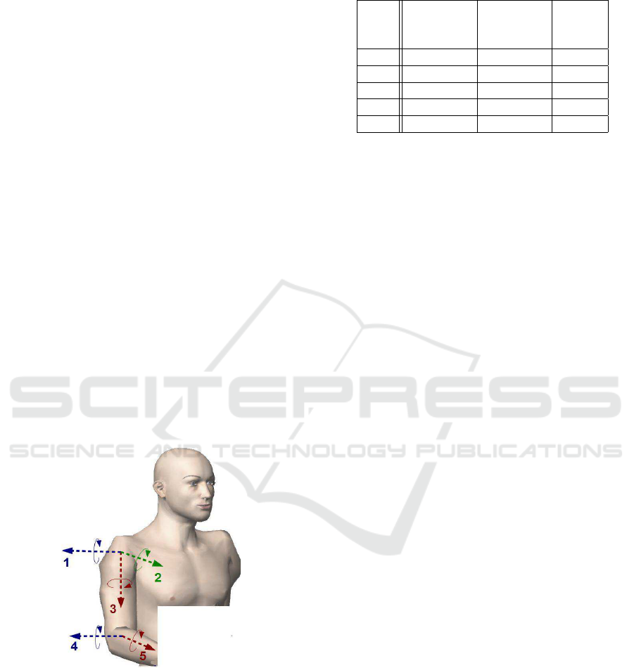
Upper limb rehabilitation devices require movement
of shoulder joint and elbow joint for both limbs. The
movement of the shoulder and elbow are contributed
to the rotation and translation of the wrist. Shoulder is
the most complex joint in the human arm i.e., move-
ment of the shoulder joint can be estimated as rotation
in single ball-and-socket joint with 3 DOFs. Elbow
has a hinge joint which can rotate with 2 DOFs as
shown in Fig. 1. The human arm torque requirements
during daily activities are presented in table 1.
Figure 1: Shoulder and Elbow rotations.
2.2 Hybrid Mechanical Structure
Design
When considering the construction of a robotic de-
vice, there is a choice between serial and parallel
mechanisms (Chen et al., 2014). The key difference
between serial mechanisms and parallel mechanisms
is in their kinematics structures. Parallel mechanisms
Table 1: Torque Requirement for each rotation (Rosen et al.,
2005).
Torque 5 % ADL
joint Human Torque Torque
max [Nm] max [Nm] [Nm]
1 115 5.75 10
2 134 6.5 10
3 60 3 3.1
4 68 3.4 3.8
5 72 3.6 3.8
are composed of, at least, two closed chains that con-
nect a moving platform to a fixed base thus allow-
ing the actuator to be away from the moving plat-
form. For a relatively similar size of the linkages, a
serial mechanism presents a larger workspace volume
than a parallel mechanism. For parallel mechanism,
workspace is compromised by the constraints of all
links that connect the end-effector. For serial mech-
anism, every actuator has to exert enough torque and
power to move all distal links and overhead actuators.
However, the actuators of a parallel mechanism can
be placed on ground to support stronger payload than
a serial mechanism does. It can be made so for se-
rial mechanisms, but at the cost of complex transmis-
sion mechanisms and this is not always possible for
all the links. For parallel mechanism, the geometri-
cal errors are not accumulated, as all the branches are
connected to the end-effector. The dimension accu-
racy of each link must be high so that the position and
orientation of the end effector is more accurate than a
serial mechanism. For serial mechanism, the geomet-
rical errors are accumulated for each link. Therefore,
the end effector will have lower position accuracy.
For serial mechanism (Laycock and Day, 2003), each
chain increases the total inertia while it decreases the
total stiffness. Parallel mechanisms do not exhibit the
above problem and have a much higher stiffness (Bir-
glen et al., 2002). The disadvantage over serial mech-
anisms is that the mechanism’s elements can physi-
cally interfere. The advantages of both mechanisms
are incorporated by combining them in a hybrid con-
figuration (Baser et al., 2006) that includes both par-
allel and serial linkages. By using hybrid configura-
tions, the stiffness remains relatively high and a large
workspace can be achieved.
Our design contains 5 DOF: there is 2 DOF
parallel mechanism which insures the abduc-
tion/adduction, flexion/extension rotations of the
shoulder. This parallel mechanism consists in
two legs (chains), each being regarded as a serial
manipulator. The first chain constitutes a two-axes
serial manipulator and the second chain constitutes
a three-axes serial manipulator. These two chains
Mechatronics Design, Modeling and Preliminary Control of a 5 DOF Upper Limb Active Exoskeleton
399

are coupled through a moving part that supports
a third 3 DOF serial chain. The first DOF of this
chain ensures the lateral rotation/medial rotation of
the shoulder. The fourth and fifth rotations ensure
the flexion/extension and the abduction/adduction
rotations of the elbow. The design of our device
was performed and validated under the SolidWorks
software.
2.3 Actuation, Transmission and
Reduction
The actuation, the reduction and the transmission are
closely coupled and must be designed together. They
are selected according to the requirements specified in
the last subsection. The type of the incorporated actu-
ators affects the overall weight of the device. In most
cases, a good actuator should be compact and light
as well as capable of producing the necessary power
to deliver necessary forces. There are tradeoffs be-
tween power, volume and weight since actuators ca-
pable of producing large forces are generally heavier
and are larger in size than those actuators capable of
smaller forces. The dimensioning procedure of the
actuator was performed under MotionWorks plug-in
of Solidworks, by applying dynamic forces on device
end-effector and then obtaining the required actuator
torques. We select brushed Maxon DC motors with
a low inertia and low friction, which are suitable for
this kind of devices. Maxon RE40 is used for the ab-
duction/adduction, flexion/extension rotations of the
shoulder and RE25 for the flexion/extension and the
abduction/adduction rotations of the elbow and the
lateral rotation/medial rotation of the shoulder.
In order to provide the highest amount of fidelity,
direct drive (absence of transmission of reduction) is
likely to be the best solution. However, this solu-
tion does not provide adequate forces/torques needed
for our application, which we saw earlier is criti-
cal. Among the other transmission and reduction
techniques such as the use of linkages, cables, steel
belts, shafts plus gears, this last one gives the worst
case (Hayward, 1995) since it causes high backlash
and high back-drive friction due to the gear gaps and
gear friction. Back-drive friction and backlash can be
reduced by using cable driven transmission systems.
Therefore, cable driven transmission technique (cap-
stan) was used in our design.
A solution consists of using a combined reduc-
tion (Planetary gear/capstan) in order to amplify the
torques developed by the actuators. We use plane-
tary gears reduction because it has fewer backlashes
and less friction, especially when the reduction ratio is
small (the reduction ratio are 4 for RE40 actuators and
19 for the RE25 actuators in this case). We have de-
signed capstan reduction mechanisms with a ratio of
20 for the abduction/adduction and flexion/extension
rotations of the shoulder and 10 for the lateral ro-
tation/medial rotation of the shoulder and the flex-
ion/extension and the abduction/adduction rotations
of the elbow. The resulting reduction ratios and the
maximal torque that could be generated for each axis
are presented in Table 2. This solution is able to pro-
vide additional torque for gravity and friction com-
pensation.
Table 2: Reduction ratio and maximal torque for each joint.
J Motor Total Resol. Max Torque
Ratio (N.m)
1 RE40 80 0.009
◦
14.5
2 RE40 80 0.009
◦
14.5
3 RE25 190 0.004
◦
5.6
4 RE25 12 0.06
◦
0.83
5 RE25 190 0.004
◦
5.6
As it was presented previousely, the exoskeleton
should include low inertia, no backlash, light weight
and negligible friction (Laycock and Day, 2003).
Therefore, a compromise has to be reached between
the various design goals. Obtaining negligible fric-
tion can be a problem, particularly when high stiffness
is required. High stiffness implies a stiff mechanical
interface which needs to be constructed from metal
which increase the friction and the overall weight of
the device. This provides a conflict between obtaining
high stiffness while keeping low friction (Baser et al.,
2006)(Laycock and Day, 2003). So that, the materials
used to construct such devices need to be considered
with additional costs. In our design:
• Aluminum was used in order to minimize the de-
flection due to the stiffness of the linkages.
• Cable driven transmission technique was used in
order to overcome backlash deflection.
• Stainless steel ball bearings and high precision
manufacturing methods were used in order to
overcome joint deflections.
The Computer Aided Design (CAD) model of the ex-
oskeleton is shown in Figure 2 and table 3.
2.4 Stress and Deflection Analysis
After the completion of the preliminary mechanical
design procedure, links shape and thickness must be
optimized to satisfy the design requirements men-
tioned before, such as the reduction of the inertia of
the device and the maximization of the stiffness. For
this structure, the links stress analysis is carried out
using COSMOSXpress plug-in of Solidworks. Static
ICINCO 2016 - 13th International Conference on Informatics in Control, Automation and Robotics
400
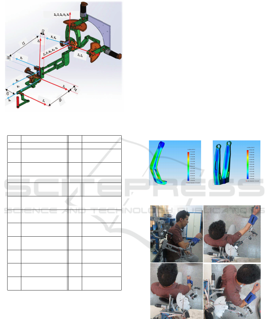
Figure 2: CAD Model of the designed exoskeleton.
Table 3: Parts designation for the CAD model.
N
◦
Designation N
◦
Designation
01 Motor 1 (RE40) 13 Body 2
02 Gear 14 Capstan 4
(GP42) (12:1)
03 Capstan 1 (20:1) 15 Adjustable
(20:1) link
04 Body 1 16 Body 4
05 Motor 3 17 Capstan 3
(RE25) (10:1)
06 Encoder 3 18 Body 3
(HEDS 5540)
07 Encoder 4 19 Capstan 2
(HEDS 5540) (20:1)
08 Motor 4 20 Encoder 2
(RE25) (HEDS 5540)
09 Encoder 5 21 Motor 2
(HEDS 5540) (RE40)
10 Motor 5 22 Gear
(RE25) (GP42)
11 Capstan 5 23 Fixed base
(10:1)
12 End-effector 24 Encoder 1
(HEDS 5540)
analysis of the mechanical design would be sufficient
because the device will be used with low speeds. The
links shape and weights are computed for aluminum
with a Young modulus of 69000 MPa and a mass den-
sity of 2700 kg/m
3
as construction material. This ma-
terial is used because of its high yield strength over
weight ratio. According to the analysis results, the
shape and the thickness of the links should be mod-
ified in iterations. The weight values of the motors,
reductors and links starting from the tool tip and mov-
ing to the base of the robot are used to determine the
static load on the robot links.
In Figure 3, an example of deformation and dis-
tribution of von-Mises stresses are illustrated for two
links of the manipulator. Contour diagram and max-
imum stress points are shown in the figures. Legend
on the right side of the figure shows the distribution of
contour diagram. Legend on the right hand side of the
figure shows the distribution of contour diagram. In
this analysis, deformation in the translational move-
ment direction is studied under static loading of 50 N,
which corresponds to the maximum force that shall be
applied during MIS procedures. Naturally, maximum
deflection occurs at the end of the links. The maxi-
mum and minimum deformation points are shown in
the figure. It has been observed that the link 1 and 3
(parts 06 and 17 in table 3) are the most critical links
since they are exposed to maximum stress in any con-
dition. The shape and thickness of the links are op-
timized according to the maximum deflection values
obtained from the analysis. Figure 4 represents the
manufactured exoskeleton.
Figure 3: Von-Mises Stress analysis of links 1 (left) and 3
(right).
Figure 4: Final prototype of the exoskeleton.
3 EXOSKELETON MODELING
3.1 Kinematic Modeling
Figure 5 shows the position of the frames attach-
Mechatronics Design, Modeling and Preliminary Control of a 5 DOF Upper Limb Active Exoskeleton
401
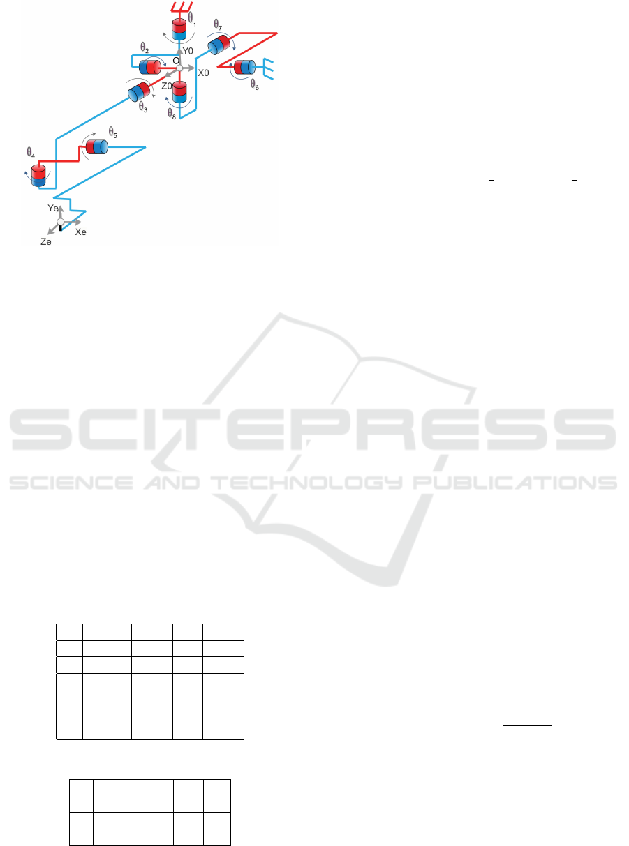
Figure 5: Kinematics of the exoskeleton.
ments. All the frames intersect at one point named ’O’
situated at the center of the moving platform that con-
nects the two parallel chains to each other, thus sim-
plifies the kinematics modeling. For each chain, the
kinematics model is obtained by using the modified
method of Denavit and Hartenberg (Khalil and Dom-
bre, 1999), where
i−1
R
i
represents the rotation ma-
trix from the frame F
i−1
(x
i−1
,y
i−1
,z
i−1
) to the frame
F
i
(x
i
,y
i
,z
i
).
Kinematics parameters are defined in tables 4
and 5, where α
j
represents the joint offsets, r
j
and L
j
the link lengths and θ
j
the joint variables. The mov-
ing platform is a body of both Chain 1 and Chain 2. In
Chain 1, it is referenced by the frame F
2
and in chain 2
by F
6
. So that, the kinematics constraints representing
the closure condition of the parallel structure formed
by Chain 1 and Chain 2 are then:
θ
2
= arctan(tan(θ
6
)/C
1
) (1)
Table 4: DHM kinematics parameters of Chain 1.
j α
j
L
j
θ
j
r
j
1 π/2 0 θ
1
0
2 π/2 0 θ
2
0
3 π/2 0 θ
3
L
0
4 −π/2 −L
1
θ
4
−L
2
5 −π/2 L
3
θ
5
L
4
6 −π/2 0 0 L
5
Table 5: DHM kinematics parameters of Chain 2.
j α
j
d
j
θ
j
r
j
6 −π/2 0 θ
6
0
7 −π/2 0 θ
7
0
8 −π/2 0 θ
8
0
and:
θ
7
= arctan2
(S
1
S
2
),±
q
1 − (S
1
S
2
)
2
θ
6
= arctan2
C
1
S
2
C
7
,
C
2
C
7
θ
8
= arctan2
S
1
C
2
C
7
,
C
1
C
7
(2)
Where Ci and Si stand for cos (θ
i
) and sin (θ
i
), respec-
tively.
The angular positions of the passive joints θ
2
, θ
7
and θ
8
are computed based on the angular positions
of the active joints θ
1
and θ
4
. Expressions (1) and (2)
are not defined for θ
1
= ±
π
2
and θ
2
= ±
π
2
. Fortu-
nately, all these configurations are outside the reach-
able workspace.
The orientation and position of the end-effector is
determined by taking the joint angles of the linkages
and using the forward kinematics calculation as fol-
lows:
0
T
e
=
0
T
1
1
T
2
2
T
3
3
T
4
4
T
5
5
T
e
0
T
e
=
s
x
n
x
a
x
0
p
x
S
y
n
y
a
y
0
p
y
s
z
n
z
a
z
0
p
z
0 0 0 1
Thus, the kinematic model of the exoskeleyon is de-
fined as follows:
0
p
x
= S
1
(−S
2
C
3
(L
2
+ l
5
S
5
) + S
2
S
3
(−L
1
+ L
3
S
4
+L
4
C
4
+ L
5
C
5
) +C
1
((L
5
C
5
S
4
+ L
3
S
4
+L
4
C
4
− L
1
)C
3
+ S
3
(L
5
S
5
+ L
2
))
4
+ l
0
))
−C
2
(L
5
C
5
C
4
+ l
3
C
4
− L
4
S
4
+ L0))
0
p
y
= C
2
(S
3
(L
5
C
5
S
4
+ L
3
S
4
+
L
4
C
4
− L
1
) −C
3
(L
5
S
5
+ L
2
))
+S
2
((L
3
+ L
5
C
5
)C
4
− L
4
S
4
+ L
0
)
0
p
z
= S
1
(S
2
C
3
(L
2
+ L
5
S
5
) − S
2
S
3
(−L
1
+ L
3
S
4
+ L
4
C
4
+ L
5
C
5
)
+S
1
((L
5
C
5
S
4
+ L
3
S
4
+
L
4
C
4
− L
1
)C
3
+C
3
(L
5
S
5
+ L2))
+C
2
(L
5
C
5
C
4
+ L
3
C
4
− L
4
S
4
+ L
0
))
(3)
where
0
p
x
,
0
p
y
,
0
p
z
represents the position of the end-
effector defined in the frame
0
F and (s, n, a) its ori-
entation. We use the Euler angles (α,β ,γ ) in order to
define this orientation as follows:
β = arctan2
−s
z
,
p
s
x
2
+ s
y
2
α = arctan2(s
y
/cos(β),s
x
/cos(β))
γ = arctan2(n
z
/cos(β),n
y
/cos(β))
(4)
where :
• α defines the rotation around the Z
0
axis.
• β defines the rotation around the Y
0
axis.
• γ defines the rotation around the X
0
axis.
ICINCO 2016 - 13th International Conference on Informatics in Control, Automation and Robotics
402

and
s
x
= C
4
(S
1
S
2
S
3
+C
1
C
3
) + S
1
C
2
S
4
s
y
= C
2
S
3
C
4
− S
2
S
4
s
z
= C
4
(C
1
S
2
S
3
− S
1
C
3
) −C
1
C
2
S
4
n
y
= S
4
(C
2
S
3
S
5
+C
4
S
2
) +C
2
C
3
C
5
n
z
= S
5
(S
4
(S
1
C
3
−C
1
S
2
S
3
) + S
1
C
2
C
4
) +C
2
C
3
C
5
(5)
The workspace of the exoskeleton is presented in Ta-
ble 6.
Table 6: Designed exoskeleton vs human arm workspace
comparison.
j Joint Human arm Exoskeleton
Adduction
1 /abduction -45/180
◦
-45/100
◦
(shoulder)
Extension
2 /flexion -50/180
◦
-45/100
◦
(shoulder)
External
3 /internal -80/90
◦
-70/70
◦
rotation
Adduction
4 /abduction 0/200
◦
0/140
◦
(Elbow)
Extension
5 /flexion 0/145
◦
0/140
◦
(Elbow)
3.2 Jaccobian Matrix
The Jacobian matrix J is one of the most important
quantities in the analysis and control of robot motion.
It arises in virtually every aspect of robotic manipu-
lation: in the planning and execution of smooth tra-
jectories, the execution of coordinated anthropomor-
phic motion, in the derivation of the dynamic equa-
tions of motion, and in the transformation of forces
and torques from the end-effector to the manipulator
joints and in the determination of singular configura-
tions.
The resulting Jaccobian matrix of the exoskeleton
is defined as follows:
J =
J
11
J
12
J
13
J
14
0
J
21
J
22
J
23
−L
4
S
5
−L
5
J
31
J
32
J
33
−C
5
L
4
0
J
41
−C
4
C
3
−S
4
0 1
J
51
J
52
S
5
C
4
C
5
0
J
61
J
62
C
4
C
5
−S
5
0
(6)
where,
J
11
= C
1
(C
3
(−(C
5
L
6
+ L
4
)S
4
− L
5
C
4
+ L
2
)
−S
3
(S
5
L
6
+ L
3
)) − S
1
(S
2
(−S
3
(−S
3
(−(C
5
L
6
+ L
4
)S
4
− L
5
C
4
+ L
2
)
−C
3
(S
5
L
6
+ L
3
))
+C
2
(C
4
(C
5
L
6
+ L
4
) − S
4
L
5
+ L
1
))
J
12
= (−S
5
S
4
C
3
+C
5
S
3
)L
5
−C
3
L
2
S
4
+S
3
(C
4
L
0
− L
1
S
4
+ L
3
)
J
13
= S
5
C
4
L
5
+C
4
L
2
J
14
= C
5
L
5
+ L
3
J
21
= ((L
3
S
3
C
2
− L
4
S
2
)C
4
+(−L
4
S
3
C
2
− S
2
L
3
)S
4
+L
1
S
2
+ S
3
C
2
L
0
)C
5
+ (−C
2
(−L
2
S
3
+ L
1
C
3
)C
4
+ (−C
3
C
2
L
0
− L
2
S
2
)
S
4
+ L
4
C
3
C
2
)S
5
+ L
5
(C
4
S
3
C
2
− S
2
S
4
)
J
22
= ((L
2
C
3
+ L
1
S
3
)C
4
+ S
3
L
0
S
4
−L
4
S
3
)S
5
+ L
5
C
4
C
3
+(L
3
C
3
C
4
− L
4
C
3
S
4
+C
3
L
0
)C
5
J
23
= (L
4
C
4
+ L
3
S
4
− L
1
)C
5
+L
2
S
4
S
5
+ L
5
S
4
J
31
= ((L
4
S
2
− L
3
S
3
C
2
)C
4
+ (L
4
S
3
C
2
+ S
2
L
3
)S
4
−S
3
C
2
L
0
− L
1
S
2
)S
5
−C
5
(C
2
(−L
2
S
3
+ L
1
C
3
)C
4
+ (L
2
S
2
+C
3
C
2
L
0
)S
4
− L
4
C
3
C
2
)
J
32
= (−(L
2
C
3
+ L
1
S
3
)
C
4
− S
3
L
0
S
4
+ L
4
S
3
)
−C
5
(−L
3
C
3
C
4
+ L
4
C
3
S
4
−C
3
L
0
)S
5
J
33
= (−L
4
C
4
− L
3
S
4
+ L
1
)S
5
+C
5
L
2
S
4
J
41
= S
2
S
4
−C
4
S
3
C
2
J
51
= (−S
4
S
3
C
2
−C
4
S
2
)S
5
−C
5
C
3
C
2
J
52
= −S
5
S
4
C
3
+C
5
S
3
J
61
= (−S
4
S
3
C
2
−C
4
S
2
)C
5
+ S
5
C
3
C
2
J
62
= −S
4
C
3
C
5
− S
5
S
3
(7)
4 ELECTRONICS INTERFACE
AND PRELIMINARY CONTROL
LOOP DESIGN
4.1 Position and Current Sensing
The angular positions of the five active joints are mea-
sured thanks to five incremental encoders type HEDS
5540 from Maxon. These encoders are placed in the
rear of the motors and provide 500 pulsations per rev-
olution of the motor axis. Thus, the position measure-
ment resolution is computed by taking into account,
the reduction ratio ((360/500)/N, while N is the re-
duction ratio). Table 2 presents the angular position
resolution of each joint. Current sensors type LTS 15-
NP are also integrated in order to measure the actua-
tor’s current. The measured current is used in order to
estimate the actuator’s torque.
Mechatronics Design, Modeling and Preliminary Control of a 5 DOF Upper Limb Active Exoskeleton
403
4.2 Electronics Interface
The control setup consists in a dSPACE DS1103 Con-
trol Board which is a versatile and powerful real-time
measurement and control board. The power stage is
designed based on two OPA541 and three OPA548
operational power amplifiers from Burr-Brown which
are able to provide a current about 10 for RE40 mo-
tors and 3A for RE25 motors respectively (Fig. 6).
Linear Power
Amplifier (01)
OPA541
DC Motor (02)
Maxon RE40
DC Motor (04)
Maxon RE25
Incremental Encoder
(01) HEDS 5540
Linear Power
Amplifier (03)
OPA548
Linear Power
Amplifier (04)
OPA548
Linear Power
Amplifier (05)
OPA548
DC Motor (03)
Maxon RE25
DC Motor (05)
Maxon RE25
DAC02
DAC03
DAC04
DAC05
Incremental Encoder
(02) HEDS 5540
Incremental Encoder
(03) HEDS 5540
Incremental Encoder
(04) HEDS 5540
ENC01
ENC02
ENC03
ENC04
ADC01
Current sensor (01)
Current sensor (02)
Current sensor (03)
ADC02
ADC03
ADC04
Dspase DS1103
Board
Current sensor (04)
Current sensor (05)
Incremental Encoder
(05) HEDS 5540
ENC05
ADC05
Linear Power
Amplifier (02)
OPA541
DC Motor (01)
Maxon RE40
DAC01
Figure 6: Overview of the electronics interface.
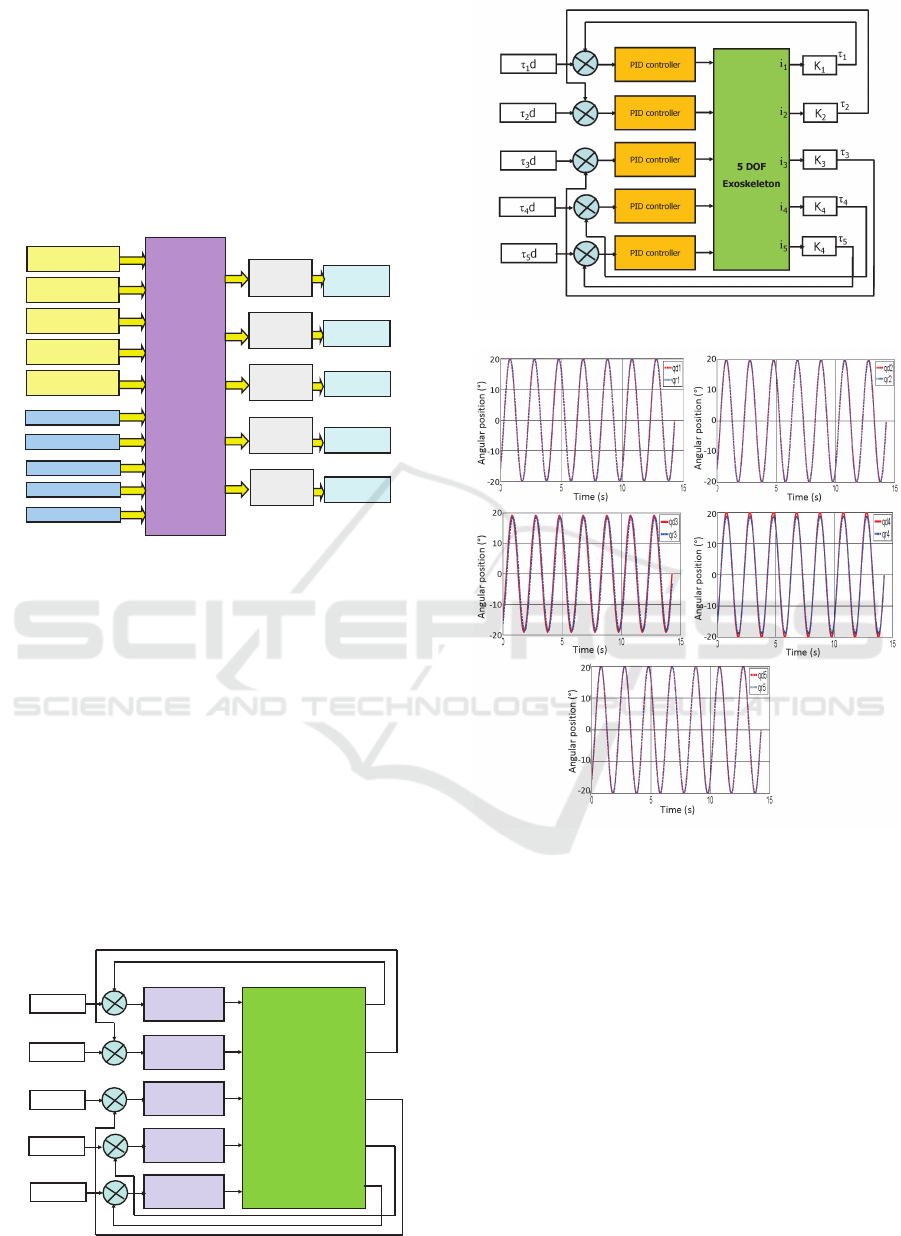
4.3 Preliminary Control Loop Design
In order to assess the model and to evaluate the per-
formances of the assembled exoskeleton, basic posi-
tion and torque control loops are implemented. We
used proportional-derivative (PD) and proportional-
derivative-intergral (PID) controllers respectively for
each joint of the exoskeleton (see Fig.7 for position
control and Fig.8 for torque control). In Fig.8, con-
stants K
i
(i = 1,...5) represent the torque constants of
the actuators.
These preliminary controllers have been imple-
mented successfully. Figure 9 presents an example
of the obtained results for sinusoidal position track-
ing while Fig. 10 presents an example of the obtained
PD controller
LJ
1
d
LJ
2
d
5 DOF
Exoskeleton
LJ
1
LJ
2
LJ
5
LJ
3
d
LJ
4
d
LJ
5
d
LJ
3
LJ
4
PD controller
PD controller
PD controller
PD controller
Figure 7: Preliminary position control scheme.
Figure 8: Preliminary torque control scheme.
Figure 9: Articular position control example.
results for square torque tracking. These results show
that the PD controller allows improving the time re-
sponse of the system and eliminating the static error
in the position control loop in a stable way. Simi-
lar remarks are recorded for the torque controller. So
that, and since the first instant, the resulting trajec-
tory converges faster to the desired one. These results
show the good tracking capability of the developped
exoskeleton.
5 CONCLUSION
A new exoskeleton has been designed and realized for
the upper limb rehabilitation objective. This new de-
vice takes benefits from both the advantages of serial
ICINCO 2016 - 13th International Conference on Informatics in Control, Automation and Robotics
404
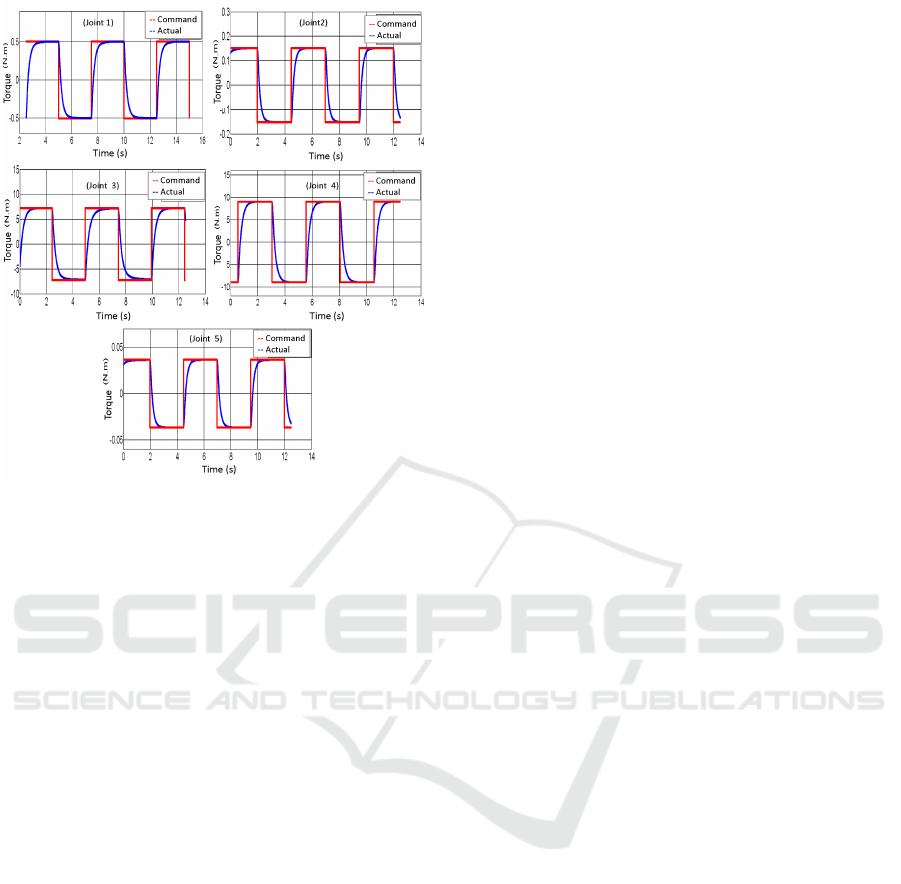
Figure 10: Articular torque control example.
mechanisms and parallel mechanisms. It allows mov-
ing the shoulder joint around three axes and the elbow
around two axes. Kinematics of the exoskeleton has
been computed, and its capabilities have been deter-
mined and compared to the requirements. Preliminary
position and torque control loops have been imple-
mented in order to evaluate the basic performance of
the device in term of position and torque tracking. Fu-
ture works will concern a bandwidth analysis, model
based control, admittance control, and clinical evalu-
ation of the exoskeleton.
REFERENCES
Baser, O., Konukseven, E. I., and Koku, B. (2006). 7 dof
haptic device design. In EuroHaptics 2006, pages
507–512.
Birglen, L., Gosselin, C., and Pouliot, N. (2002). Shade,
a new 3-dof haptic device. IEEE Transactions on
Robotics and Automation, 18(2):166–175.
Chay, K.-H., Lee, J.-V., Chuah, Y.-D., and Chong, Y.-Z.
(2014). Upper extremity robotics exoskeleton: Appli-
cation, structure and actuation. International journal
of Biomedical Engineering and Science, 1(1):35–45.
Chen, Y., Li, G., Zhu, Y., Zhao, J., and Cai, H. (2014).
Design of a 6-dof upper limb rehabilitation exoskele-
ton with parallel actuated joints. Biomed Mater Eng.,
24(6):2527–2535.
Gopura, R. C., Kiguchi, K., and Bandara, S. V. (2011). A
brief review on upper extremity robotic exoskeleton
systems. In 6th IEEE International Conference on In-
dustrial and Information Systems, pages 346–351.
Hayward, V. (1995). Toward a seven axis haptic device.
In International Conference on Intelligent Robots and
Systems, pages 31–33, Washington, DC, USA. IEEE
Computer Society.
Jarrassee, N., Proietti, T., Crocher, V., Robertson, J., Sah-
bani, A., Morel, G., and Roby-Brami, A. (2014).
Robotic exoskeletons: A perspective for the rehabili-
tation of arm coordination in stroke patients. Frontiers
in Human Neuroscience, 8(947).
Khalil, W. and Dombre, E. (1999). Mod
´
elisation, identifi-
cation et commande des robots. Collection robotique.
Laycock, S. D. and Day, A. M. (2003). Recent develop-
ments and applications of haptic devices. Computer
Graphics, Blackwell Publishing Ltd, 22(2):117–132.
Maciejasz, P., Eschweiler, J., Gerlach-Hahn, K., Jansen-
Troy, A., and Leonhardt, S. (2014). A survey on
robotic devices for upper limb rehabilitation. Journal
of NeuroEngineering and Rehabilitation, 11(3):1–29.
Rosen, J., Perry, J. C., Manning, N., Burns, S., and
Hannaford, B. (2005). The human arm kinemat-
ics and dynamics during daily activities-toward a 7
dof upper limb powered exoskeleton. In Advanced
Robotics, 2005. ICAR’05. Proceedings., 12th Interna-
tional Conference on, pages 532–539. IEEE.
Mechatronics Design, Modeling and Preliminary Control of a 5 DOF Upper Limb Active Exoskeleton
405
