
Autonomous Surface Vessel based on a Low Cost Catamaran Design
Santiago Puente, Francisco Candelas, Fernando Torres and Dzmitry Basalai
Physics, Systems Engineering and Signal Theory Department, University of Alicante,
Carretera De San Vicente s/n, 03690,San Vicente del Raspeig, Alicante, Spain
Keywords:
Marine Robotics, Autonomous Surface Vessel, ASV.
Abstract:
Nowadays, Robotics is increasing its importance for the marine environment in our society. It allows to
perform surveillance and data sampling tasks reducing the current cost of these tasks. This paper presents the
design of a prototype of an Autonomous Surface Vessel (ASV) based on catamaran shape. It uses the screw
theory for the propulsion system, which provides high manoeuvrability to the vessel. Furthermore, the parts
of the ASV are designed to be printed by a RepRap 3D printer. This gives flexibility to check the performance
of the vessel. Also the software control scheme of the vessel is presented.
1 INTRODUCTION
Among the last years, a research focus in Au-
tonomous Underwater Vehicles (AUV) has emerged
(Russell B. Wynna, 2014) (Salimzhan A. Gafurov,
2015), and the marine environment is becoming in a
good field for research in autonomous robots. Not
lot of research have been performed in Autonomous
surface vessel (ASV), but this research area is becom-
ing more popular because the necessity to understand
marine environment, not only underwater environ-
ment, although surface one (Ferri et al., 2015). Nowa-
days, the coordination of both approaches, underwa-
ter and surface one, allows to improve the global
understanding of the marine environments (Roberts,
2008). There are a lot of research groups that are de-
veloping their own ASV to be used for testing sce-
narios and algorithms (Pascoal et al., 2000). The ma-
jority of that type of vessels are mainly designed for
observation and sampling different parameters of the
environment (Manley, 1997) (Caccia et al., 2007).
There are a large number of new ASVs that are
single hull or catamaran shaped, that provide good hy-
drodynamic characteristics. Some of them provide a
different shape, which allows a better maneouverity
(ula Nad et al., 2015). In this paper, a mix among dif-
ferent shapes and control systems is provided in order
to design and build a new prototype of ASV. This pa-
per presents a catamaran shape vessel with an screw
propulsion which allows it to have a great maneuver-
ity in any direction. Furthermore, another character-
istic of the ASV designed is that the hull and others
parts of the vessel are built using a 3D printer, what
reduces considerable the cost against other manufac-
turing techniques, and allows fast check of the vessel
parts.
Next, in Section 2, the design of the ASV proto-
type is described. In Section 3 the software architec-
ture of the ASV is presented. The construction results
of the ASV are shown in Section 4. Finally, in Section
5, the conclusions are shown.
2 DESIGN OF THE
AUTONOMOUS SURFACE
VESSEL
The prototype proposed is a vessel based on a catama-
ran design. It uses two screw traction system (Hunt,
2003) for its propulsion. Another advantage of the
presented design is that it is able to move on differ-
ent types of fluids, due to it’s propulsion system. That
point provide more flexibility to operate in areas with
low level of water, or when a operation starting from
shore is necessary. Furthermore, it allows the ves-
sel to stabilise in any position and provides great ma-
neouverity. Other important aspect of the vessel de-
sign and implementation that has been considered is
the low cost of the vessel and the refurbishment of its
parts. In order to accomplish that objective, first the
hull and components of the vessel havebeen modelled
using FreeCad (Falck and Collette, 2012), which al-
low to design all the parts in a fast way. Moreover,
this design enables us to print the model in a RepRap
printer (Jones et al., 2011) nearly directly. The model
452
Puente, S., Candelas, F., Torres, F. and Basalai, D.
Autonomous Surface Vessel based on a Low Cost Catamaran Design.
DOI: 10.5220/0005987404520457
In Proceedings of the 13th Inter national Conference on Informatics in Control, Automation and Robotics (ICINCO 2016) - Volume 2, pages 452-457
ISBN: 978-989-758-198-4
Copyright
c
2016 by SCITEPRESS – Science and Technology Publications, Lda. All rights reserved
has been divided in small sections in order to enable
the printing by using a popular standard 3D printer
with a small working area.
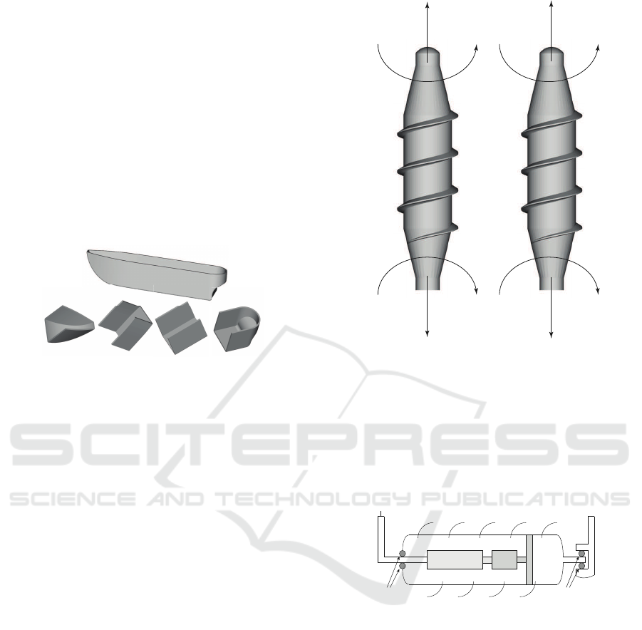
The obtained prototype has a 600mm of length,
450mm of beam and 400mm of heigh. The catama-
ran is supported on two hulls of 600mm of length.
These hulls compose the main part of the ASV. They
are used like the basement of ASV and for storage
the power supply and required sensors for the possible
missions. Figure 1 represents the 3D model of the hull
with the division required to print it by the 3D printer.
The same happens to the parts of the ASV that are
greater than 200mm, which is the biggest print size
that allow the printer used.
Figure 1: Hull and parts for 3D printer.
Other part of the vessel is the propulsion system
which is based on the screw theory. The ASV pro-
posed has two propellers in screw shape which allows
to control the movement of the vessel in any direc-
tion according the rotation direction and speed of each
motor (Figure 2). The movement of the vessel is gen-
erated when port motor and starboard motor gener-
ate a forward direction thrust. Each motor generates
a rotation r
1
and r
2
with provide the forces F
1
and
F
2
respectively, which moves forward the vessel. If
both, port motor and starboard motor, rotates in back-
ward direction, generate a rotation r
3
and r
4
which
provide the forces F
3
and F
4
respectively, moving the
vessel backward. It is possible generate a yaw rota-
tion movement with stable holding position by using
a combination of different speeds for port and star-
board motor.
The port and starboard motors are design to be
fit inside a case, with a gearbox, bearings, and the
necessary seals for avoiding water to fill in the motor
space (Figure 3). When the motor rotate, it gener-
ates a movement in the gearbox which increase the
torque to move the case. This case acts as a propeller
thanks to it has a screw shape in its outside face. The
two sets of motors and gear-boxes have been obtained
from cheap battery screwdrivers. Furthermore, in the
front part of the case, a tube has been used to hold
the case to the hull of the vessel, and wires to the mo-
tor are contained in this tube. This tube has a bearing
around it to allow the case to rotate with the motor
axis and leaving the motor static. Thanks to this de-
r
1
r
2
F
3
F
4
r
3
r
4
F
1
F
2
Starboard
motor
Port
motor
Figure 2: Propulsion vectors system for vessel movement.
sign, it is not necessary to drive any mechanical trans-
mission of movement from the vessel to the propeller.
Besides, only two wires to give the power to the mo-
tor are necessary from the vessel to the propeller. This
simplifies largely the mechanical design. The case
and the connectors are designed to be printed using
the 3D printer.
Motor Gearbox
Bearing and sealing Bearing and sealing
Wires
Tube
Figure 3: Port and Starboard motor design.
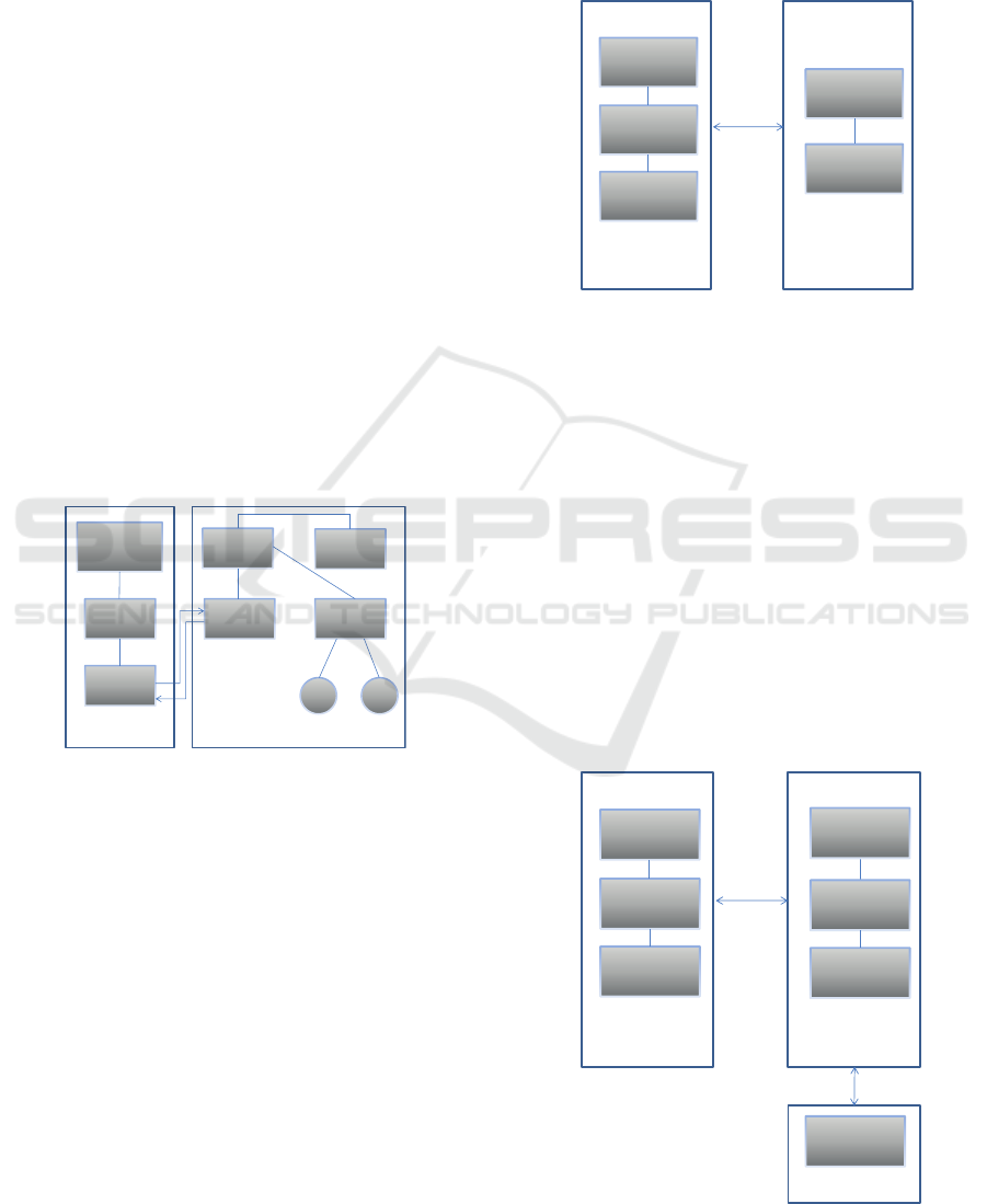
After the design of the ASV was performed, the
control and software architecture of the system were
detailed. The designed vessel uses the control scheme
architecture shown in Figure 4. The architecture is di-
vided in two main parts: base control station and on-
board control system. The base control station uses
a Laptop as main control core. it is used for high
level veseel control and general acquisition. It com-
municates with a Arduino board through a serial-USB
port which provides the communication thought Xbee
module with the onboard control system. The main
core of the onboard control system is a phone. A
Android based mobile phone, which, which is used
to provide GPS coordinates to obtain the location of
the vessel in any moment. Furthermore, it provides
the intelligence embedded in the ASV. The use of a
Autonomous Surface Vessel based on a Low Cost Catamaran Design
453
mobile phone provides low cost sensors, communi-
cation system and computation power. Furthermore,
the phone is used to calculate current destination az-
imuths and distances between two locations points.
To communicate with the base control station, a XBee
module is used, which is connected to an Arduino
ADK. The Arduino ADK receives data from phone
and transmits it through Xbee module to base con-
trol station. This communication is in both senses. A
XBee module based on technologies such as Zigbee
or 802.15.4 provides a line-of-sight range larger that
other radio options like WiFi (Lee and Lin, 2016).
Furthermore, XBee communication solves the prob-
lem. This solves the problem of using GSM commu-
nication has with places with low or null coverage. In
addition, the Arduino ADK provides communication
with motor driver board to control motor operation
according to required trajectory. A high efficiency
VNH5019 motor driver based on MOSFET from ST
Microelectroncis has been used, which allows to con-
trol the current and speed of the two motors, port and
starboard ones, by means of PWM signals. The con-
trol signal is generated using a PWM signal as ref-
erence. The motor driver allows the control of both
motors, the port and starboard ones.
LapTop
Arduino
Mega
Xbee
module
XBee
module
Arduino
ADK
Phone
Motor
driver
Port
motor
Base control
sta!on
Onboard control system
Starboard
motor
Figure 4: Architecture control scheme of ASV.
3 SOFTWARE SYSTEM
The software system has two main modules, one in
the base control station and the other in the onboard
control system. The base control system has to per-
form the following main task, as shown in Figure 5:
• Receive current location information (longitude,
latitude, speed, accuracy, bearing, altitude) from
onboard control system.
• Sending target trajectory information to the on-
board control system.
• Show vessel information in the user interface.
• Interact with the user to process his commands.
The information from the vessel is received by the
XBee module and passed to the Arduino, whose only
task is to validate and retransmit the information to
the laptop, which is the responsible of processing it
and showing in the user interface.
Arduino ADK
& XBee
Show ship
informa!on
Receive current
loca!on
Send target
parameters
Interact with
user
Calculate
trajectory
User interface
Figure 5: Software base control station scheme.
Onboard control system has to perform the next
tasks that are represented in Figure 6:
• Establish connection between onboard control
system and base control .
• Obtaining current location information (GPS co-
ordinates).
• Computing current navigation parameters: longi-
tude, latitude, speed, accuracy, bearing, altitude.
• Receiving trajectory information from base con-
trol system.
• Calculate orientation and thrust to the target.
• Send onboard information to base control system.
• Control the motors to perform achieve the target.
Arduino ADK
& XBee
Phone
Obtain GPS
coordinates
Receive target
parameters
Send onboard
informa!on
Compute current
loca!on
Calculate thrust
& orienta!on
Generate motor
reference
Motor Driver
Port & starboard
motor control
Figure 6: Software onboard control system scheme.
ICINCO 2016 - 13th International Conference on Informatics in Control, Automation and Robotics
454

These tasks are performed by the phone and by
the Arduino ADK. The current location information
and the required orientation and thrust of the vessel to
achieve the target location is computed by the phone.
It uses information from the base control station and
from its own sensors. The information obtained is
transmitted to the Arduino ADK, which has to send
the onboard information to the base control system
and has to generate the control signals for the motor
driver.
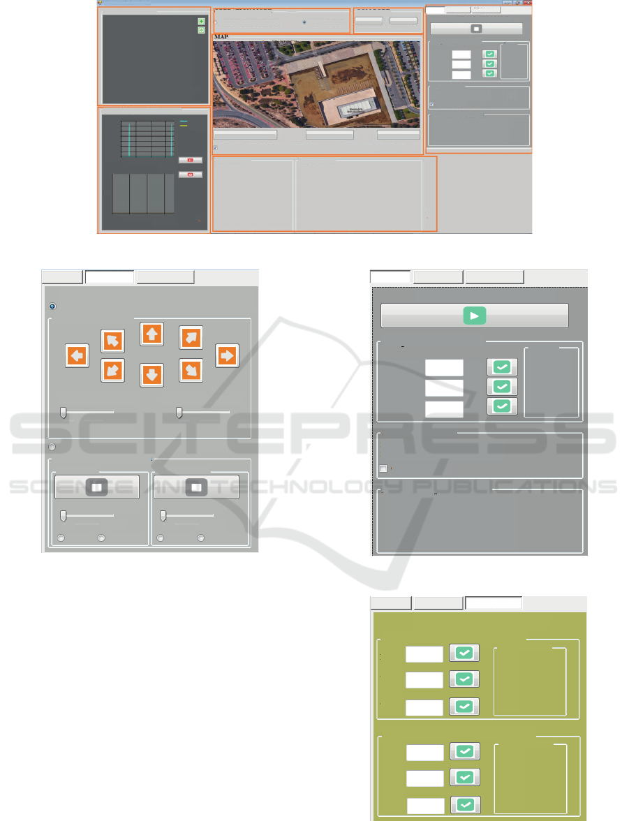
3.1 User Interface
The user interface has been programed by using Mi-
crosoft Visual Studio, providing a Windows applica-
tion to control the ASV. It is located in the base con-
trol station. The application allows the control of the
ASV in two modes: manual and automatic. In man-
ual mode, the operator controls each motor directly.
While the application is in automatic mode, the oper-
ator sends geographical references through a map and
the onboard control system perform the control of the
ASV to reach the target reference.
The user Interface for the ASV is shown in Figure
7. The parts of the interface are:
1. Received data: Field for received data from on-
board control system (longitude, latitude, speed,
altitude, accuracy, angle, etc) .
2. Operation mode: It allows user to choose type of
operation of ASV(automatic or manual).
3. COM Port: Field for selecting the serial port in
which is connected the Arduino Mega. It allows
user to stablish or not communication between
user interface and Arduino.
4. Map: Field to display the current position in a
map. The map is obtained from Google Maps us-
ing the location of the vessel.
5. Field of operation in different modes (Auto
Mode/Manual mode) and adjust the PID parame-
ters. It allows to send information to onboard con-
trol system through Arduino ADK (latitude and
longitude of desired point) based on the opera-
tion parameters like: PID adjustments, control-
ling commands of ASV in manual mode. Further-
more, it allows to receive information from on-
board control system (azimuth, distance)
6. Speed motor manual monde: Field to display
graphs of location in manual and automatic mode
(speed and azimuth).
7. Debug information: Field for debugging and fu-
ture instalation of a webcam in the ASV.
3.1.1 Manual Mode
The manual mode is one of the working modes of the
ASV. In this mode the user can control the vessel with
the control shown in Figure 8. This mode have two
working ways. Fisrt, the ASV control of the trajec-
tory, where the user can control the direction of the
movements of the vessel. Second, the direct motor
control, where the user can control the speed of each
motor of the vessel. Furthermore, in the second mode
the user can connect or disconnect each motor inde-
pendently.
3.1.2 Automatic Mode
The automatic mode. Figure 9 shows the layout of
the interface that allows user to input commands for
the automatic mode. In this mode the target point and
the speed required have to be indicated by the opera-
tor. These information can be introduced directly or
by clicking in the map. The automatic mode a frame
shows the azimuth required to achieve the target loca-
tion and whole distance to it.
3.1.3 PID Adjustment
The vessel on-board system has one PID controller to
control motor speed based on information provided
by the based control system. The vessel has other in-
dependent PID controller to generate trajectory refer-
ences and transform them to thrust and azimuth re-
quired by on-board control system. Figure 10 shows
a interface form that allows user to specify the param-
eters K
p
, T
i
and T
d
of each PID controller.
4 CURRENT RESULTS AND
FUTURE WORK
The result of the work presented in this paper is an
ASV (Figure 11) which a great manoeuvrability and
an interface which provide the operator a good control
of the system.
The ASV has been tested in laboratory environ-
ment to check that all part of the ASV responds prop-
erly. All the parts of the vessel have been printed
and assembled, adding the electronics components
and motors to the system. The communication sys-
tem has been tested with good results and the motors
responds properly to user commands. Furthermore,
the waterproof and buoyancy of the ASV has been
checked with positive results. The next phase will be
to check the vessel on water environment, lake or sea
to perform a real task.
Autonomous Surface Vessel based on a Low Cost Catamaran Design
455
4
RECEIVED DATA
REQUIRED VALUES
Add Markers On Map Add Route Del Markers
Set Destination Coordinates From Map by Click Lat = 38,3594ºN Long = 0,4755ºW
SPEED MOTOR MAN MODE
Autonomous Surface Vessel (ASV)
Auto Mode
Manual Mode
PID Adjustment
AUTOMATIC MODE
Lat =
Long =
Speed =
º
º
[m/s]
38.3594º
-0.4755º
0.0 [m/s]
Values
Current
START POINT
AZIMUTH DISTANCE
Start point Lat = 0 º
Start point Long = 0 º
GPS Start Point
Current azimuth = 359,32 º
Target azimuth = 360 º
Whole distance = 0 [km] 0[m]
Passed distance = 4266 [km] 842,6 [m]
PHONE CONNECTION Connected
GPS ENABLE = TRUE
GPS Status = OUT OF SERVICE
Current Lattitude = 38.3592 º
Current Longitude = -0.4906 º
Current speed = 0 [m/s]
GPS Time = 26.07.2015 21:59:57
Altitude = 138 [m]
Accuracy = 32 [m]
Angle = 0 º
0:0:50 0:1:40 0:2:30
t[h:m:s]
Cur
Target
3.5
3
2.5
2
1.5
1
0.5
0
Speed [m/s]
0:0:50 0:1:40 0:2:30
t[h:m:s]
%
DEBUG INFO
VIDEO CAM
OPERATION MODE
AUTOMATIC MODE
MANUAL MODE
COM PORT
DisconnectCOM35
3
2
1
6
7
5
4
Figure 7: User interface.
CONTROL OF INDIVIDUAL MOTOR
Auto Mode
Manual Mode PID Adjustment
MANUAL MODE
TRAJECTORY CONTROL
USV Trajectory control
Loading Dependency Speed
[%] [%]0 0
Separate motors operation
Port motor
Starboard motor
Speed
Speed
[%]0
[%]0
Direct DirectReverse Reverse
Figure 8: User interface: Manual mode.
5 CONCLUSIONS
The designed ASV prototype provides a different ap-
proach from the existent vessels. It is focused in pro-
viding great manoeuvrability and reducing the costs
of building the parts of the vessel by using a low-cost
3D printer. Also, components including motors and
electronics are cheap and easy to find. Another ad-
vantage of the presented design, as was mentioned be-
fore, is that it can move in different types of surfaces.
This advantage allows the vessel to start a operation
mission from the shore.
One of the main problems of this prototype was
the necessity of dividing the model of the vessel in
several parts to allow us to print it. This could be im-
prove using a bigger 3D-printer that allows us to print
more than 1000mm length prototypes to be printed.
REQUIRED VALUES
Auto Mode Manual Mode PID Adjustment
AUTOMATIC MODE
Lat =
Long =
Speed =
º
º
[m/s]
38.49999º
-45.98789º
7.6 [m/s]
Values
Current
START POINT
AZIMUTH DISTANCE
Start point Lat = start_lat º
Start point Long = start_long º
GPS Start Point
Current azimuth = cur_az º
Target azimuth = target_az º
Whole distance = whole_dist
Passed distance = passed_dist
Figure 9: User interface: Automatic mode.
THRUST: PID ADJUSTMENTS
Auto Mode Manual Mode
PID Adjustment
SETTINGS CONTROL
K
p
=
T
i
=
Current Values
T
d
=
0
0
0
AZIMUTH: PID ADJUSTMENTS
K
p
=
T
i
=
Current Values
T
d
=
0
0
0
Figure 10: User interface: PID adjustment.
ICINCO 2016 - 13th International Conference on Informatics in Control, Automation and Robotics
456
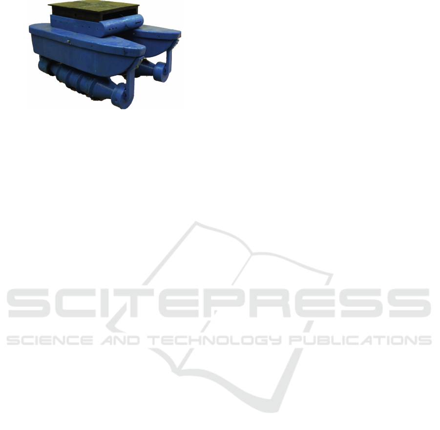
Figure 11: Final prototype of the ASV.
The long distance radio systems allows an auto-
matic or manual operation of the vessel. Furthermore,
in the automatic mode the vessel has autonomy to ar-
rive the target point. Another important aspect of ves-
sel is the motor design. It presents a simple and robust
mechanical structure.
The ASV presented here is a fully equipped plat-
form suitable for many marine research tasks. For de-
veloping specific research the required sensors can be
added. Moreover, to perform more complex task, a
high level control system is required. It will allow the
operator to indicate the desired task. We are working
to improve this point now.
ACKNOWLEDGEMENTS
The research leading to these result has receivedfund-
ing from the Spanish Government (DPI2015-68087-
R) and Valencia Regional Government (PROME-
TEO/2013/085).
REFERENCES
Caccia, M., Bibuli, M., Bono, R., Bruzzone, G., Bruzzone,
G., and Spirandelli, E. (2007). Unmanned surface ve-
hicle for coastal and protected waters applications: the
charlie project. Marine Technology Society Journal,
41(2):62–71.
Falck, D. and Collette, B. (2012). FreeCAD [How-to].
Packt Publishing.
Ferri, G., Manzi, A., Fornai, F., Ciuchi, F., and Laschi, C.
(2015). The hydronet asv, a small-sized autonomous
catamaran for real-time monitoring of water quality:
From design to missions at sea. Oceanic Engineering,
IEEE Journal of, 40(3):710–726.
Hunt, K. H. (2003). Review: Don’t cross-thread the
screw!*. Journal of Robotic Systems, 20(7):317–339.
Jones, R., Haufe, P., Sells, E., Iravani, P., Olliver, V., Palmer,
C., and Bowyer, A. (2011). Reprap the replicating
rapid prototyper. Robotica, 29:177–191.
Lee, H. C. and Lin, H. H. (2016). Design and evaluation
of an open-source wireless mesh networking module
for environmental monitoring. IEEE Sensors Journal,
16(7):2162–2171.
Manley, J. E. (1997). Development of the autonomous
surface craft ldquo;aces rdquo;. In OCEANS ’97.
MTS/IEEE Conference Proceedings, volume 2, pages
827–832 vol.2.
Pascoal, A., Oliveira, P., Silvestre, C., et al.. (2000).
Robotic ocean vehicles for marine science applica-
tions: the european asimov project. In OCEANS 2000
MTS/IEEE Conference and Exhibition, volume 1,
pages 409–415 vol.1.
Roberts, G. (2008). Trends in marine control systems. An-
nual reviews in control, 32(2):263269.
Russell B. Wynna, Veerle A.I. Huvennea, et al. (2014).
Autonomous underwater vehicles (auvs): Their past,
present and future contributions to the advancement of
marine geoscience. Marine Geology, 352:451–468.
Salimzhan A. Gafurov, E. V. K. (2015). Autonomous un-
manned underwater vehicles development tendencies.
Procedia Engineering, 106:141–148.
ula Nad, Mikovic, N., and Mandic, F. (2015). Navigation,
guidance and control of an overactuated marine sur-
face vehicle. Annual Reviews in Control, 40:172 –
181.
Autonomous Surface Vessel based on a Low Cost Catamaran Design
457
