
Towards Multi-Level-Simulation using Dynamic
Cloud Environments
Stefan H. A. Wittek
1
, Michael Göttsche
2
, Andreas Rausch
1
and Jens Grabowski
2
1
Department of Informatics, Clausthal University of Technology, Clausthal-Zellerfeld, Germany
2
Institute of Computer Science, Georg-August-University Göttingen, Göttingen, Germany
Keywords: Co-simulation, Cloud Deployment, Multi-Level-Simulation.
Abstract: The engineering of cyber physical systems requires holistic simulation perspectives. To cope with the
complexity of these systems, we aim to provide a simulation methodology that is efficient regarding model
complexity. The required holistic perspective is reached on a coarse level, which is co-simulated with multiple
detailed models of some areas of the system that are of particular interest to the investigated phenomena.
Which areas are thus “zoomed in” is dynamic during a simulation run. To reflect this, the resulting Multi-
Level-Simulation is deployed in a dynamic cloud environment, using the provided hardware resources in a
cost-efficient manner.
1 MOTIVATION
Cyber physical systems (CPS) consist of numerous
physical and software components. Autonomous cars
and automated production facilities are examples of
such systems. The engineering of CPS is a difficult
task due to the complexity of these systems.
In engineering, simulation has become a core
method. The complexity of a system is abstracted into
an executable model that allows us to evaluate
designs without the need of building physical
prototypes. This reduces the costs and effort involved
in this task.
Applying simulation to CPS provides numerous
chances. Aside from the possible reduction of
prototyping effort, the product can be improved and
its costs can be lowered. Real-time simulations can be
employed at runtime to infer from a few measurement
points to numerous virtual sensors located in between
these physical sensors. This allows to reduce the
amount and quality of sensory used, which in turn
leads to efficient designs. The cost of the system can
also be lowered by allowing deviation in the physical
part of the CPS. If these deviations (i.e. the bending
of a robot arm due to the mass it is lifting) is well
known through simulation, it can be compensated
using the software part of the system. This
compensation in turn can be evaluated in simulation.
Nowadays the simulation of complex systems is
done according to specific simulation questions.
Scenes are modelled in a particular domain
containing only one area of the system using a
specific modelling technique. An example of this is
the thermal behaviour of the cable in the shaft of a lift
using the finite element method, to answer the
question if the lengthening of the cable is beyond a
certain threshold. By doing this, the interdependency
between these scenes is lost.
To acquire a more holistic view, these scenes are
connected directly using a methodology or by
building interfaces between these scenes. Both
approaches are difficult, expensive and often only
valid for a particular instance of these scenes.
Simulation for CPS must be both: Holistic enough
to capture the dependencies between its components,
but only as complex as feasible, regarding modelling
effort and computation times.
Therefore we propose a simulation methodology
that is efficient regarding complexity. We simulate
the CPS on multiple levels of abstraction. On a coarse
level, the whole CPS is modelled using a simple
semantic. To answer questions that require more
complex simulations, only relevant areas of the
system are chosen to be co-simulated on more
detailed levels. Which area is relevant may vary
during the course of the simulation. To reflect this,
the connected detail simulations may change
dynamically.
Wittek, S., Göttsche, M., Rausch, A. and Grabowski, J.
Towards Multi-Level-Simulation using Dynamic Cloud Environments.
DOI: 10.5220/0005997502970303
In Proceedings of the 6th International Conference on Simulation and Modeling Methodologies, Technologies and Applications (SIMULTECH 2016), pages 297-303
ISBN: 978-989-758-199-1
Copyright
c
2016 by SCITEPRESS – Science and Technology Publications, Lda. All rights reserved
297

Complex simulations are resource intensive and
need proper computation infrastructures. If the
simulation is dynamic as proposed, this infrastructure
needs to be dynamic as well.
In a traditional computing infrastructure setting,
the resources have to be designed for the worst case,
i.e. to satisfy the requirements of the most resource-
intensive possible simulation run in order to generate
its results in an acceptable time frame. This poses no
problem for simulations with homogeneous
requirements. However, for cases where the resource
utilization is highly heterogeneous, as in the case of
our simulation methodology, the computing
infrastructure that accommodates the worst case is
vastly oversized for the average simulation, resulting
in a low overall utilization and thus cost inefficiency.
A better choice for the computing infrastructure
of this use case is one that allows to reserve and
release resources on-demand so as to dynamically
match the requirements of the simulation. The Cloud
Computing paradigm that has emerged and matured
in the last few years matches this need. Thus, we will
propose a framework for deploying simulations on a
Cloud platform in order to achieve a timely as well as
cost-efficient solution.
2 RELATED RESEARCH
In this section we will describe research related to our
work. The co-simulation of heterogeneous systems is
the aim of a variety of tools and frameworks. A
selection of these works is presented. The idea to
simulate systems on different levels of abstraction can
be found in several approaches. Some focus on
certain application domains while others aim to
provide a general framework. We will discuss both
directions. Cloud infrastructures in general and the
deployment of simulation into this infrastructure are
an active research field. We will provide a brief
overview and discuss known approaches in this field.
A variety of works focus on the co-simulation of
different simulations tools. Examples of this are the
High Level Architecture specification for simulation
interoperability (Dahmann et al., 1997), the
Functional Mockup Interface standard for model
exchange and co-simulation (Blochwitz et al., 2012)
and the Mosaik Simulation API (Schütte et al., 2011).
Another approach is to integrate different simulation
semantics into a single tool. The Ptolemy project is an
example for this approach (Eker et al., 2003). All
these works aim towards a holistic simulation of the
system under investigation. The simulation of
different abstraction levels is only addressed in terms
of tool integration. The task to provide proper
interfaces to connect simulation on different levels
has to be done by the modeller.
Much effort is put into approaches that provide
such concepts for specific domains such as material
flows (Dangelmaier and Mueck, 2004; Huber and
Dangelmaier, 2011), traffic (Claes and Holvoet,
2009) or agent based behavior simulation. They
center on the dynamic switching of abstraction levels
of model parts at runtime. To do so, explicit mappings
between the states of different levels are provided.
These mappings are tightly bound to the domain and
the simulations they connect and are not designed to
be generalizable.
Some research is conducted investigating more
general concepts for the problem. The approach of
Dynamic Component Substitution describes a co-
simulation as a set of connected software components
communication through given interfaces (Rao, 2003).
Switching a part of the simulation to a more detailed
version corresponds to substituting one such
component with another. Both components are
required to have the exactly same interfaces. This is a
critical limitation. If the components are situated on
different levels of abstraction, it is plausible to expect
the same for their interfaces. Multi Resolution
Entities (Reynolds,Jr. et al., 1997) define a mapping
that is used to synchronize the simulation state on
different levels. These mappings are defined as
invertible to use them in both directions. This
requirement is only meet, if no information is lost
mapping a detailed state to a more coarse state, which
does not apply in general, as we will describe in
Section 3. The concept of Multi Resolution
Modelling Space introduces adapters between the
interfaces and several mappings between the states of
simulations on different levels (Hong and Kim,
2013). However the problem of information loss is
not addressed in this approach.
Our approach of Multi-Level-Simulation is
different from these approaches, because it does not
force the engineer to tailor the coarse level
simulations into components connected by interfaces.
We consider this approach as too inflexible. The
coarse level can be modeled with no dependency on
the detailed level. In fact, even cutting arbitrary parts
out of existing coarse level simulations to be linked
to a detailed level is possible. The detailed
simulations are linked into a single simulation on the
coarse level using only a state synchronization
mechanism. This mechanism also addresses the
problem of information loss.
The dynamic deployment of the simulation
infrastructure addresses a novel problem with regards
SIMULTECH 2016 - 6th International Conference on Simulation and Modeling Methodologies, Technologies and Applications
298
to the scaling question. While previous work
addresses the scaling of long-running processes, we
are more concerned with starting and stopping
adequately sized compute resources on-demand
depending on the launched and cancelled simulation.
The topic of scaling computing infrastructures in
Cloud environments for elastic applications has
received a lot of attention. A predestined use case is
that of scalable web applications, but more recently
the research has shifted to scientific applications. In a
thorough review (Lorido-Botran et al., 2015), the
authors give an overview of the various auto-scaling
techniques that have been addressed so far. Our own
previous work has dealt with the question of
acquiring compute resources and automating
simulation deployment and execution for a statically
sized infrastructure (Göttsche et al., 2015).
Research has also been done in the field of
provisioning infrastructure for traditional simulation
workflows. One proposal describes a service-oriented
binding strategy including a middleware architecture
for deploying simulation components (Vukojevic-
Haupt et al., 2013). Recently, the TOSCA modelling
standard has received more attention as a possibility
for automating simulation workflows in a Cloud
environment in a model-based way (Qasha et al.,
2015). This has also been employed in research that
proposes a domain-model-based deployment and
execution framework for scientific applications
(Glaser, 2015).
3 MULTI-LEVEL-SIMULATION
To describe our approach of Multi-Level-Simulation
in more detail, we consider the example of a lift.
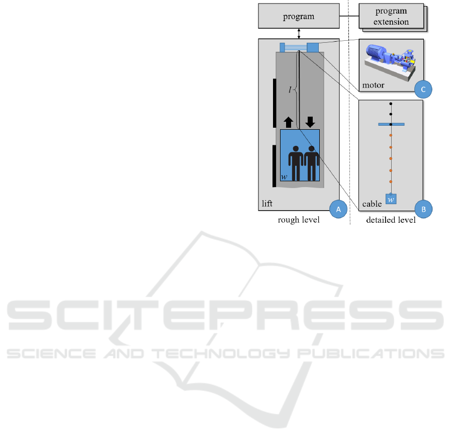
Figure 1 shows the structure of this example.
(A) On the coarse level it consists of a simulation
modelling the structure of the lift and a lift program.
The structure consists of a shaft in which a cabin can
move. The cabin is rigged to a cable. The weight of
the cabin (w) is altered when it stops at one of the
exits. A motor manipulates the length of the cable (l).
The program simulation is connected to the structure
and handles the speed and direction of the motor. In
this setup all parts of the structure are modelled as
rigid bodies. The program has no sensor for l and
positions the cabin only indirectly using the last
position of the cabin and a timer. On this level,
realistic scenarios of use are modelled. An example
of this would be a whole day cycle of an office
building. Most persons want to go up in the morning
and down in the evening. The simulation on this level
is fast.
Figure 1: Structure of the elevator example.
(B) During the development of the lift and its
program the engineers want to investigate, if the
stretching of the cable caused by the weight of the
cabin and the aging of the cable will lead to a wrong
positioning of the cabin. To do this, a detailed but
computationally intensive simulation of the cable is
activated. This simulation is stateful to reflect the
aging of the cable. Only parts of the cable that are
stretched in a particular time step age. If the
misplacement is a problem, the engineer has to
implement an extension to deal with the phenomena
in the program.
(C) After this, the dynamics of the cabin are
investigated closely. A computationally intense
simulation of the motor is activated. This simulation
models the acceleration of the motor and allows to
precisely determine the travel times of the lift. The
simulation is stateful to model the heating of the
motor which influences acceleration. Because the
stretching of the cable is considered irrelevant for this
question, the cable simulation and the corresponding
program extension are deactivated. Because the
program on the coarse level does not account for the
acceleration when calculating the timers, a
corresponding extension must be implemented and
linked to the program.
Note that the program finally deployed needs to
include both extensions.
In both cases, parts of the lift are simulated on two
levels at the same time. This leads to the challenge of
maintaining the consistence between the states of
both levels. If for example in (A) l is increased by
Towards Multi-Level-Simulation using Dynamic Cloud Environments
299
0.1m, all elements of the cable in (B) must be placed
0.1m lower. If in (B) the cable is stretched by 10%,
displacing the lowest point from
-3m to -3.3m, l must be set from 3m to 3.3m in (A).
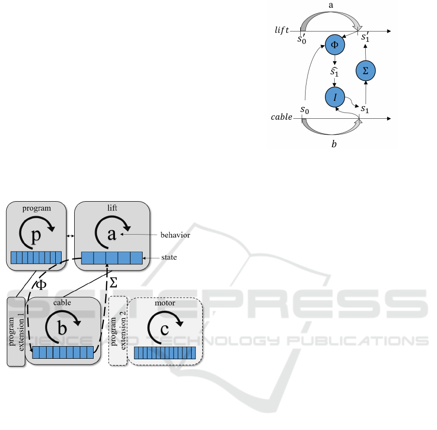
Figure 2 shows a schematic overview of the
example. Each simulation consists of two parts. The
state of a simulation is defined as a valuation of a
fixed set of attributes. The behaviour of a simulation
is defined as a mapping which has this state as input
and produces a new state as output. Applying the
behaviour to a state
of a simulation leads to the
state
. This corresponds to a step in the simulation.
For all simulations the time Δt elapsing in one step is
the same. The coarse simulation of the lift is linked to
a number of detailed simulations. Note that in the lift
example only one of these simulations is connected in
a particular simulation run.
Figure 2: The problem of state synchronisation.
Because the simulation models (i.e. the cable) are
different, the attributes valuated in a state are
different. The states need to be converted between the
simulations. This is done using the state mappings Φ
and Σ. At the current state of our work, these
mappings are given by the modeller. Σ maps the
detailed level state to the coarse level state. It is
typically not reversible, because information is lost.
Referring to the lift example, there are a number of
different positions and age levels of the cable
elements that map to the same l. Φ maps the coarse
level state to the detailed level. In the example, Φ
restores the position of the cable elements using only
l. To do so, Φ has to choose among a possible infinite
set of states that are mapped to l by Σ. To account for
this problem, we propose Φ as a mapping of the
coarse state and the last state of the detailed state.
Figure 3: Execution of the lift example.
Figure 3 gives an overview of the execution of the
example. Note that in general changes on different
levels accrue concurrently, regarding to simulation
time.
Let us consider the lift simulation starts with the
initial state
and the cable simulation with the initial
state
. The states are chosen so that Σ
=
.
This can be seen as that
and
represent ‘the same’
on both levels. Now both simulations step using the
behaviour functions a and b. The cable simulation
ages a number of cable elements, stretching the cable
by 0.1m leading to the state
. In the same time step,
the lift simulation unwinds the cable by 0.2m
according to the initial speed of the motor, leading to
the state
. Converting
to a state of the cable
simulation using Φ results in an intermediate state
.
This state is in conflict to
which was calculated
using the behaviour b of the cable simulation. Simply
overwriting
using
would annihilate the
unwinding of the cable. To avoid this, an integrator
function I must be employed to merge the two states.
The resulting state contains both changes. Using Σ on
this state leads to an integrated state of the lift
simulation that contains again both changes. This
state finally overwrites the state of the lift.
4 CLOUD-DEPLOYMENT
In this section, we describe aspects of deploying
Multi-Level-Simulations in Cloud environments.
Section 4.1 introduces elasticity aspects of Multi-
Level-Simulations. In Section 4.2 we outline our plan
for a dynamic deployment strategy. Finally, in
Section 4.3, we present an initial deployment of our
prototype application.
SIMULTECH 2016 - 6th International Conference on Simulation and Modeling Methodologies, Technologies and Applications
300
4.1 Elasticity in
Multi-Level-Simulations
Multi-Level-Simulations are characterized by their
variable resource requirements depending on the
simulation question. The fluctuations result from the
dynamic nature of Multi-Level-Simulations on two
different layers:
System Level. A Multi-Level-Simulation consists of
multiple components of which not all are operating at
the same time. The entirety of these components
forms the system level. Specifically, in our example
the system consists of program, lift, cable, motor and
the communication component. The required
components vary (a) between different simulation
runs depending on the simulation objective and (b)
within the same simulation run when components
have finished their simulation.
Component Level. The lower level’s complexity of
a simulation is dependent on the simulation
parameters. For example, the cable is one component
of our prototype. While a particular component’s
computational requirements may be low for one run,
it can be higher for another.
In such cases, Cloud Computing can help in
establishing a dynamic infrastructure to scale the
resources in accordance with the simulations’
demand. Ideally, at any point only the required
computing resources will be allocated. Too few
allocated resources (“underprovisioning”) will lead
either to longer runtimes or even abortion of the
simulation. Too many resources
(“overprovisioning”), on the other hand, allow for a
timely execution of the simulation, but at the cost of
dissipation.
4.2 Dynamic Deployment
Contrarily to a static deployment where a fixed set of
resources is allocated at the start of the simulation and
remains allocated throughout its lifespan, a dynamic
deployment is not finished once the required
resources have been allocated and the components
have been installed and launched on it. Instead, a
framework that fulfils the three following tasks needs
to be put in place:
Monitoring. In order to perform runtime adaptations,
the framework needs to collect information about the
simulation resources and components. Specifically,
the utilization of the resources is important to support
a judgement.
Reasoning. Using rules and the data collected by the
monitor, the framework has to perform reasoning
about infrastructure adaptation.
Infrastructure Adaptation. The framework needs to
adapt the infrastructure to the simulation
requirements in both directions, i.e. by reducing or
increasing its size. Also, it needs to adapt the
deployment accordingly.
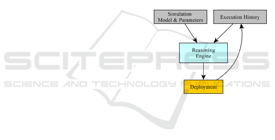
The reasoning pipeline is depicted in Figure 4.
The computational complexity of a simulation
depends on its model as well as its execution
parameters. By combining this with information
about the resource usage it is possible to build an
execution history that serves as input for the
reasoning engine for predicting a suitable deployment
for future simulation runs. For this, we employ
statistical methods that create rules which are
iteratively refined by evaluating their accuracy.
Figure 4: Reasoning Pipeline.
For the monitoring and infrastructure adaptation
tasks we intend to implement an integrated solution
following a models@runtime (Aßmann et al., 2015)
approach and the tools we employed for the initial
deployment. This approach will allow a strong
decoupling of the adaptation logic from the technical
steps necessary for enacting deployment changes.
4.3 Initial Deployment
As an initial approach for a Cloud deployment of our
prototype application we chose a static setup as
depicted in Figure 5.
In this setup, each of the two simulation
components is served by its own virtual machine in
the Cloud. The components exchange status via RMI
and therefore only require a shared network for
communication.
Towards Multi-Level-Simulation using Dynamic Cloud Environments
301
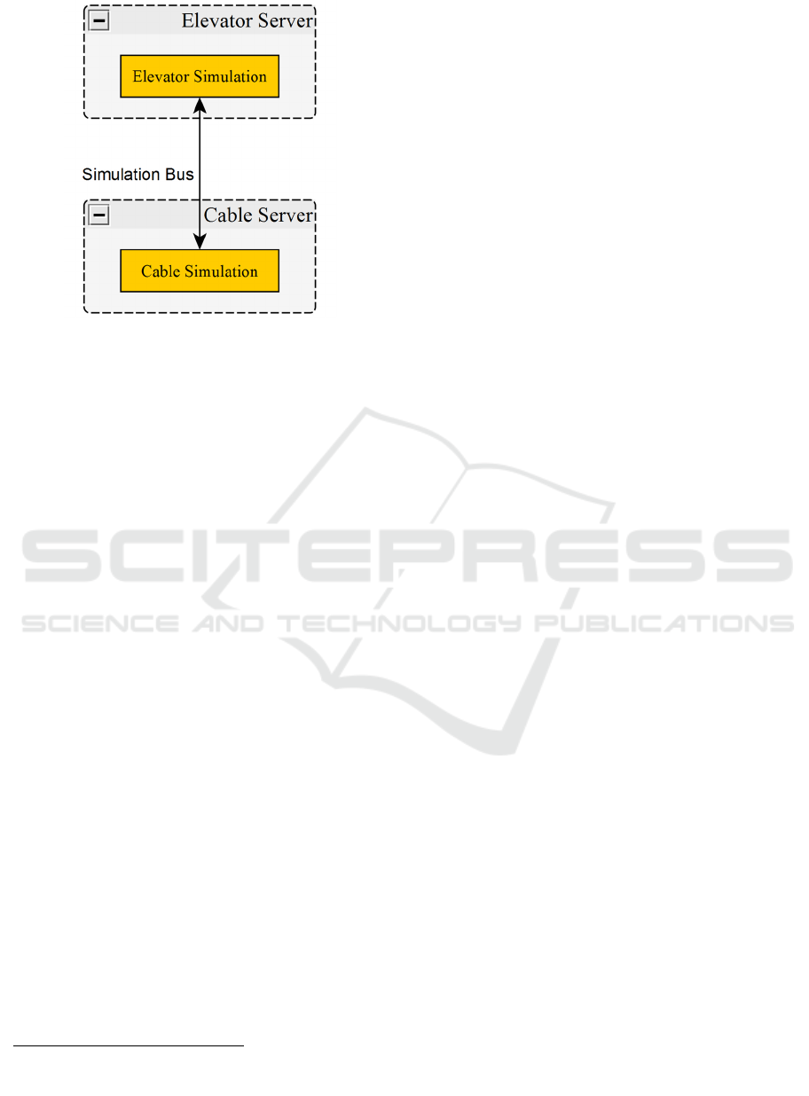
Figure 5: Initial Deployment.
On a technical level, our static deployment is
model-based and agnostic to a particular Cloud
platform. Concretely, we use the TOSCA-based
Cloud orchestration platform Cloudify
1
as well as the
Software Configuration Management tool Ansible
2
.
This allows for a deployment of the simulation on the
variety of Cloud platforms supported by Cloudify as
well as on different operating systems as supported
by Ansible.
We intend to employ the technologies used in the
initial deployment for the dynamic deployment.
5 STATUS AND FUTURE WORK
To get first insights on our concept of Multi-Level-
Simulation and the corresponding Cloud deployment
mechanism, we build a prototype of the described lift
example. The prototype consists of the lift and the
program on the coarse level and the cable on the
detailed level. In the current state of the prototype, the
mappings Φ, Σ and I are hand coded for the example.
First results of this Multi-Level-Simulation are
promising. The simulations stay in synchronisation
and the results of the simulation meet our
expectations.
The deployment of our prototype is distributed,
but currently static. Concretely, the lift and the cable
component are each deployed on their own virtual
machine and the communication between the
components is handled by our prototypical simulation
bus which is based on Java’s RMI. While still in an
early stage, this bus will be capable of handling a
dynamically deployed simulation in the future.
The provided lift example is useful to get first
insights on the correctness of our method, but will be
replaced by a real world example in order to provide
validated results. As a next step, we will connect
proper simulation tools to our prototype and
implement a realistic example. Using hand coded
mapping functions is not ideal in this case. We aim
for a solution that is at least partially automated. To
achieve this, a generic integrator function I, which is
suitable for a variety of Multi-Level-Simulations, is
researched. Employing machine learning algorithms
to generate Φ, Σ seems promising. An input for such
an approach could be a set of scenarios in which the
same happens on both levels.
Another further direction will be the dynamic
activation of detailed simulations at runtime. The
coarse level could be executed on its own, until an
interesting state is reached. The detailed simulation is
connected and is active only as long as needed.
Our next steps with regard to the dynamic Cloud
deployment will include the evaluation of suitable
strategies for the reasoning pipeline. Concretely, we
will evaluate realistic applications built using
simulation tools from the machine tool domain to
extract parameters that are informative for
determining a simulations’ resource requirements.
Then we will assess their accuracy and build an
integrated framework for dynamic deployment.
ACKNOWLEDGEMENTS
We thank the Simulationswissenschaftliches Zentrum
Clausthal-Göttingen (SWZ) for financial support.
REFERENCES
Aßmann, U., Bencomo, N., Cheng, B. H., France, R. B.,
2015. models@runtime (dagstuhl seminar
11481). Dagstuhl Reports, 1(11).
Blochwitz, T., Otter, M., Akesson, J., Arnold, M., Clauss,
C., Elmqvist, H., Friedrich, M., Junghanns, A., Mauss,
J., Neumerkel, D., 2012. Functional mockup interface
2.0: The standard for tool independent exchange of
simulation models.
Claes, R., Holvoet, T., 2009. Multi-model Traffic
Microsimulations, in: Winter Simulation Conference,
WSC ’09. Winter Simulation Conference, Austin,
Texas, pp. 1113–1123.
Dahmann, J. S., Fujimoto, R. M., Weatherly, R. M., 1997.
The Department Of Defense High Level Architecture.
1
Online: http://getcloudify.org/
² Online: https://www.ansible.com/
SIMULTECH 2016 - 6th International Conference on Simulation and Modeling Methodologies, Technologies and Applications
302

Dangelmaier, W., Mueck, B., 2004. Using Dynamic
Multiresolution Modelling to Analyze Large Material
Flow Systems, in: Proceedings of the 36th Conference
on Winter Simulation, WSC ’04. Winter Simulation
Conference, Washington, D.C., pp. 1720–1727.
Eker, J., Janneck, J. W., Lee, E., Liu, J., Liu, X., Ludvig, J.,
Neuendorffer, S., Sachs, S., Xiong, Y., others, 2003.
Taming heterogeneity-the Ptolemy approach. Proc.
IEEE 91, 127–144.
Glaser, F., 2015. Towards Domain-Model Optimized
Deployment and Execution of Scientific Applications
in Cloud Environments. Proceedings of the Doctoral
Symposium at the 5th Conference on Cloud Computing
and Services Sciences (DCCLOSER 2015), Lisbon,
Portugal.
Göttsche, M., 2015. The 8th IEEE International Conference
on Service Oriented Computing & Applications, Rome,
Italy.
Hong, S.-Y., Kim, T.G., 2013. Specification of multi-
resolution modeling space for multi-resolution system.
SIMULATION 89, 28–40. doi:10.1177/003754971
2450361.
Huber, D., Dangelmaier, W., 2011. A Method for
Simulation State Mapping Between Discrete Event
Material Flow Models of Different Level of Detail, in:
Proceedings of the Winter Simulation Conference,
WSC ’11. Winter Simulation Conference, Phoenix,
Arizona, pp. 2877–2886.
Lorido-Botrán, T., Miguel-Alonso, J., Lozano, J. A., 2012.
Auto-scaling Techniques for Elastic Applications in
Cloud Environments. Technical Report: University of
the Basque Country, 11 – 14. doi:10.1145/
2611286.2611314.
Qasha, R., Cała, J., Watson, P., 2015. Towards Automated
Workflow Deployment in the Cloud using TOSCA.
Rao, D. M., 2003. Study of Dynamic Component
Substitutions (Dissertation). University of Cincinnati.
Reynolds, Jr., P. F., Natrajan, A., Srinivasan, S., 1997.
Consistency Maintenance in Multiresolution
Simulation. ACM Trans Model Comput Simul 7, 368–
392. doi:10.1145/259207.259235.
Schütte, S., Scherfke, S., Tröschel, M., 2011. Mosaik: A
framework for modular simulation of active
components in Smart Grids, in: Smart Grid Modeling
and Simulation (SGMS), 2011 IEEE First International
Workshop on. IEEE, pp. 55-60.
Vukojevic-Haupt, K., Karastoyanova, D. Leymann, F.: On-
demand Provisioning of Infrastructure, Middleware and
Services for Simulation Workflows. In: Proceedings of
SOCA 2013.
Towards Multi-Level-Simulation using Dynamic Cloud Environments
303
