
Object Slippage Prevention using Different Control Strategies
Pavel Dzitac
1
, Abdul Md Mazid
2
,
Guy Littlefair
1
and Ashwin Polishetty
1
1
School of Engineering, Deakin University, Geelong, Australia
2
Department of Engineering, Macquarie University, Sydney, Australia
Keywords: Robotic Grasping, Slippage Sensing, Tangential Force Sensing, Slippage Detection, Slippage Prevention,
Incipient Slippage, Grasp Force Estimation, Grasp Force Control.
Abstract: This paper presents experimental results obtained using a friction-based slippage and tangential force
sensing device that has been developed for the purpose of reliable object slippage prevention during robotic
manipulation. The experimental results obtained demonstrate that the developed slippage sensing strategy is
rugged and reliable even in its current “rough prototype” state of development. This work has the potential
to yield a low cost and highly customisable slippage and tangential force sensing device for a variety of
robotic object grasping and manipulation applications. It is envisaged that the work presented here will be
beneficial to researchers in the area of object slippage prevention.
1 INTRODUCTION
Reliable grasping and manipulation incorporates
control decisions that perform better than the basic
“grasp and hold tight” strategies. Adequate grasp
force control is essential to reliable and safe
manipulation; it improves robot’s chances to
manipulate objects autonomously close to optimum
conditions on the first attempt.
Slippage takes place in two stages: incipient
slippage and bulk or gross slippage (Tremblay and
Cutkosky, 1993). It is characterised by a mechanical
behaviour known as “stick-slip” that results in
vibration and is present during relative motion
between two surfaces in contact (Bowden and
Tabor, 1986). In order to prevent slippage it is
necessary to predict what researchers call pre-slip
(Petchartee and Monkman, 2007) or incipient slip
(Bowden and Tabor, 1986), (Mingrino et. al, 1994,
Canepa et al., 1994, Pelossof et al., 2004), the tell-
tale sign that slippage is about to occur. Predictive
measures such as incipient slip detection have been
used by researchers to control slippage during object
manipulation (Canepa et al., 1994, Pelossof et al.,
2004, Dubey and Crowder, 2006, Watanabe and
Obinata, 2007).
The stick-slip vibration frequency and amplitude
are dependent on many factors and are not a constant
behaviour during slippage under all conditions;
vibration frequency and amplitude vary with object
materials, different surface conditions and speed
(Bowden and Tabor, 1986, Abdo et al., 2009). Stick-
slip can be reduced under certain conditions by
applying a particular range of vibration frequencies
at specific amplitudes to the system that produces
the stick-slip induced vibration (Abdo et al., 2009).
It may also be challenging to distinguish stick-slip
vibration from background noise. Therefore, it could
be concluded that stick-slip is not an ideal source for
generic incipient slippage detection, but it is a
mechanical behaviour by which most slippage
events can be detected using vibration detection
techniques.
Researchers have developed many tactile sensors
intended for grasp force and slippage control
(Russel, 1990, Choi et al., 2005, Rossiter and Mukai,
2005, Dahiya et al., 2010). Industrial robotics
applications require sensors that can handle
significant loads; a load of 50 N is towards the low
end on the load scale. Therefore load bearing
capacity and the ability to maintain sensitivity at
maximum load are important criteria that determine
the suitability of a sensing technology for industrial
robotics applications.
This paper presents experimental results obtained
with the latest friction-based slippage and tangential
force sensing prototype, in conjunction with various
slippage detection and prevention strategies.
The working principle of the friction-based
slippage sensing device is described in (Dzitac and
Dzitac, P., Mazid, A., Littlefair, G. and Polishetty, A.
Object Slippage Prevention using Different Control Strategies.
DOI: 10.5220/0006003505590566
In Proceedings of the 13th International Conference on Informatics in Control, Automation and Robotics (ICINCO 2016) - Volume 1, pages 559-566
ISBN: 978-989-758-198-4
Copyright
c
2016 by SCITEPRESS – Science and Technology Publications, Lda. All rights reserved
559
Mazid, 2012), and is briefly summarised here to
facilitate understanding.
2 FRICTION-BASED SLIPPAGE
SENSING
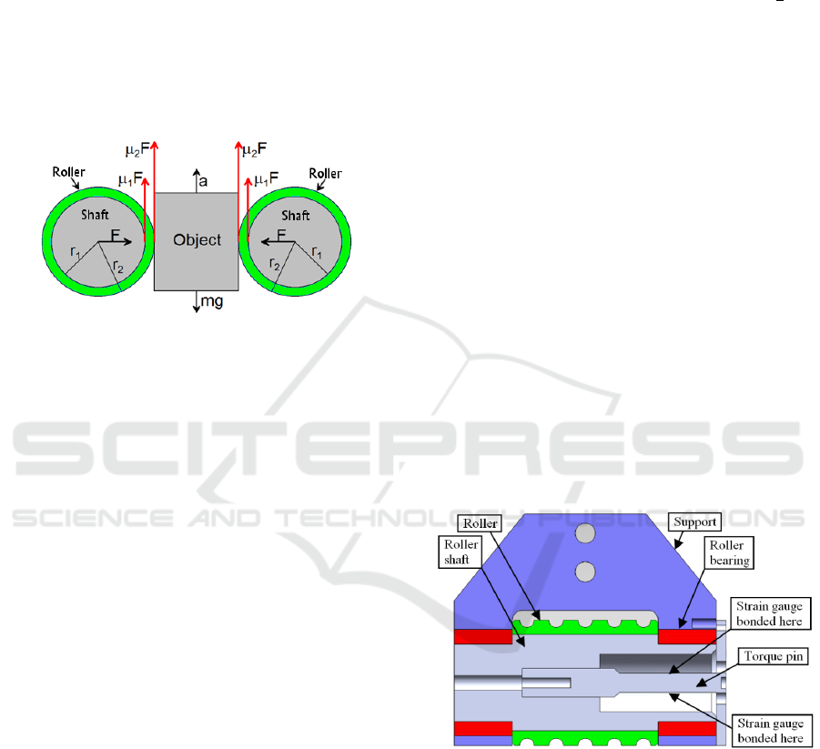
The slippage sensing device relies on friction
between two sets of friction surfaces: one at the
roller-shaft interface, and the other at the roller-
object interface (Figure 1).
Figure 1: Friction-based parallel jaw gripper concept with
rollers on support shaft.
When the applied grasp force to the object is
insufficient, the roller slips on its support shaft, but
still rolls on the surface of the manipulated object.
This allows the static coefficient of friction to be
maintained at the roller-object interface. Therefore,
this design incorporates the following benefits.
• Slippage starts at the roller-shaft interface well
before slippage at the gripper-object interface,
which facilitates object slippage prevention;
• The static and dynamic coefficients of friction at
the roller-shaft interface are known in advance,
which allows adequate grasp force application
when object mass is known.
In Figure 1 the friction force between the roller and
its support shaft is given by
F
= µ
F
(1)
Where, µ
is the coefficient of friction at the roller-
shaft interface and F is the grasp force.
The friction force between the roller and the
object prevents roller slippage on the object surface
and is given by
F
= µ
F
(2)
Where, µ
is the coefficient of friction at the roller-
object interface.
The net torque at the roller-shaft interface is given
by
=
r
−
r
,
≤
(3)
Where,
represents the tangential force during
grasping. Slippage at the shaft-roller interface will
begin when the net torque
>0
.
When both friction rollers are holding the object,
the weight of the object will be shared between the
two rollers such that each roller will support
.
In general, a smaller net torque
will require a
smaller grasp force to prevent slippage at the roller-
shaft interface. This simple design concept allows
slippage between the roller and the manipulated
object to be prevented reliably.
3 TORQUE (TANGENTIAL
FORCE) SENSOR DESIGN
The prototype parallel gripper incorporates two
sensing elements, one for tangential force sensing
and one for slippage sensing, each fitted to a parallel
gripper jaw. The torque sensing element (Figure 2)
is fitted with a full Wheatstone bridge torque sensor
that senses the tangential force developed on the
shaft by the weight of the object held in the gripper.
The roller rotates on the shaft, which in turn is
supported on roller bearings at its two ends to
minimise friction and allow the full torque that is
developed on the roller by the object to be sensed by
the torque pin that is bolted to the support.
Figure 2: Cross-section through the torque sensing
element assembly.
The TML QFCT-2 strain gauges used for the
torque pin’s full Wheatstone bridge have the
following parameters:
• Gage factor GF = 2.12 +/-1 %
• Grid length = 2 mm
• Allowable strain = 3 %
The 3 % strain allows a strain gauge elongation of
2mm∗0.03=0.06mm=60μm
ICINCO 2016 - 13th International Conference on Informatics in Control, Automation and Robotics
560
Due to the very small values, strain is also
expressed in “microstrain” (strain * 10
6
). In this case
the 3 % strain limit of the strain gauge can be
expressed as
0.03∗10
=30,000microstrain
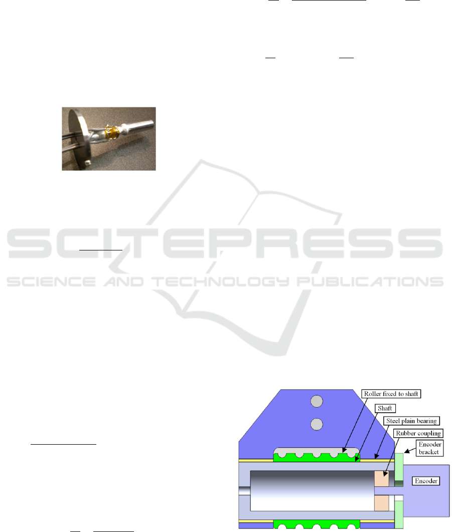
The torque pin (Figure 3) was designed to
maximise its torsional strain when a 300 gram load
is held in the gripper. It is made of 6061-T6
aluminium, has a diameter of 4 mm and a length of
20 mm. The design intent was to make the pin
diameter as small as possible to maximise its strain
under the given load (and therefore the torque
resolution) but still allow the strain gauges to be
fitted on its circumference without overlap.
Figure 3: Torque pin assembly fitted with a full
Wheatstone bridge.
The maximum torque strain for a round shaft is
given as
γ
=
4T
π
∗E∗R
(
1+υ
)
(4)
Where,
γ
- maximum shaft torsional strain
T - Applied torque to shaft
E – Elastic modulus of shaft material
R – Shaft (pin) outer radius
υ – Poison ratio
The design parameters for the torque pin are as
follows:
T=3N*0.013m=0.039Nm
E=68.9*109N/mm
2
R=0.002m;
υ=0.33
Substituting the parameters in equation 4 gives
γ
∗.
∗.∗
∗.
∗
(
.
)
∗
The 120 microstrain range is well within the
allowable 30,000 microstrain that can be applied to
the strain gauge without causing it damage.
The theoretical full bridge output, not accounting
for losses is estimated as
E
E
=
GF∗
γ
2
(5)
Where,
E
0
-bridgeoutput(mV)
E
i
-bridgeexcitation(V)
GF–thegaugefactorofthestraingauge
Substituting in equation 5 gives a bridge output of
E
E
=
2.12∗120∗10
2
=0.127
mV
V
At full strain and an excitation voltage of 5 V DC
the theoretical bridge output is
E
E
@5V=0.127
mV
V
5V=0.635mV
The bridge output is expected to vary from the
theoretical value due to variations in excitation
voltage, variations in strain gauge extension wire
resistance and because the strain gauge is not
matched to aluminium for temperature
compensation. These variations from the theoretical
output will be relatively small (within 5 %),
therefore acceptable for measuring the tangential
force developed by the object on the robot gripper.
4 SLIPPAGE SENSOR DESIGN
The second jaw of the slippage sensing device was
fitted with an incremental rotary encoder designed to
sense roller rotation when the object slips in the
gripper. In this design the steel roller support shaft is
press-fitted into the aluminium roller such that they
rotate together. The shaft can rotate in the steel plain
bearings (Figure 4). The encoder is attached to the
support using a screw, and its shaft is coupled to the
roller support shaft via a silicone rubber disc. This
allows the encoder to sense relative motion between
the roller support shaft and the steel plain bearings,
therefore allowing slippage to be detected by the
same principle as described in section 2 above.
Figure 4: Cross-section through the slippage sensing
element assembly.
Object Slippage Prevention using Different Control Strategies
561
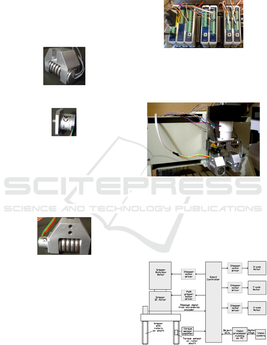
5 EXPERIMENTAL SETUP
The major components of the experimental setup are
shown in Figure 5 to Figure 9. The schematic
representation of the experimental setup is shown in
Figure 10.
Figure 5: Friction-based tangential force sensing device
fitted with torque sensor.
Figure 6: Nemicon 18S-500-2MC-2-15-00E incremental
encoder, used as slippage sensor.
Friction-based slippage sensing roller assembly
is fitted with the Nemicon incremental encoder. The
rubber O-rings are used to increase the coefficient of
friction and provide mechanical compliance between
the gripper and the grasped object. The O-rings also
increase resistance to object rotation in the gripper
due to the discrete contact points formed with the
object (Dzitac et al., 2014).
Figure 7: Encoder fitted to the roller assembly.
The Windows 7 operating system, running on an
Asus notebook and executing custom vision
software, processes the image received from the
Basler vision camera to determine object shape, size,
location and orientation. Object data is sent to the
Moacon controller via an RS232 communication
link. The Moacon C programmable controller (with
digital inputs, relay outputs, analog inputs,
quadrature encoder inputs, pulse width modulation
PWM outputs and four position controllers for the
XYZ and R stepper motor drivers) runs custom
software that performs signal processing, motion
planning, instinctive control, motion control and
robot control at a basic level.
Figure 8: Moacon controller.
XYZ+R Cartesian robot (“R” stands for gripper
rotation around Z axis) fitted with a modified
Schunk RH701 electric gripper to allow higher grasp
forces to be applied. This allows a 300 g object to be
held safely without overstressing the gripper.
Figure 9: Cartesian robot fitted with gripper, slippage
sensing element and tangential force sensing element.
Other experimental setup components include the:
• Full bridge amplifier model TWL-9R92 for
torque sensor strain gauges;
• G251X digital stepper motor driver for XYZ and
R axes;
• MD10C brush motor PWM drive for grasp force
control.
Figure 10: Schematic representation of the experimental
setup using the final friction-based gripper design – the
vision camera is used to find the object.
ICINCO 2016 - 13th International Conference on Informatics in Control, Automation and Robotics
562
Three sets of experiments were conducted to assess
different slippage control strategies:
• Experiment 1 – Simple slippage control;
• Experiment 2 – Sensor fusion based slippage
control;
• Experiment 3 – Proportional based slippage
control.
A 300 gram aluminium object was used for the
experiment (Figure 11). The robot was instructed to
execute the following tasks autonomously:
• Grasp the object with approximately 10 % of the
available grasp force;
• While lifting the object, adjust the grasp force to
stop slippage;
• When object lifting is completed accelerate the
gripper downward then upward and
monitor/control slippage;
• If slippage becomes large and potentially
uncontrollable (i.e. there is not enough grasp
force available to control slippage), stop robot
motion and revert to manual robot control by a
human to prevent damage;
• Else move gripper down and release the object.
Constraints and assumptions:
• Object shapes were limited to rectangular and
cylindrical;
• Object mass was limited to approximately 300
grams to avoid overstressing the gripper;
• The object was assumed to be capable of
sustaining 100 % grasp force without damage;
• The roller was assumed to always rotate when object
slippage occurred. The term “object slippage” is used
here to mean slippage at the roller-shaft interface not
at the roller-object interface;
Initial grasp force creates sufficient contact with
the object to cause the roller to rotate when object
lifting begins.
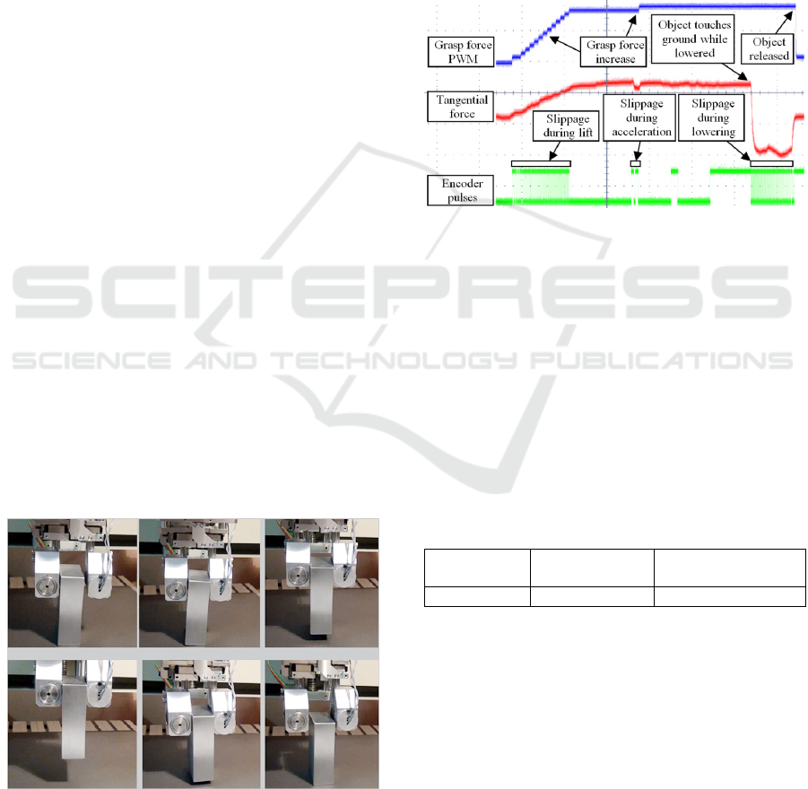
Figure 11: Object grasping, lifting and releasing sequence
using the prototype slippage and tangential force sensing
device.
5.1 Experiment 1 Results – Simple
Slippage Control
The simple slippage control strategy requires the
robot to apply an initial grasp force of 10 % and then
increment the grasp force by 5 % when slippage is
detected. Grasp force is estimated from the
percentage of the pulse width modulated (PWM)
current applied to the gripper motor. Figure 12
shows the grasp force, tangential force and slippage
sensing encoder pulses recorded during the grasp
and manipulation cycle using this control strategy.
Figure 12: Initial grasp force set at 10 % of range. Grasp
force increments are in steps of 10 %. The oscilloscope
horizontal time scale is 2 s/division. Slip during
acceleration is about 0.25 mm (i.e. roller rotates 1.44 ° on
its Ø20 mm support shaft).
Unpredicted slippages were recorded in each of
the ten object manipulation attempts. However, all
unpredicted slippages were successfully resolved by
increasing the grasp force and stopping the slippage,
partially due to the medium manipulation velocity of
approximately 1 m/s.
The results for the simple slippage control
strategy are summarised in Table 1.
Table 1: Results for simple slippage control strategy.
Total object
lifts
Unpredicted
slippage
Slippage stopped
successfully
10 10 10
5.2 Experiment 2 Results – Sensor
Fusion Slippage Control
This experiment was conducted using the same
hardware, methodology and constraints as in
Experiment 1 above, except that the “sensor fusion”
slippage control strategy (Dzitac et al., 1014) was used
here. The diagram in Figure 13 illustrates the grasp
force control algorithm used; sensor fusion determines
whether slippage is “potential”, “controllable” or
Object Slippage Prevention using Different Control Strategies
563
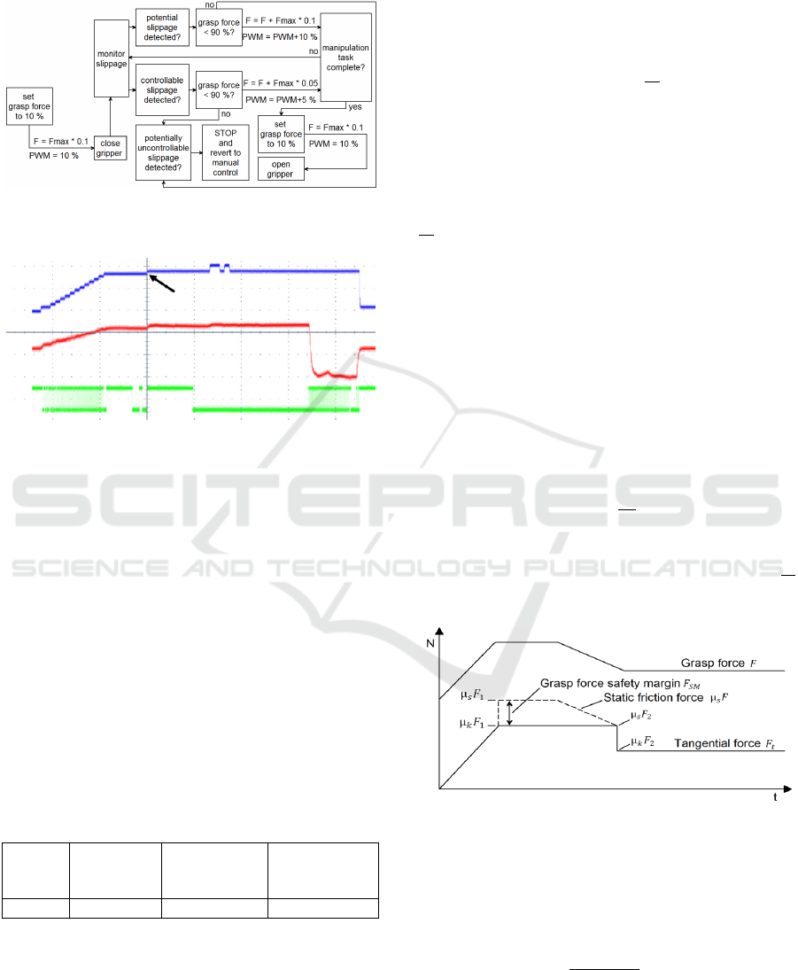
“potentially uncontrollable”. The recorded grasping
and manipulation data is shown in Fig. 14.
Figure 13: Grasp force control state diagram including
sensor fusion based slippage detection.
Figure 14: Unpredicted slippage occurred during lifting
but was stopped by increasing grasp force.
Table 2 summarises the experimental results. One
unpredicted slippage occurred during the initial lift of
the first attempt. Two unpredicted slippages also
occurred due to a “creep” effect noticed during
experimentation. Because the encoder tracks the roller
displacement over time, small slippages accumulate
until it is sufficient to trigger a slippage event, which
is defined as > 4 encoder counts. This behaves like a
slippage integrator; however when a slippage event is
triggered as a result of slippage creep, the grasp force
increase stops slippage, but the sensor fusion strategy
in its current form cannot predict the slippage because
the changes in tangential force are too small to trigger
a controller reaction.
Table 2: Results for sensor fusion slippage control
strategy.
Total
object
lifts
Unpredicte
d slippage
Slippage due
to “creep”
Slippage
prevented
successfully
10 1 2 7
5.3 Experiment 3
Results – Proportional Slippage
Control
This experiment was conducted using the same
hardware, methodology and constraints as in
Experiments 1 and 2 above, except that the
performance of a modified version of the slippage
control strategy was compared to the performance of
the sensor fusion grasp force control strategy.
This strategy uses the ratio of the static to the
dynamic coefficient of friction
as a scaling factor
for grasp force correction that depends on the values
of the two coefficients of friction at the roller-shaft
interface where slippage occurs first. The reasoning
behind this strategy is that the additional grasp force
required to stop “object slippage” (i.e. slippage at
the roller-shaft interface) will be proportional to the
ratio at the roller-shaft interface and can be
illustrated as follows.
Let μ
F
in Figure 15 be the grasp force at which
slippage stops during object lifting and μ
F
the
static friction force when slippage stops. If the grasp
force is then reduced to the point of incipient
slippage (i.e. the natural grasp force safety margin
F
=0), the reduced static friction becomes μ
F
and results in the following relationship
μ
F
=μ
F
(6)
Re-arranging gives
F
=F
μ
μ
(7)
Therefore, at the instant when slippage starts F
(i.e.
the grasp force) has to be increased by at least the
ratio to stop slippage successfully.
Figure 15: Grasp force reduction to the point of roller
slippage on shaft.
The proposed grasp force control strategy in this
case (when no slippage takes place) can be
expressed as follows
F=F
1+
|
F
−F
|
F
,F
>0
(8)
Where,
• F is the total grasp force applied to the object;
ICINCO 2016 - 13th International Conference on Informatics in Control, Automation and Robotics
564
• F
is the grasp force recorded at the point where
slippage stopped while lifting the object; it is
the static component of the total grasp force;
• F
is the tangential force recorded at the point
where slippage stopped while lifting the object;
• F
is the current tangential force developed by
the grasped object on the roller;
•
|
F
−F
|
is the absolute value of the tangential
force change;
• F
|
|
is the dynamic component of the
total grasp force; its value changes in
proportion to changes in F
relative to F
.
When slippage signals are detected, the static
component F
is assigned a new value that has been
incremented by a factor
, which allocates a grasp
force safety margin proportional to the friction
characteristics at the roller-shaft interface. This
increases the static components of the grasp force
safety margin to prevent future slippage and can be
expressed as follows
F
=F
μ
μ
(9)
The grasp force control in equation 8 can also be
expressed in terms of PWM duty as follows
PWM=P
W
M
1+
|
F
−F
|
F
,F
>0
(10)
Where,
• PWMisthepulsewidthmodulationduty
appliedtothegrippermotor;itcontrolsthe
graspforceofthegripper;
• PWM
isthepulsewidthmodulationrecorded
atthepointwhereslippagestoppedwhile
liftingtheobject;
• PWM
|
|
isthedynamiccomponentof
thetotalgraspforce;itsvaluechangesin
proportiontochangesinF
relativetoF
.
When slippage is detected, PWM
will be assigned a
new value that has been increased by the
factor as
follows
PWM
=PWM
μ
μ
(11)
Equation 11 is useful because most controllers are
equipped with PWM outputs that can be used to
control the grasp force of a robot gripper.
To improve the initial grasp-lift time and the
overall reaction to slippage, a rate-based grasp force
safety margin control strategy was used as a
replacement for equation 11. When slippage is
detected PWM
is increased based on the rate of
received encoder pulses (i.e. rate of slippage).
PWM
=PWM
+ks
(12)
Where,
• k is a gain constant and s is the slippage rate
within a control loop cycle (e.g. number of
encoder pulses in 100 ms).
This rate-based slippage control is possible because
the rate of slippage is readily available from the rate
of the encoder pulses generated during slippage.
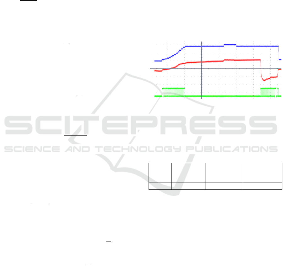
The recorded grasping and manipulation data is
shown in Figure 16.
Figure 16: Slip-rate based control during initial lifting and
“proportional” control after initial lifting.
Table 3 summarises the experimental results for
the rate-based grasping and manipulation
experiment.
Table 3: Results for proportional slippage control strategy.
Total
object
lifts
Unpredicte
d slippage
Slippage due
to “creep”
Slippage
prevented
successfully
10 2 2 6
6 CONCLUSION AND FUTURE
WORK
The addition of torque sensing to one gripper roller
made it possible to use preventive slippage control
strategies such as sensor fusion and proportional
control, which is not possible when using a slippage
sensor alone.
The slippage prevention strategies based on
sensor fusion and proportional control used in these
experiments perform better that basic slippage
control strategy that increases grasp force after
slippage is detected. However, unpredicted slippage
still occurred due to the “slippage creep” effect
inherent in the current design. An unpredicted
Object Slippage Prevention using Different Control Strategies
565

slippage is considered to be a slippage event to
which the control strategy did not react before the
actual slippage was detected.
The current tangential force sensing prototype is
affected by hysteresis due to stray friction in the
mechanical assembly. Future work could be done to
reduce or eliminate stray friction.
A derivative term could be added to the
proportional term of the proportional controller to
facilitate reaction to tangential force rate of change,
and as a result improve slippage prevention.
The developed slippage detection and control
strategy can sense slippage and tangential force in
one axis only. Further work can be done to add
slippage sensing in other axes.
The slippage control strategy presented here is
not a generic solution for slippage control in robotic
object manipulation, but is rugged, reliable,
repeatable and highly customizable.
REFERENCES
Tremblay M. R., Cutkosky M. R., 1993. “Estimating
Friction Using Incipient Slip Sensing During a
Manipulation Task,” In Proceedings of IEEE
International Conference on Robotics and
Automation, Atlanta (GA).
Bowden F. P., Tabor D., 1986. The Friction and
Lubrication of Solids, UK: Oxford Science Press.
Petchartee S., Monkman G., 2007. “Pre-slip detection
based Tactile Sensing,” In Proceedings of
International Conference on Sensors, Sensor
Networks and Information, Toulouse.
Mingrino A., Bucci A., Magni R., Dario P., 1994.
“Slippage Control in Hand Prostheses by sensing
Grasping Forces and Sliding Motion,” In Proceedings
of the IEEE/RSJ International Conference on
Intelligent Robots and Systems.
Canepa G., Campanella M., Rossi D., 1994. “Slip
Detection by a Tactile Neural Network,” In
Proceedings of IEEE/RSJ Internationl Conference on
Intelligent Robots and Systems.
Pelossof R., Miller A., Allen P., Jebara T., 2004. “An
SVM Learning Approach to Robotic Grasping,” In
Proceedings of International Conference on Robotics
and Automation.
Dubey V. N., Crowder R. M., 2006. “A dynamic tactile
sensor on photoelastic effect,” Sensors and Actuators,
no. 128, pp. 217-224.
Watanabe N., Obinata G., 2007. “Grip Force Control
Based on the Degree of Slippage Using Optical Tactile
Sensor,” In International Symposium on Micro-
NanoMechatronics and Human Science.
Abdo J., Tahat M., Abouelsoud A. A., 2009. “The effect
of excitation frequencies on stick-slip amplitude,” In
Proceedings of International Conference on Integrity,
Reliability and Failure, Porto (Portugal).
Russel R. A., 1990. Robot Tactile Sensing, New York:
Prentice Hall.
Choi B., Cho H. Kang R., S., 2005. “Development of
tactile sensor for detecting contact force and slip,” In
Proceedings of IEEE/RSJ International Conference on
Intelligent Robots and Systems, Edmonton.
Rossiter J., Mukai T., 2005. “A Novel Tactile Sensor
Using a Matrix of LEDs Operating in Both
Photoemitter and Photodetector Modes,” In
Proceedings of 2005 IEEE Conference on Sensor.
Dahiya R. S., Metta G., Valle M., Sandini G., 2010.
“Tactile Sensing - From Humans to Humanoids,”
IEEE Transactions on Robotics, vol. 26, no. 1.
Dzitac P., Mazid A. M., 2012. “A method to control grip
force and slippage for robotic object grasping and
manipulation”, In MED 2012 Proceedings of the
Control and Automation Mediterranean conference,
Barcelona, Spain. pp. 116-121.
Dzitac P., Mazid A. M., Littlefair G., Polishetty A., 2014.
“The Effective Radius and Resistance to Slippage”, In
Proceedings of the 11th International Conference on
Informatics in Control, Automation and Robotics
(ICINCO 2014), Vienna, Austria.
Dzitac P., Mazid A. M., Littlefair G., Polishetty A., 2014.
“Robotic Grasping and Manipulation Controller
Framework - Architecture Redevelopment”, In
Proceedings of the 11th International Conference on
Informatics in Control, Automation and Robotics
(ICINCO 2014), Vienna, Austria.
ICINCO 2016 - 13th International Conference on Informatics in Control, Automation and Robotics
566
