
A Novel Strut-type Modular Robotic Structure using Rigid Node
Weibing Li, Robert C. Richardson and Jongrae Kim
School of Mechanical Engineering, University of Leeds, LS2 9JT, Leeds, U.K.
Keywords:
Modular Robots, Rigid Nodes, Central Pattern Generators, Distributed Control, Physics-based Simulation.
Abstract:
This paper proposes a novel way of constructing strut-type modular robotic structures to avoid some diffi-
culties of designing and implementing ideal compliant nodes. Rigid nodes are employed to replace the ideal
compliant nodes and to reduce the structural complexity while the feasibility of hardware implementation
is dramatically improved. To release some kinematic constraints caused by the rigid nodes, we introduce
robotic struts that consist of two prismatic actuators linked by a passive revolute joint. Physics-based robot
models are constructed using a robot simulator. A scalable distributed control method is implemented using
coupled central pattern generators. And, for comparison, the same control method is applied to conventional
and the proposed strut-type modular robotic structures. Simulation results show that the proposed strut-type
structures have several advantages over the conventional ones including less number of passive joints and
shape-maintenance property.
1 INTRODUCTION
A modular robotic structure (MRS) consists of sep-
arate identical or different modules that can attach
to or detach from each other to make the whole
robot achieve manual or self-adaptive reconfiguration
(Yim et al., 2007). One outstanding characteristic of
MRSs is their shape-changing capability. In modular
robotics, the following two shape-changing methods
have been widely studied:
• Reconfiguration: an MRS can change its configu-
ration (i.e., connectivity) by attaching and detach-
ing robotic modules manually or self-adaptively.
• Deformation: an MRS with a specific configura-
tion can change its shape without changing the
connectivity of robotic modules.
Reconfiguration endows an MRS with a wide range
of robotic structures which can emulate conventional
monolithic robots and are suitable for different tasks
under different working environments. Being differ-
ent from reconfiguration, deformation can be used to
adjust the MRS shape to internal and external forces
exerted on the robotic structure.
To utilize the benefits generated from reconfigu-
ration and deformation, numerous MRSs have been
designed and developed. Most of the existing MRSs
have block-like modules fitted with only revolute ac-
tuators (Zhang et al., 2003; Kurokawa et al., 2006;
Østergaard et al., 2006; Salemi et al., 2006; Yim
et al., 2007; Spr¨owitz et al., 2014), which are suit-
able for reconfiguration. Relatively less attention is
given on strut-type MRSs using prismatic actuators
(Curtis et al., 2007; Lyder, 2010; Yu, 2010; Zagal
et al., 2012), which are adept at deformation. A de-
sign case of using both prismatic and revolute actu-
ators can be found in (Baca et al., 2014). Usually, a
revolute actuator can only rotate around its axis, while
a prismatic actuator can elongate its body to reach
some positions in the workspace directly. Prismatic
actuators can form parallel truss-based structures that
provides inherent stability. Hence, prismatic actuators
may be more suitable for industrial activities such as
load transportation than revolute actuators (Ramchurn
et al., 2006).
In recent years, researchers have designed differ-
ent strut-type MRSs using prismatic actuators for in-
vestigating their deformation and locomotion capa-
bilities. Ideally, a strut-type MRS should have an
ideal node connector mechanism which can connect
numerous robotic struts. More importantly, robotic
struts can rotate around the node center with some
passive three degrees-of-freedom spherical joints and
robotic struts connected by a same node should have a
common center of rotation. In most simulations of the
existing literature, robotic struts are jointed by point-
like ideal nodes. Such point-likeideal nodes is helpful
to reducing the complexity of kinematics (Hamlin and
Sanderson, 1998) and providing compliant capability
for strut-type MRSs, however, physical implementa-
Li, W., Richardson, R. and Kim, J.
A Novel Strut-type Modular Robotic Structure using Rigid Node.
DOI: 10.5220/0006004502610268
In Proceedings of the 13th International Conference on Informatics in Control, Automation and Robotics (ICINCO 2016) - Volume 1, pages 261-268
ISBN: 978-989-758-198-4
Copyright
c
2016 by SCITEPRESS – Science and Technology Publications, Lda. All rights reserved
261

tion of such ideal nodes is highly difficult and even
impossible (Lyder, 2010).
A lot of efforts have been made to design and
implement an ideal compliant node. In the Tetrobot
project (Hamlin and Sanderson, 1998), a centric
multilink spherical (CMS) joint mechanism was de-
signed, which can let the extended lines of its con-
nected struts intersect at a same point. Such a CMS
joint design can not only make a homogeneousdesign
of Tetrobot possible but also simplify the kinematics
of structures. However, CMS joint cannot be used to
form chain-type structures. Additionally, CMS joints
tend to become too weak to sustain a massive robotic
structure. Moreover, the Tetrobot is hard to reconfig-
ure as adding or removing struts usually need to dis-
assemble the whole robotic structure (Lyder, 2010).
A workaround for constructing strut-type MRSs
is to use struts that have their own center of rotation
on the node surface. In such a solution, ball-and-
socket joints and universal joints are commonly em-
ployed. In (Yu, 2010; Lyder, 2010), passive ball-and-
socket joint based designs were adopted to provide
compliant movements. Another well-known connec-
tor mechanism is the one designed by NASA for a
12-tetrahedron (12-TET) robot (Curtis et al., 2007).
Specifically, NASA researchers developed two types
of connectors, one is a wheel-shaped node for loco-
motion and the other one is a special payload node.
The nodes endow itself with compliant flexibility by
using passive universal joints. It is worth pointing out
that the above non-ideal compliant nodes do simplify
the physical implementation but make the kinematic
analysis more complex (Lyder, 2010). This may be
the reason why prototypes (e.g., Odin and 12-TET
modular robots) using such compliant nodes are diffi-
cult to control and can only complete simple locomo-
tion and/or deformation tasks.
Apart from the node design, another challenge
in modular robotics is to construct a unified control
framework that is both suitable to different modu-
lar robotic systems and scalable to robot size. Due
to the modularity of modular robots, distributed con-
trol methods are intrinsically more scalable than cen-
tralized control methods. The scalability of a phase-
automata based distributed control method developed
for chain-type PolyBot modular robots has been val-
idated by using a physical snake robot with 55 mod-
ules (Zhang et al., 2003). In (Yu, 2010), a scalable
control framework for realizing coordinating locomo-
tion of amorphous MRSs was established, analyzed
and verified. Such a scalable control framework is
based on a central pattern generator (CPG) based dis-
tributed control method.
Based on the above understanding, we focus on
using rigid nodes for constructing strut-type MRSs
to avoid the difficulty of implementing ideal com-
pliant nodes. Unlike passive compliant nodes, struts
connected using rigid nodes can not rotate passively
around the nodes. Rather, by connecting struts rigidly
using rigid nodes, the extended lines of struts intersect
at a same point, which simplifies the kinematics com-
plexity. To release some kinematic constraints caused
by using rigid nodes, we use robotic struts that are
comprised of two prismatic actuators linked by a pas-
sive revolute joint. For validating the proposed way of
constructing strut-type MRSs, a scalable distributed
control method is developed inspired by (Yu, 2010).
This paper is organized as follows: firstly, a novel
strut-type modular robotic structure is presented; sec-
ondly, a control method using central pattern gen-
erator is designed based on a moving principle of
which the performance is demonstrated by a proto-
type; thirdly, locomotion and deformation capabilities
are verified by simulations; and finally, conclusions
are presented.
2 ROBOTIC STRUCTURE &
CONTROL
In this section, a novel strut-type MRS is to be intro-
duced and details about the robot modeling and con-
troller development environments including a CPG
control method are to be presented.
2.1 Strut-type MRSs
Two strut-type MRSs are illustrated: one is conven-
tional MRSs using ideal nodes and the other one is
the proposed MRSs using rigid nodes. Figure 1(a)
shows a conventional square-shaped MRS of which
each strut has two prismatic actuators. The four
robotic struts are connected using ideal compliant
nodes equipped with passive revolute joints. Hence,
the struts jointed by the same node can rotate around
a common center of rotation. Each revolute joint has
a rotation range of 80 degrees (Yu, 2010). As men-
tioned before, such ideal nodes are very difficult to
design and implement. To avoid this implementation
difficulty and reduce the kinematics complexity, rigid
nodes are proposed for connecting robotic struts as
shown in Figure 1(b).
Besides, differing from conventional struts that
only have prismatic actuators, each strut is comprised
of two prismatic actuators and one revolute actua-
tor. To release the kinematic constraints introduced
by rigid nodes, we let the revolute actuator be passive
to add compliance for MRSs. To the authors’ best
ICINCO 2016 - 13th International Conference on Informatics in Control, Automation and Robotics
262
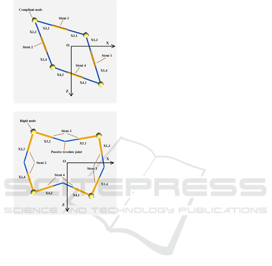
(a) A square robot with ideal compliant nodes.
(b) A square robot with rigid nodes.
Figure 1: Square robots with compliant and rigid nodes.
knowledge, such a hybrid strut design has never been
investigated and reported in the literature. Consider-
ing the type of actuators and joints used within each
strut of the square robots, for convenience, hereafter,
we term the robots shown in Figure 1(a) and (b) as
RPPR (with R and P separately representing revolute
and prismatic actuators) and PRP square robots, re-
spectively. For constructing more complex structures,
we consider each square robot as a meta-module,
then arbitrary robotic structures can be constructed by
rigidly connecting such square meta-modules.
To obtain movements of a robotic strut, one can let
the two connected nodes work alternatively as a fixed
anchor resorting to a friction-changing mechanism on
the node bottom (Cheng et al., 2010). In this paper,
to prevent from designing a friction-changing mech-
anism, we use the following moving steps to achieve
a worm-like locomotion of a robotic strut with two
prismatic actuators (Yu, 2010):
• Step 1: extend one of the prismatic actuators and
keep the other one still;
• Step 2: retract the fully extended prismatic actua-
tor and extend the other one simultaneously;
• Step 3: retract the fully extended prismatic actua-
tor and keep the other one still.
For better understanding, we have tested such a mov-
ing principle using a physical strut controlled by an
Arduino Uno board. Figure 2 shows the experimental
test results. Initially, the prismatic actuators are fully
retracted. Then, following the abovemoving steps pe-
riodically, the robotic strut can obtain a worm-like lo-
comotion due to the change of its mass center during
the task execution process.
Remarks. As illustrated in Figure 3, initially, the
robotic strut keeps still and the normal forces N
1
and N
2
as well as the gravity force G should satisfy
N
1
+ N
2
= G and N
1
= N
2
= G/2. During Step 1,
when actuating the left prismatic actuator, at the first
few seconds, friction forces f
1
= µN
1
(with µ denot-
ing the friction coefficient) and f
2
= µN
2
would less
than the actuation force F. Hence, Node 2 would
move rightward for a short time while Node 1 will
move leftward. Since the mass center of the whole
strut moves leftward and N
1
+ N
2
= G together with
G × l
1
= N
1
× l
2
, N
2
and f
2
increases while N
1
and
f
1
decreases. Therefore, Node 2 would keep still and
Node 1 keeps moving leftward. During Step 2, due
to the collective work of actuation forces F
1
and F
2
,
the horizontal resultant force exerted on the two nodes
would be around 0 (we assume F
1
= F
2
). Since such
a force is less than the maximum static friction forces
of the two nodes, the two nodes would not move. For
the outer casing, owing to its resultant force F
1
+F
2
, it
will move leftward. The motion analysis of Step 3 is
similar to Step 1, during Step 3, Node 2 would keep
moving leftward while Node 1 would first keep still
and then move rightward for a few seconds.
2.2 CPG Control Method
Inspired by (Yu, 2010) and (Sato et al., 2011), a CPG
based distributed control method is implemented for
comparing and investigating the conventional and
proposed strut-type MRSs. Each square meta-module
runs the developed identical controller. Initially, each
CPG oscillator for each square robot has its own
phase ϕ(0). To achieve a coordinating movement of
a whole structure comprised of several square meta-
modules, the following control law is used to update
the oscillator phase:
ϕ
i
(k+ 1) = ϕ
i
(k) + γ
∑
j∈N
i
(ϕ
j
(k) − ϕ
i
(k) − ϕ
∗
ij
), (1)
A Novel Strut-type Modular Robotic Structure using Rigid Node
263
Figure 2: Experimental test of the employed moving principle within one cycle.
N
1
N
1
N
′
1
N
2
N
2
l
1
l
2
l
′
1
l
′
2
Node 1
Node 1
Node 2
Node 2
F
F
G
G
′
F
1
F
1
F
2
F
2
F
1
+ F
2
f
1
f
2
Step 1
Step 2
Figure 3: Force analysis of the employed moving principle.
where ϕ
i
(k) represents a part of the ith oscillator’s
phase at the kth time step, parameter γ is related to
the convergence speed of (1), and N
i
denotes a set
containing square meta-module i’s neighboring mod-
ules. Constant ϕ
∗
ij
is the desired phase offset between
square meta-modules i and j. With respect to a mov-
ing direction, we have
ϕ
∗
ij
=
π, if j is in front of i
−π, if j is at back of i
0, if j is in parallel with i
then, by considering intrinsic frequency of the CPG
oscillator, we can have
θ
i
(k) = ωk + ϕ
i
(k), (2)
where ω and θ
i
(k) denote the oscillator frequency and
oscillator phase, respectively.
For a square meta-module shown in Figure 1, we
can have four cardinal traveling directions, i.e., a
square robot can move along the positive and nega-
tive directions of X- or Z-axis. We use index 1, 2,
3, 4 for representing the traveling direction, which is
listed in Table 1. Let d and d
′
denote the traveling and
opposite directions, respectively. Set Ω represents the
struts that can enable the square robot move along the
traveling direction once they are actuated. By using
the index schemes shown in Figure 1 and Table 1, for
all i ∈ Ω, we do the following computation:
φ
i,d
(k) = mod(θ
i
(k),
3π
2
), (3)
φ
i,d
′
(k) = mod(θ
i
(k) −
π
2
,
3π
2
). (4)
In this way, the oscillator phase θ
i
(k) is forced to
become cyclic signals φ
i,d
(k) and φ
i,d
′
(k) with a pe-
riod of 3π/2. Finally, the following activation func-
tion (AF) is exploited to obtain the corresponding set
points x
i,d
(k) and x
i,d
′
(k):
f(φ) =
(
Lsin
2
(
π
2
sin
2
(
π
2
φ/P)), if 0 < φ < π
0, otherwise
(5)
where L indicates the fully extended length of a pris-
matic actuator and P is a constant parameter related to
the period of the output signal. With respect to time,
Figure 4 shows profiles of the designed AF (5) (i.e.,
AF I) and the AF presented in (Yu, 2010) (i.e., AF II).
Note that the profile of (5) is smoother than that of
AF II. Actually, AF II is not continuous, which may
damage the physical motor as the motor velocity has
to change abruptly at time 0s, 2.5s, 5s,10s,12.5s and
15s. Such a case can be avoided using the continuous
function (5). One can easy to prove that the nth (with
n = 1,2,3. . .) order derivative of (5) would be 0 when
φ = 0 or φ = P. Hence, the AF (5) is more suitable
than AF II for motion planning in robotics. Besides,
Table 1: Index scheme for traveling directions.
Direction Index
+X 1
-X 2
-Z 3
+Z 4
ICINCO 2016 - 13th International Conference on Informatics in Control, Automation and Robotics
264
0 2.5 5 7.5 10 12.5 15
0
50
100
150
200
250
300
350
Time (s)
Length (mm)
AF I
AF II
Figure 4: Two different activation functions.
AF (5) has a period of 7.5s (5s for actuation and 2.5
for keeping still) while AF II has a period of 10s (5s
for actuation and 5s for keeping still). This is because
we find it can speed up the locomotion process by de-
creasing the time for keeping still.
3 SIMULATIONS
To validate the performance of the proposed way of
constructing strut type MRSs, simulations are con-
ducted comparatively. Specifically, MSRs with one
and two square meta-modules are investigated first.
Then, we study the locomotion of an MSRs with six
PRP square meta-modules. After that, a tentative de-
formation test is finally performed using an MSR with
37 PRP struts.
Inspired by some successful work (Spr¨owitz et al.,
2014), Webots is used as the robot simulator. We-
bots is a physics-based simulator developed by Cy-
berbotics. By using a scene hierarchical tree, a robot
model in Webots directly describes the geometric,
kinematic and dynamic relationships of the robotic
components as well as between the robotic system
and its working environment.
3.1 Locomotion
This subsection investigates the locomotion capabil-
ity of strut-type MRSs. We first study a single square
meta-module, then MRSs with two and six square
meta-modules are studied. Note that, for the compar-
ative simulations, same initial phase values are em-
ployed for a relatively fair comparison.
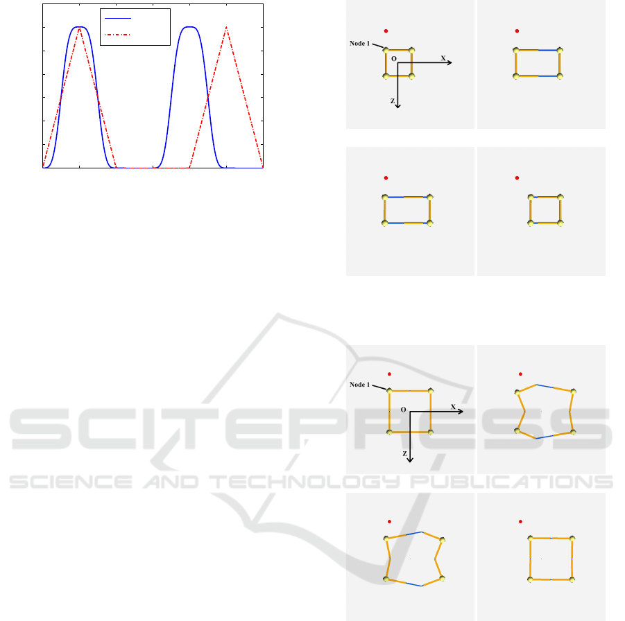
3.1.1 Single Square Module
Figures 5 and 6 show an RPPR and a PRP square
robots moving rightward (i.e., along the +X direc-
tion) using the mentioned moving principle. The con-
ventional RPPR square robot can move faster than
(a) Initial State (b) Step 1
(c) Step 2 (d) Step 3
Figure 5: Conventional square robot obtain a worm-like lo-
comotion within one cycle.
(a) Initial State (b) Step 1
(c) Step 2 (d) Step 3
Figure 6: Proposed square robot obtain a worm-like loco-
motion within one cycle.
the proposed one, since the PRP square robot expe-
riences deformations as shown in Figure 6(b) and (c).
Such a fact can be seen in Figure 7 from which we
can observe that, after actuating the square robots for
32s, the RPPR and PRP square robots move rightward
around 1.0m and 0.7m, respectively.
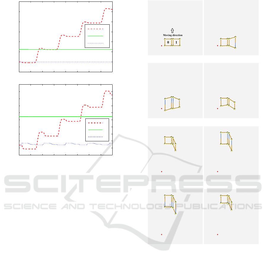
3.1.2 Two Square Modules
In this part, we let MRSs with two square meta-
modules move forward (i.e., along the -Z direction).
A Novel Strut-type Modular Robotic Structure using Rigid Node
265
0 4 8 12 16 20 24 28 32
−0.4
−0.2
0
0.2
0.4
0.6
0.8
1
Time (s)
Node 1 Position (m)
x
y
z
(a) Position profiles of the RPPR square robot
0 4 8 12 16 20 24 28 32
−0.5
−0.4
−0.3
−0.2
−0.1
0
0.1
0.2
0.3
0.4
0.5
Time (s)
Node 1 Position (m)
x
y
z
(b) Position profiles of the PRP square robot
Figure 7: Position profiles synthesized using CPG neural
network based control method.
The corresponding results are shown in Figures 8 and
9. As seen from Figure 8(a)–(d) and Figure 9(a)–(d),
initially, both the two kinds of MRSs can not move
efficiently. After coordinating the phases between the
two square meta-modules, a worm-like locomotion
can be obtained as shown in Figure 8(e)–(h) and Fig-
ure 9(e)–(h). Even though the conventional MRS can
still move slightly faster than the proposed MRS, it
keeps an unstructured shape when achieving a coordi-
nated locomotion. Unlike the conventional MRS, af-
ter some initial deformations, the proposed PRP MSR
can restore and maintain its structured shape. This
is important, as collisions between modules are more
common when moving with an unstructured shape.
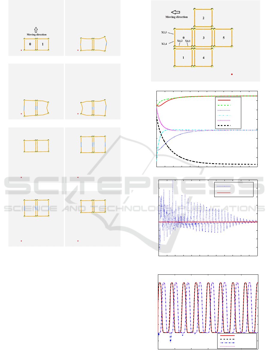
3.1.3 Six Square Modules
For further validation, we established MRSs with six
square meta-modules. The corresponding simulation
results are presented in Figure 10. From the figure, we
can see that the MRSs can obtain a coordinating loco-
motion using the CPG control method. Specifically,
oscillator phases are updated with desired phase off-
sets achieved and actuators’ actual profiles finally co-
incide with their desired counterparts. Note that, dur-
ing the task execution, square meta-module 0’s pris-
matic actuators x
2,3
and x
2,4
are locked. Therefore,
(a) Structure labels (b) Snapshot 1
(c) Snapshot 2 (d) Snapshot 3
(e) Snapshot 4 (f) Snapshot 5
(g) Snapshot 6 (h) Snapshot 7
Figure 8: Locomotion of conventional MSR with two
square meta-modules.
desired values for x
2,3
and x
2,4
are 0. For readability,
we only show the first 60s profiles of actuated actu-
ators x
4,1
and x
4,2
of square meta-module 0. The de-
viation in the x
4,1
profile may result from unexpected
kinematic singularities. In future work, we will de-
vote time to coping with this phenomenon.
3.2 Deformation
A simulation is performed to show the deformation
capability of the proposed strut-type MRSs. Specif-
ically, we construct an MRS with 37 PRP struts as
shown in Figure 11(a). By actuating PRP struts
placed along the top and bottom segments of the
ICINCO 2016 - 13th International Conference on Informatics in Control, Automation and Robotics
266
(a) Structure labels (b) Snapshot 1
(c) Snapshot 2 (d) Snapshot 3
(e) Snapshot 4 (f) Snapshot 5
(g) Snapshot 6 (h) Snapshot 7
Figure 9: Locomotion of proposed MSR with two square
meta-modules.
perimeter using (2)–(5) (with L = 50mm and ϕ
i
(k) =
0rad) and letting other struts be passive, we obtain the
deformation result shown in Figure 11(b). Such a de-
formation can be used for physical display.
4 CONCLUSIONS
This paper presents a novel way of constructing
strut-type MRSs using rigid nodes and robotic struts
equipped with two prismatic and one revolute actua-
tors. For testing such conceptual structures, Webots
is used to construct the physics-based robot models.
(a) Structure labels
0 20 40 60 80 100 120 140 160 180 200 220 240
0
50
100
150
200
250
300
350
400
Time (s)
Phase (deg)
ϕ
0
ϕ
1
ϕ
2
ϕ
3
ϕ
4
ϕ
5
(b) Phase profile
0 20 40 60 80 100 120 140 160 180 200 220 240
−0.08
−0.06
−0.04
−0.02
0
0.02
0.04
0.06
0.08
0.1
Time (s)
Length (mm)
Actual x
2,3
Actual x
2,4
(c) x
2,3
and x
2,4
profiles of square module 0 (with desired values
being 0)
0 10 20 30 40 50 60
−100
−50
0
50
100
150
200
250
300
350
Time (s)
Length (mm)
Actual x
4,2
Desired x
4,2
Actual x
4,1
Desired x
4,1
(d) x
4,2
and x
4,1
profiles of square module 0
Figure 10: Synthesized simulation results of an MSR with
six square meta-modules.
A Novel Strut-type Modular Robotic Structure using Rigid Node
267
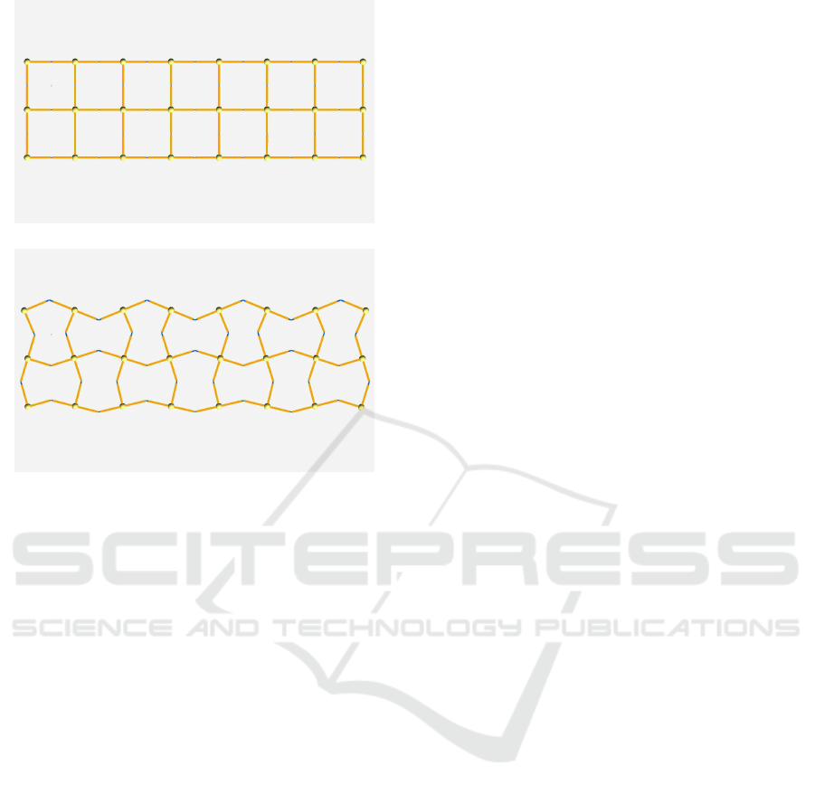
(a) Original shape
(b) Deformation shape
Figure 11: Deformation test of an MRS with 37 PRP struts.
Then, a CPG based control method is implemented
for verifying the performance of the proposed MRSs.
Comparative simulation results demonstrate the effi-
cacy of the control method and the proposed MRSs
as compared with conventional MRSs. Note that, by
using rigid nodes, the difficulty of implementing ideal
compliant nodes has been avoided, thus simplifying
the mechanical design process. Future work will fo-
cus on investigating useful deformation of the MRSs,
designing and building the proposed MRSs, and veri-
fying the control method using physical MRSs.
REFERENCES
Baca, J., Hossain, S. G. M., Dasgupta, P., Nelson, C. A.,
and Dutta, A. (2014). ModRED: Hardware de-
sign and reconfiguration planning for a high dex-
terity modular self-reconfigurable robot for extra-
terrestrial exploration. Robotics and Autonomous Sys-
tems, 62(7):1002–1015.
Cheng, N., Ishigami, G., Hawthorne, S., Chen, H., Hansen,
M., Telleria, M., Playter, R., and Iagnemma, K.
(2010). Design and analysis of a soft mobile
robot composed of multiple thermally activated joints
driven by a single actuator. In Proceedings of the
IEEE International Conference on Robotics and Au-
tomation, pages 5207–5212.
Curtis, S., Brandt, M., Bowers, G., Brown, G., Cheung,
C., Cooperider, C., Desch, M., Desch, N., Dorband,
J., Gregory, K., Lee, K., Lunsford, A., Minetto, F.,
Truszkowski, W., Wesenberg, R., Vranish, J., Abra-
hantes, M., Clark, P., Capon, T., Weaker, M., Watson,
R., Olivier, P., and Rilee, M. L. (2007). Tetrahedral
robotics for space exploration. In Proceedings of the
IEEE Aerospace Conference, pages 1–9.
Hamlin, G. J. and Sanderson, A. C. (1998). TETROBOT:
A Modular Approach to Reconfigurable Parallel
Robotics. Springer, New York.
Kurokawa, H., Yoshida, E., Tomita, K., Kamimura, A., Mu-
rata, S., and Kokaji, S. (2006). Self-reconfigurable M-
TRAN structures and walker generation. Robotics and
Autonomous Systems, 54(2):142–149.
Lyder, A. (2010). Towards Versatile Robots Through Open
Heterogeneous Modular Robots. PhD thesis, Univer-
sity of Southern Denmark.
Østergaard, E. H., Kassow, K., Beck, R., and Lund, H. H.
(2006). Design of the ATRON lattice-based self-
reconfigurable robot. Autonomous Robots, 21(2):165–
183.
Ramchurn, V., Richardson, R. C., and Nutter, P. (2006).
ORTHO-BOT: A modular reconfigurable space robot
concept. In Tokhi, M., Virk, G., and Hossain, M., ed-
itors, Climbing and Walking Robots, pages 659–666.
Springer, Berlin Heidelberg.
Salemi, B., Moll, M., and Shen, W.-M. (2006). SUPER-
BOT: A deployable, multi-functional, and modular
self-reconfigurable robotic system. In Proceedings of
the IEEE/RSJ International Conference on Intelligent
Robots and Systems, pages 3636–3641.
Sato, T., Kano, T., and Ishiguro, A. (2011). On the ap-
plicability of the decentralized control mechanism ex-
tracted from the true slime mold: a robotic case study
with a serpentine robot. Bioinspiration and Biomimet-
ics, 6(2):026006.
Spr¨owitz, A., Moeckel, R., Vespignani, M., Bonardi, S.,
and Ijspeert, A. J. (2014). Roombots: A hardware
perspective on 3D self-reconfiguration and locomo-
tion with a homogeneous modular robot. Robotics and
Autonomous Systems, 62(7):1016–1033.
Yim, M., Shen, W.-M., Salemi, B., Rus, D., Moll,
M., Lipson, H., Klavins, E., and Chirikjian, G. S.
(2007). Modular self-reconfigurable robot systems
[grand challenges of robotics]. IEEE Robotics Au-
tomation Magazine, 14(1):43–52.
Yu, C.-H. (2010). Biologically-Inspired Control for Self-
Adaptive Multiagent Systems. PhD thesis, Harvard
University.
Zagal, J. C., Armstrong, C., and Li, S. (2012). Deformable
octahedron burrowing robot. In Adami, C., Bryson,
D. M., Ofria, C., and Pennock, R. T., editors, Artificial
Life 13, pages 431–438. MIT Press, Cambridge.
Zhang, Y., Yim, M., Eldershaw, C., Duff, D., and Roufas,
K. (2003). Scalable and reconfigurable configurations
and locomotion gaits for chain-type modular recon-
figurable robots. In Proceedings of the IEEE Inter-
national Symposium on Computational Intelligence in
Robotics and Automation, pages 893–899.
ICINCO 2016 - 13th International Conference on Informatics in Control, Automation and Robotics
268
