
Hardware-software Co-simulation of Self-organizing Smart Home
Networks
Who am I and Where Are the Others?
Bruno Kleinert
1
, Franziska Sch
¨
afer
2
, Jupiter Bakakeu
2
, Simone Weiß
1
and Dietmar Fey
1
1
Informatik 3 (Rechnerarchitektur), Universit
¨
at Erlangen-N
¨
urnberg, Martensstr. 3, 91058, Erlangen, Germany
2
Fertigungsautomatisierung und Produktionssystematik, Universit
¨
at Erlangen-N
¨
urnberg,
91058, Erlangen, Egerlandstr. 7-9, Germany
Keywords:
Hardware-software Co-simulation, QEMU, Virtual Distributed Ethernet, SystemC, Self-organization, Home
Automation, Smart Home.
Abstract:
In this paper, we present our solution to simulate home automation networks on a functional level in our re-
search project on self-organizing home automation network nodes. We simulate the nodes with our hardware-
software co-simulator, based on the virtual machine QEMU and the SystemC hardware simulator. The Virtual
Distributed Ethernet suite is used to simulate several hardware-software co-simulators in a network. Further-
more, tools we developed to prepare network node disk images, configure the simulation environment, and
generate Linux device drivers from hardware interface specifications are presented.
1 INTRODUCTION
The demographic change has a huge impact on todays
focus of research and development in various fields of
our everyday life. In combination with the deep pen-
etration of new information and communication tech-
nologies in our society the evolution to personalized
homes that supports its inhabitants in a sensitive and
expedient way becomes more and more attractive. For
such an adaptable and intelligent home, various inter-
acting sensors and actuators are indispensable, result-
ing in a complex network of heterogeneous compo-
nents. The development of such intelligent sensor and
actuator network nodes and the integration of nodes in
existing networks can be a tedious work.
In this paper we present a smart home network
simulation environment, that targets sensor and actua-
tor developers and smart home integrators to simplify
development and integration processes. Common
among most nodes is that they are built from soft-
ware and hardware components and a wired or wire-
less network connection. To simulate a virtual smart
home network, we present our hardware-software
co-simulator (HW-SW co-simulator) and our virtual
simulation environment, based on Virtual Distributed
Ethernet (VDE) (Davoli, 2005).
This paper is organized as follows. Section 2
presents our research project and motivation. Related
work and projects are presented in Section 3. In Sec-
tion 4 we present our hardware-software co-simulator.
Network simulation infrastructure and tools that are
needed for our research project are presented in Sec-
tion 5, while the simulation results are presented in
Section 6. Section 7 concludes this paper. In Section
8 we present future additions to the presented work.
2 MOTIVATION
The vision of smart homes is based on the idea of
a ”digital ecosystem” intended for fulfilling their in-
habitants’ needs and goals, including the aspects self-
organization, scalability and, sustainability (Briscoe
and De Wilde, 2006). This description can be un-
derpinned by observations about ecosystems and their
self-organization in nature. Ants as important players
in natural ecosystems are a good example to observe
self-organization in its perfection. Every ant colony
embodies a decentralized system depending on the
collaboration of its individuals to achieve a common
global goal which is not reachable for a single ant.
The underlying communication system is based on
stimuli and corresponding threshold levels. This role
model can also be transferred to the field of home au-
tomation. Figure 1 shows a collaboration of hetero-
304
Kleinert, B., Schäfer, F., Bakakeu, J., Weiß, S. and Fey, D.
Hardware-software Co-simulation of Self-organizing Smart Home Networks - Who am I and Where Are the Others?.
DOI: 10.5220/0006005703040311
In Proceedings of the 6th International Conference on Simulation and Modeling Methodologies, Technologies and Applications (SIMULTECH 2016), pages 304-311
ISBN: 978-989-758-199-1
Copyright
c
2016 by SCITEPRESS – Science and Technology Publications, Lda. All rights reserved
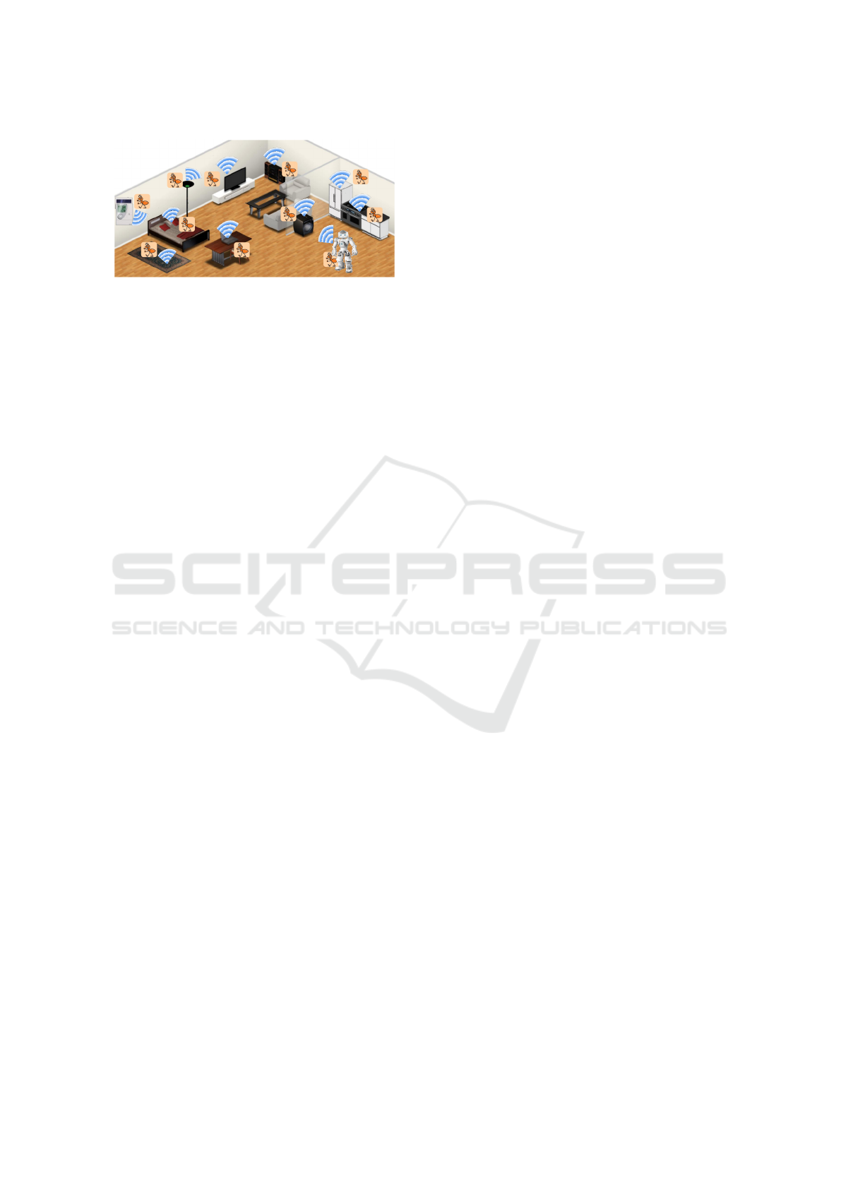
Figure 1: Collaboration of devices with ”ant brains”.
geneous entities with ”ant brains” in a smart home to
comfort the users’ life, e.g. a ”light ant” communi-
cates with a ”brightness” and ”presence sensor ant”
to emit light only if necessary. The fundamental in-
frastructure for this collaboration has to guarantee that
every entity
• has a unique name or identification number
• sees all the other entities
• can interact with every other entity
The realization of this vision requires a stable network
of numerous sensors and actuators. During the plan-
ning phase of a smart home or even in times of ex-
tending an existing system, field tests are not expedi-
ent since end users wish a sophisticated plug and play
solution. In order to ensure functionality and iden-
tify optimal conditions engineers deploy simulations.
They help to gain an insight in complex systems or
a process with a model of reduced complexity with-
out performing time-consuming and expensive exper-
iments. In this paper, with regard to the realization of
a decentralized and self-organizing smart home net-
work, we focus on HW-SW co-simulation and the ver-
ification of virtual networks in a virtual smart home
model.
3 RELATED WORK
Since we built our own HW-SW co-simulator, we an-
alyzed existing ones before. The co-simulator FAU-
machine (Potyra, 2013) emulates an x86 processor
and is able to co-simulate hardware models, described
in VHDL. Though, FAUmachine focuses on fault-
tolerance of operating system (OS) and application
software and is specialized to inject hardware failures
during runtime. Its simulation is fine-grained and pre-
cise, but does not allow the execution of guest code
virtualized on the host processor. The emulation of
the processor results in less performance and interac-
tivity compared to a virtual machine.
As the name of the HW-SW co-simulator QEMU-
SystemC (Yeh et al., 2010) suggests, it is based
on QEMU and SystemC. Further development of
QEMU-SystemC is discontinued. This HW-SW co-
simulator needs to be compiled with a outdated ver-
sion of the GCC compiler suite, otherwise it will crash
unexpectedly during runtime, due to several lines of
invalid C++ code in the glue library that connects
QEMU and the SystemC simulator. Furthermore,
KVM-mode is not allowed to be used for QEMU-
SystemC, which sets a limitation for performance.
The processor-simulator OVP, as presented in
(Schoenwetter et al., 2014), is a precise processor
simulator with SystemC co-simulation capability. It
focuses on precise processor and cache modeling, and
less on complete systems simulation and does not uti-
lize techniques like KVM. As a result, there is no net-
work interface emulation or simulation, which would
be necessary for our smart home simulation. Further-
more, it lacks performance for interactive use.
Due to the shortcomings of the above HW-SW
co-simulators, we implemented our own HW-SW co-
simulator. In (Kleinert et al., 2015) we presented an
earlier stage of our HW-SW co-simulator that was
limited to functional simulations. Although hard-
ware was described in our own XML-based language
instead of directly using SystemC to safe compila-
tion time when hardware changes were necessary, this
language added complexity for hardware developers.
Furthermore, the XML-based language disallowed
the use of typical C/C++ debug techniques, which led
to time consuming development cycles. Also, it de-
manded a doubled effort, when the XML-based lan-
guage needed to be extended, complex SystemC tem-
plates needed to be implemented accordingly.
The lack of simulated time synchronization dis-
allowed testing of time-bound hardware or software
components. For example, it was impossible to use
it for applications that require a hardware and/or soft-
ware watchdog. Also, the Inter Process Communi-
cation (IPC) based on Linux Signals added delays in
data exchange, due to inherent context switches be-
tween the QEMU and SystemC processes and the Op-
erating System (OS).
4 HARDWARE-SOFTWARE
CO-SIMULATION
In this Section we present our HW-SW co-simulator,
based on the virtual machine QEMU and the hardware
simulator SystemC. In the following, we present our
interface to connect both with each other.
Hardware-software Co-simulation of Self-organizing Smart Home Networks - Who am I and Where Are the Others?
305
4.1 Hybrid Simulation Coupling
For our coupling of QEMU and the SystemC simula-
tor, we implement a hybrid interface, i.e., a mixture of
emulation and simulation. QEMU already is a hybrid,
using emulation for peripheral hardware and virtual-
ization of the host processor, when run in KVM-mode
(Kivity et al., 2007).
In (Kleinert et al., 2015) we presented a previous
development stage of our HW-SW co-simulator, that
we further improve to use it for smart home network
simulations. Since it was used to simulate a medical
X-ray controlling computer, we reused our existing
PCI-Express expansion card emulation.
It emulates 1MiB of 32bits registers that are
mapped into the address space that QEMU emulates
for guests. A device driver can then access the regis-
ters after properly initializing the memory mapping.
We implement the registers as an array, which resides
in a shared memory segment (SHM), that other pro-
cesses can map into their own address space. For the
HW-SW co-simulation, the SystemC simulator pro-
cess maps this SHM segment to access the emulated
registers. In the SystemC process, copies of the regis-
ters exist as SystemC registers. The process maps the
SHM segment with the register array into its address
space and keeps the array and the SystemC registers
consistent, i.e., data from the array is converted to
SystemC data types and vice versa on changes. This
builds a hybrid coupling, since the PCI-Express con-
nection in QEMU is emulated, while in the SystemC
process the emulation is connected to a simulation
and kept synchronized.
To signal an event, e.g., a modeled tempera-
ture sensors wants to signal a new measurement
to application software, from the SystemC simula-
tion to QEMU, we use a Linux Remote Procedure
Call (RPC). The RPC emulates an Interrupt Request
(IRQ). Any modeled HW needs to implement the
RPC stub to call the function in our emulated PCI-
Express card in QEMU, that makes the PCI-Express
subsystem in QEMU set the according bit for the re-
ceived IRQ. An Interrupt Service Routine (ISR) can
than handle the IRQ and react accordingly. In Figure
3, the SHM segment, shared between QEMU and the
SystemC simulator, is shown as the RPC to trigger
IRQs in QEMU.
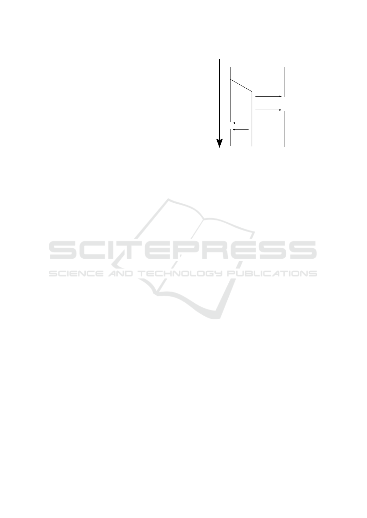
4.2 Synchronization of Simulated Times
The simulated times in QEMU and the SystemC sim-
ulator need to be kept synchronized, to make the co-
simulation result meaningful. While it is desirable
to keep the synchronization on a fine-grained level,
QEMU
HW simulation
set lock
unset lock
set lock
unset lock
simulated time
control thread
Progress
Figure 2: Synchronization thread.
it is limited to the coarse-grained simulator. In our
case, the SystemC simulator can measure time up to a
granularity of femtoseconds, while QEMU measures
time in nanoseconds. As a result, the finest possible
granularity of our HW-SW co-simulator can only be
nanoseconds.
To synchronize simulated times, we start a syn-
chronization thread in QEMU that compares the sim-
ulated times of QEMU and the SystemC simulator.
Should these times deviate from each other, larger
than a user-configurable ε, the synchronization thread
pauses either QEMU or the SystemC simulation. De-
pending on which of them overtook the other one.
Once the slower one has caught up its simulated time,
i.e., the deviation is below ε, the synchronization
thread continues the paused QEMU or SystemC simu-
lator. Figure 2 shows how the synchronization thread
affects QEMU and the SystemC simulator. Figure 3
presents the architecture of our HW-SW co-simulator.
A single instance of our co-simulator represents one
node in a simulated smart home network.
4.3 Device Driver Generation
To achieve a meaningful simulation of a smart home
network, a variety of different nodes should partici-
pate in the simulation, e.g., temperature sensor nodes,
heater actuator nodes, light sensor nodes, light switch
nodes, and so on. From the variety of different nodes
results different sensor and actuator hardware to be
simulated, which means different device driver soft-
ware in each node.
Sensor and actuator nodes typically interact with
their physical surrounding in smart homes. For exam-
ple, the hardware of temperature sensor nodes mea-
sure the surrounding physical temperature, convert
the analogue measurement into a digital value and
pass it to the host processor of the node. Vice versa,
the hardware of an actuator node receive a digital con-
trol value from the host processor of the node and con-
SIMULTECH 2016 - 6th International Conference on Simulation and Modeling Methodologies, Technologies and Applications
306
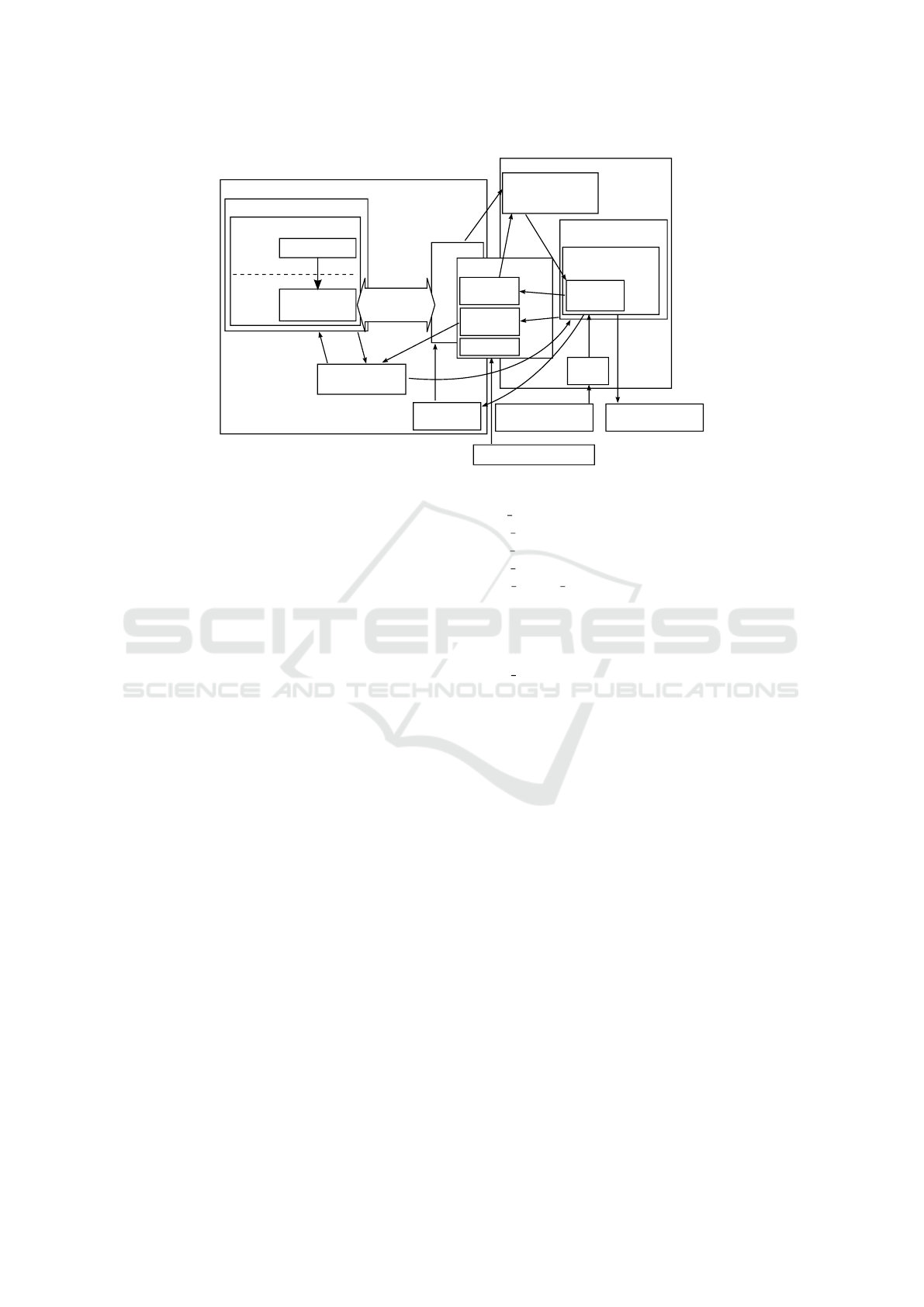
QEMU virtual machine
Linux guest system
I/O card
device driver
Application
User
space
Kernel
space
I/O card
PCI-
Express
Shared memory
Simulated time
control thread
Emulated
registers
Simulated
time
HW simulation
Sensor/actuator
SystemC model
RPC server
for IRQ
SystemC
registers
Stimuli
timer
Stimuli input
configuration file
Signals trace file
Simulation control
loop
QEMU main loop
set/unset
lock
set/ unset
lock
Signal handler/
Update SystemC
registers
Signal on
write access
ε
ε update program
Figure 3: Architecture of our HW-SW co-simulation.
vert it into a physical action, e.g., switching a motor
of a garage door drive on and off. In both cases, an
IRQ can signal a new temperature value, but also a
finished action of the garage door drive to the host
processor. In many cases, sensor and actuator nodes
could fulfill their purpose with hardware that acts as a
converter between the host processor and the physical
world, as a input and output (I/O) device. As a result,
the hardware interface to the host processor should be
similar to some degree among different kinds of sen-
sor or actuator hardware. This, in turn, means that
also the device driver code can be similar among dif-
ferent nodes.
In our approach, we generate device driver code
from the hardware interface specification. In the
context of our emulated PCI-Express interface to-
wards the SystemC simulator, e.g., memory mapping,
PCI Base Address Register addresses, amongst others
have to be covered. On the Linux device driver side,
we identified further required information to generate
a meaningful Linux device driver. Besides the organi-
zational information about the driver author’s name,
mail address, and its textual description, the technical
relevant information is:
Name of the Driver. This distinguishes it from other
device drivers.
ioctl Magic Number. A unique magic number to
distinguish the ioctl calls from other ioctl calls.
PCI-Express Card Name. This distinguishes the
emulated PCI-Express card from other PCI-
Express cards.
Device Node Name. The Linux device file that rep-
resents the device under /dev/.
drv
name : i o t e s t d r v
d r v a u t h o r : J o hn Doe
d r v e m a i l : j o h n . doe@fau . de
d r v d e s c r : I /O c a r d d r i v e r
d r v i o c t l m a g i c : 0 xDE
name : i o c a r d
dev : i o c a r d
v i d : 0 x1234
p i d : 0 x42
b a r s i z e : 1 0 2 4∗1 0 2 4
Figure 4: Specification example.
Vendor ID. The PCI vendor identifier of the emu-
lated card.
Product ID. The PCI product identifier of the emu-
lated card.
Base Address Register (BAR) Size. The size of the
memory region to be mapped in bytes.
Below is an example hardware interface configuration
file, that contains all information needed to derive a
Linux device driver from. The information is placed
into a template device driver code. We implement this
by a shell script that replaces variables with names as
of the left side of the separator ’:’ with its value on
the right side, as presented in Figure 4.
Our script produces C header and source code files
and a header file for the ioctl system call interface that
is common to user and kernel space, e.g., to use the
same ioctl magic number in user and kernel space.
Furthermore a Makefile is generated to compile the
device driver and a configuration rules-file for udev
(Kroah-Hartman, 2003) to make the device driver ac-
cessible for application software as a device file in the
Hardware-software Co-simulation of Self-organizing Smart Home Networks - Who am I and Where Are the Others?
307
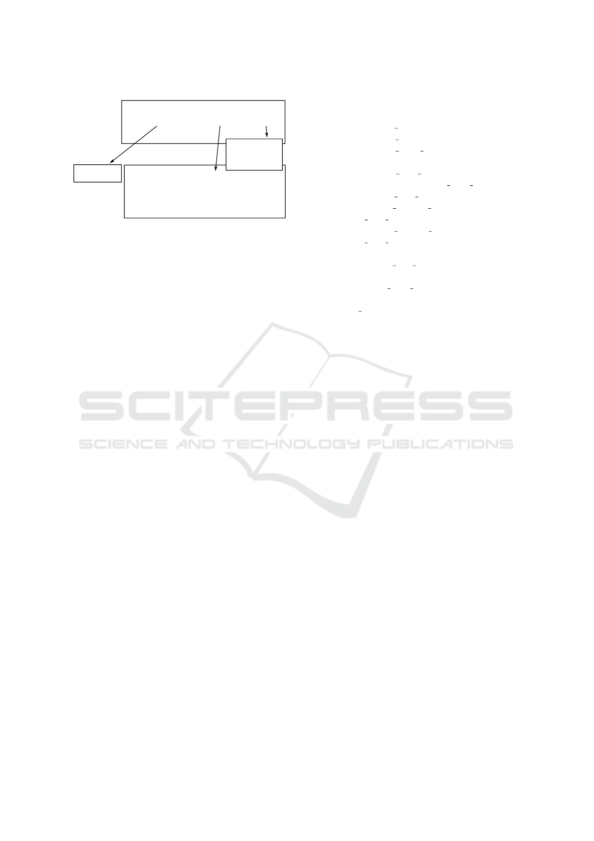
Kernel space (I/O card driver)
User space (command line program)
ioctl (int fd, unsigned in request, void *buf)
/dev/iocard
switch (unsigned int request) {
case 1: ...
case 2: ...
... }
Buffer
64bit address
32bit value
Figure 5: Data exchange via ioctl system call.
directory /dev. The above example specification pro-
duces following output files:
Makefile File with rules for GNU make to compile
the driver.
90-iocard.rules Configuration file for udev to set up
/dev/iocard.
iotestdrv.c The device driver source code.
common.h Common variables and structure for the
ioctl system call to communicate with /dev/iocard.
When the generated driver is loaded into the Linux
kernel, it maps the memory region pointed at by the
BAR field in the PCI-Express configuration space to
a kernel virtual address. This virtual address of 1MiB
size is then configured as an I/O memory region. Af-
ter initialization, udev will create the device file /de-
v/iocard which can be opened by application soft-
ware, i.e., software that interacts with a sensor or ac-
tor. Data exchange via the ioctl system call works
as shown in Figure 5. Reading data from sensors or
sending control data to actuators is done by ioctl sys-
tem calls to the opened device file with an according
prepared ioctl buffer pointer.
Figure 6 shows an excerpt of the generated ioctl
C preprocessor definitions and the stucture common
to user and kernel space for handling ioctl system call
payload. Furthermore, PCI-Express device informa-
tion is presented, that was extracted from the hard-
ware interface specification, necessary to identify the
emulated PCI-Express device interface.
This allows a time saving generation of Linux de-
vice drivers for nodes with hardware interfaces that
differ in BAR size and the number of I/O registers.
If more functionality or different I/O functionality is
necessary, our generation script can be extended and
according variables can be placed in hardware inter-
face specification files.
# i n c l u d e < l i n u x / i o c t l . h>
# d e f i n e IOCARD VID 0 x1234
# d e f i n e IOCARD PID 0 x42
# d e f i n e IOCARD BAR SIZE 10 24 ∗1024
# d e f i n e IOCARD IOC BUFSIZE
s i z e o f ( s t r u c t i o c a r d i o c b u f )
# d e f i n e IOCARD IOC MAGIC 0xDE
# d e f i n e IOCARD IOCW IOW
( IOCARD IOC MAGIC , 1 , i n t )
# d e f i n e IOCARD IOCR IOR
( IOCARD IOC MAGIC , 2 , i n t )
# d e f i n e IOCARD IOC MAXNR 4
s t r u c t i o c a r d i o c b u f {
u n s i g n e d l o n g a d d r ;
u i n t 3 2 t v a l ;
} ;
Figure 6: Generated common header.
5 NETWORK SIMULATION
In this Section, we present our solution to configure
and implement a smart home network simulation. We
use existing Open Source software, but also build our
own tools to mass generate startup scripts containing
respective parameters for QEMU.
5.1 Shared Memory Separation
In order to simulate a network of smart home nodes,
it must be possible to run several of our HW-SW
co-simulators at once. Though it would be possible
to place each instance on a different computer, this
would waste energy and computation power, since
nowadays desktop computers are equipped with mul-
ticore processors that deliver enough computation
power to execute more than a single HW-SW co-
simulation.
As described in (Kleinert et al., 2015), QEMU and
the SystemC simulator are executed as separate Linux
processes, they need to be coupled to each other to ex-
change simulation data. This coupling was achieved
by exchanging each others process identifier (PID)
to send signals to the other simulation partner when
new data is available. In this work we present our
improvements in Section 4 by using SHM. In Linux,
SHM segments are identified by a system wide unique
key. Each process, which wants to map a SHM seg-
ment, needs to know and use the same key, as that
SIMULTECH 2016 - 6th International Conference on Simulation and Modeling Methodologies, Technologies and Applications
308

SHM segment was created with. That means, to
execute several HW-SW co-simulators, each QEMU
and SystemC simulator pair needs to use a different
key for their private SHM segment, otherwise all co-
simulators would work on a single SHM segment,
which would lead to an undefined result.
To have each co-simulation use its own private
SHM segment, the key to identify it, is supplied as
an environment variable. It is read at creation time
of the SHM segment in QEMU and again in the Sys-
temC simulator when it maps the SHM segment into
its own address space. The control over correct SHM
mapping among all co-simulators on the same host
computer is handed over to the supervisor of the smart
home network simulation.
5.2 Ethernet Simulation
In this work, we assume the nodes exchange data in
a smart home Ethernet network. We assume it is
transparent to the software if it exchanges data via
wired or wireless Ethernet. We use the Virtual Dis-
tributed Ethernet (Davoli, 2005) framework to sim-
ulate an Ethernet network, which works by start-
ing the vde switch program. It creates a socket in
/tmp/vde.ctl to which each QEMU can connect to
communicate over the simulated VDE network. No
changes were necessary to make QEMU utilize VDE,
since that support is already implemented. QEMU
needs to be started with the command line parameter
-net vde,sock=/tmp/vde.ctl amongst other.
The above method allows to simulate a limited
number of nodes, as the simulated nodes consume
processor time, until the host processor is used to ca-
pacity. vde switch allows to overcome this limita-
tion by connecting them transparently through Linux
tunnel virtual Ethernet devices with each other. A
smart home network of 10 hosts, each running 10
HW-SW co-simulators as smart home network nodes
can simulate a network of 100 nodes by tunneling the
vde switch connections.
5.3 Node Software Preparation
Regarding the example mentioned in Section 5.2 of
simulating 100 nodes, a preparation for such a simu-
lation quantity by hand would be a tedious task. To
avoid such a torture, we implemented the tool gen-
flock to generate startup scripts containing calls to
start each QEMU and prepare its disk image from a
template image and application payload per node.
For genflock, we prepared a Debian GNU/Linux
1
template disk image. Genflock expects as parame-
1
https://www.debian.org/
ters a template disk image file, the number of nodes
to generate, the size of the Random Access Mem-
ory (RAM) for each node and a hostname prefix for
each node, which will be enumerated as a suffix. If
the hostname is set to sheep, the nodes will be given
names beginning with sheep-01, sheep-02 and so on.
To prepare data, or compile and install soft-
ware, a pre-installation and post-installation hook-
mechanism can execute arbitrary tasks. If a file nn pre
exists, each line in it will be executed as a shell com-
mand. This should be used to compile software to be
installed in the image. Arbitrary directories and files
can be installed into a specific disk image, when a
directory nn payload exists. The content of this di-
rectory will be installed unmodified in the disk im-
age. If a file nn post exists, each line in it will be exe-
cuted after nn payload was copied into the disk image
filesystem tree. This allows adjustments, e.g. correct-
ing file permissions and flags. We use the program
guestmount from the libguestfs project(Jones, 2010)
to mount the first partition of our template disk image
via File System in User Space (FUSE) (Rajgarhia and
Gehani, 2010).
6 RESULTS
As we presented our implementation of our frame-
work for a smart home network simulation, our goal
is a successful generation of a test environment of 10
nodes for one host machine (See Section 8 regarding
inter-host simulation). We implement a sensor node
hardware description in SystemC, switches every 5
seconds between two fixed light intensities and sends
them to the host processor. As actuator hardware, we
implement a light controller, that prints out the cur-
rently set light intensity to the text console. To proof
working network functionality, each node uses avahi
2
to discover the remaining 9 nodes in the simulated
network. We use the Linux utility lspci to discover
the hybrid emulated/simulated hardware sensor and
actuator.
It takes 38 seconds to start 10 nodes on a Intel
Core i7 CPU, each node equipped with 256MiB of
RAM, while the disk image format is qcow2 and the
underlying file system is a Btrfs of Linux 3.16 on a
7200rpm hard disk. Figure 7 shows the output of the
service and network discovery tool avahi-browse, dis-
playing the successful discovery in QEMU of all 10
nodes in the simulated network.
Figure 8 shows the driver initialization debug out-
put of our test driver for the emulated registers and the
2
http://www.avahi.org/
Hardware-software Co-simulation of Self-organizing Smart Home Networks - Who am I and Where Are the Others?
309
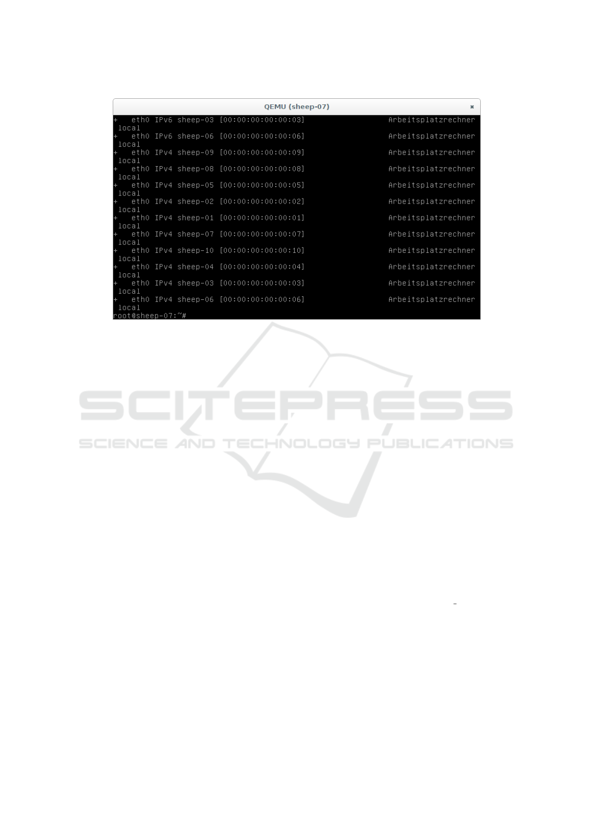
Figure 7: Node discovery.
working udev configuration file, as /dev/iocard was
created to access the driver and the registers. Addi-
tionally, the output of the lspci utility shows the PCI-
Express configuration of our device with Vendor ID
0x1234 and Product ID 0x0042. Also the assigned
IRQ 11 is displayed.
7 CONCLUSION
In this paper we presented our research project of au-
tonomous self-organizing home automation network
nodes, in which the presented simulation environ-
ment and tool-chain to simulate Ethernet networks
is used. We presented our hardware-software co-
simulator, that is based on the virtual machine QEMU
and the SystemC hardware simulator. Through the
Virtual Distributed Ethernet suite, we connected 10
instances of our co-simulator on a single host com-
puter to an Ethernet network. By a network ser-
vice discovery Linux utility, we assured that all co-
simulator instances have network access to each other.
We presented our tool-chain to generate configu-
rations to start each co-simulator instance with proper
parameters. To avoid time consuming manual prepa-
ration of software for our co-simulator, we presented
our tool-chain to generate Linux device drivers from
hardware interface specifications by using template
device driver code. Additionally to driver code,
also Linux infrastructure configuration files are gen-
erated. Another tool is presented, to mass generate
customized disk images for co-simulator instances,
that saves developers from time consuming manual
preparation of different application software per in-
stance. All generated device drivers and files can be
used by our disk preparation tool, to prepare the op-
erating system per co-simulator instance for different
simulated sensor or actuator hardware.
The presented work speeds up configuring, build-
ing, and starting a simulation environment. To sim-
ulate an Ethernet network, we used the Virtual Dis-
tributed Ethernet software suite. In our smart home
network simulation, the coupling of a virtual machine
and a hardware simulator allows a hardware-software
co-simulation of sensors and actuators, while appli-
cation software can exchange data via the simulated
network.
8 FUTURE WORK
Since we reused the emulated PCI-Express I/O card
as presented in (Kleinert et al., 2015), this limits the
usable platform in QEMU to the x86 64 boards, emu-
lated by QEMU. Though Intel wants to enter the low-
power platform market with x86 SoCs, it makes sense
to port our template driver from the PCI-Express bus
to ARM and MIPS platform buses, since these ar-
chitectures are established in the low-power platform
market that also covers existing home automation
equipment.
A shortcoming in our template driver (See Sec-
tion 4.3) is the limitation to ioctl system call support.
Since the I/O register are memory mapped, support
SIMULTECH 2016 - 6th International Conference on Simulation and Modeling Methodologies, Technologies and Applications
310
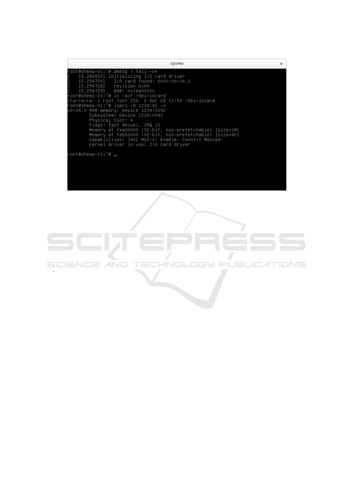
Figure 8: Emulated PCI-Express card.
for the mmap system call should be added, to allow
application software to map the memory region, cov-
ering the emulated I/O registers, into their process
address space to reduce the large number of context
switches introduced by ioctl system calls.
In Section 5.3 we presented our tool that, amongst
others, generates scripts to start the HW-SW co-
simulators. In the current state, it is not aware of the
tunneling capability via Linux TUN/TAP devices of
vde switch, to connect virtual switches across several
simulation hosts. Support should be added to set up
the tunnels and assign co-simulators to host machines.
ACKNOWLEDGEMENT
This work was carried out in the E|Home Center
project decentralized control in private residential by
smart sensors and OPC UA, based on paradigms of
Industry 4.0. We would like to thank the Bavarian
State Ministry of Education, Science and the Arts for
funding this project.
REFERENCES
Briscoe, G. and De Wilde, P. (2006). Digital ecosystems:
evolving service-orientated architectures. In Proceed-
ings of the 1st international conference on Bio in-
spired models of network, information and computing
systems, page 17.
Davoli, R. (2005). Vde: Virtual distributed ethernet. In
Testbeds and Research Infrastructures for the Devel-
opment of Networks and Communities, 2005. Trident-
com 2005. First International Conference on, pages
213–220.
Jones, R. W. (2010). Visi
´
on interior: manipulaci
´
on
de im
´
agenes de discos de m
´
aquinas virtuales con
libguestfs. Linux magazine, (66):23–26.
Kivity, A., Kamay, Y., Laor, D., Lublin, U., and Liguori, A.
(2007). kvm: the Linux virtual machine monitor. In
Proceedings of the Linux Symposium, volume 1, pages
225–230.
Kleinert, B., Rahimi, G. R., Reichenbach, M., and Fey, D.
(2015). Hardware-software co-simulation for medi-
cal x-ray control units. In Proceedings of the 8th In-
ternational Conference on Simulation Tools and Tech-
niques, pages 305–307.
Kroah-Hartman, G. (2003). udev–A Userspace Implemen-
tation of devfs. In Proc. Linux Symposium, pages 263–
271.
Potyra, S. (2013). Transparente und hochperfor-
mante VHDL-Cosimulation im Kontext der virtuellen
Maschine FAUmachine. PhD thesis, Univer-
sit
¨
atsbibliothek der Universit
¨
at Erlangen-N
¨
urnberg.
Rajgarhia, A. and Gehani, A. (2010). Performance and ex-
tension of user space file systems. In Proceedings
of the 2010 ACM Symposium on Applied Computing,
pages 206–213.
Schoenwetter, D., Schneider, M., and Fey, D. (2014). White
Light Interferometry on Embedded Hardware. Jour-
nal of Computer Engineering and Informatics Jan,
2(1):138–147.
Yeh, T.-C., Tseng, G.-F., and Chiang, M.-C. (2010). A
fast cycle-accurate instruction set simulator based on
QEMU and SystemC for SoC development. In MELE-
CON 2010 - 2010 15th IEEE Mediterranean Elec-
trotechnical Conference, pages 1033–1038.
Hardware-software Co-simulation of Self-organizing Smart Home Networks - Who am I and Where Are the Others?
311
