
Model Predictive Control for Y-source Boost DC-DC Converter
Jean Thomas
Process Control Dep., FIE, Beni-Suef University, Ben-Suef, Egypt
Keywords: Boost DC-DC Converter, Model Predictive Control, Impedance Network.
Abstract: Recently a new topology called Y-source impedance network has been proposed to enhance the performance
of boost dc-dc converters. The Y-source boost dc-dc converter has shown its ability to offer high gain voltage
with small duty ratio. This paper presents an algorithm based on Model Predictive Control (MPC) to control
the Y-source boost DC-DC converter. An analytical MPC algorithm reducing the computation time is
proposed. Using this technique a fast response and steady state output can be achieved. Besides, the proposed
controller controls directly the switch position, so Pulse-Width Modulation (PWM) is not required in this
technique. The proposed algorithm offer optimal solution in reasonable time and it is not considered as a
computation burden, thus real-time implementation is possible; overcoming the inherent drawback of classical
MPC controller. Simulation results, demonstrating the controller capabilities to produce the required high
gain voltage, are presented.
1 INTRODUCTION
Recently many of researchers focused on the
development of boost dc-dc converter with high gain
voltage. Several impedance networks have been
proposed to enhance the power conversion with high
voltage gain. Introducing coupled magnetic has been
lately proposed to improve the impedance network
while using a shorter duty ratio. In this direction
several techniques has been presented in literature
like the T-Source (Strzelecki et al., 2009), Z-source
(Qian et al., 2011), TZ-source (Nguyen et al., 2013),
Γ-source (Loh et al., 2013) and Y-source (Siwakoti et
al., 2014). The obtained gain of Y-source is presently
not matched by other networks operated at the same
duty ratio; a mathematical derivation and
experimental results have proven this capability
(Siwakoti et al., 2014). The Y-source has been
considered as generic network, from which the other
networks can be derived (Siwakoti et al., 2015).
On the other hand, Model Predictive Control
(MPC) appears to be an efficient strategy to control
many applications in numerous industries. It can
efficiently control a great variety of processes,
including systems with long delay times, non-
minimum phase systems, unstable systems,
multivariable systems, constrained systems and
hybrid systems (Camacho and Bordons, 1999),
(Maciejowski, 2002), (Thomas et al., 2004), as well
as systems with discrete inputs only (Thomas, 2012).
MPC has become an accepted standard for
constrained multivariable systems (Mayne et al.,
2000).
Many applications of MPC controller in power
electronics area have been presented in litrature, for
example in (Wang, 2012) and (Vazquez et al., 2014),
including controls of traditional boost converters
(Beccuti et al., 2007) and (Murali et al., 2010). The
main contribution of this paper is to develop a MPC
algorithm to control the output voltage of the Y-
source boost dc-dc converter. The proposed controller
based on analytical computation of the cost function
for both of On and Off states of the single switch. The
proposed MPC algorithm controls directly the switch
position to obtain the required gain voltage.
The rest of the paper is organized as following;
section 2 briefly presents the Y-source boost dc-dc
converter, while the concepts of MPC has been
presented in section 3. Section 4 presents the
proposed MPC algorithm for Y-source dc-dc
converter. Results are demonstrated in section 5.
Finally conclusion and some remarks are given in
section 6.
Thomas, J.
Model Predictive Control for Y-source Boost DC-DC Converter.
DOI: 10.5220/0006006302750280
In Proceedings of the 13th International Conference on Informatics in Control, Automation and Robotics (ICINCO 2016) - Volume 1, pages 275-280
ISBN: 978-989-758-198-4
Copyright
c
2016 by SCITEPRESS – Science and Technology Publications, Lda. All rights reserved
275
2 THE METHEMATICAL MODEL
OF Y-SOURCE BOOST DC-DC
CONVERTER
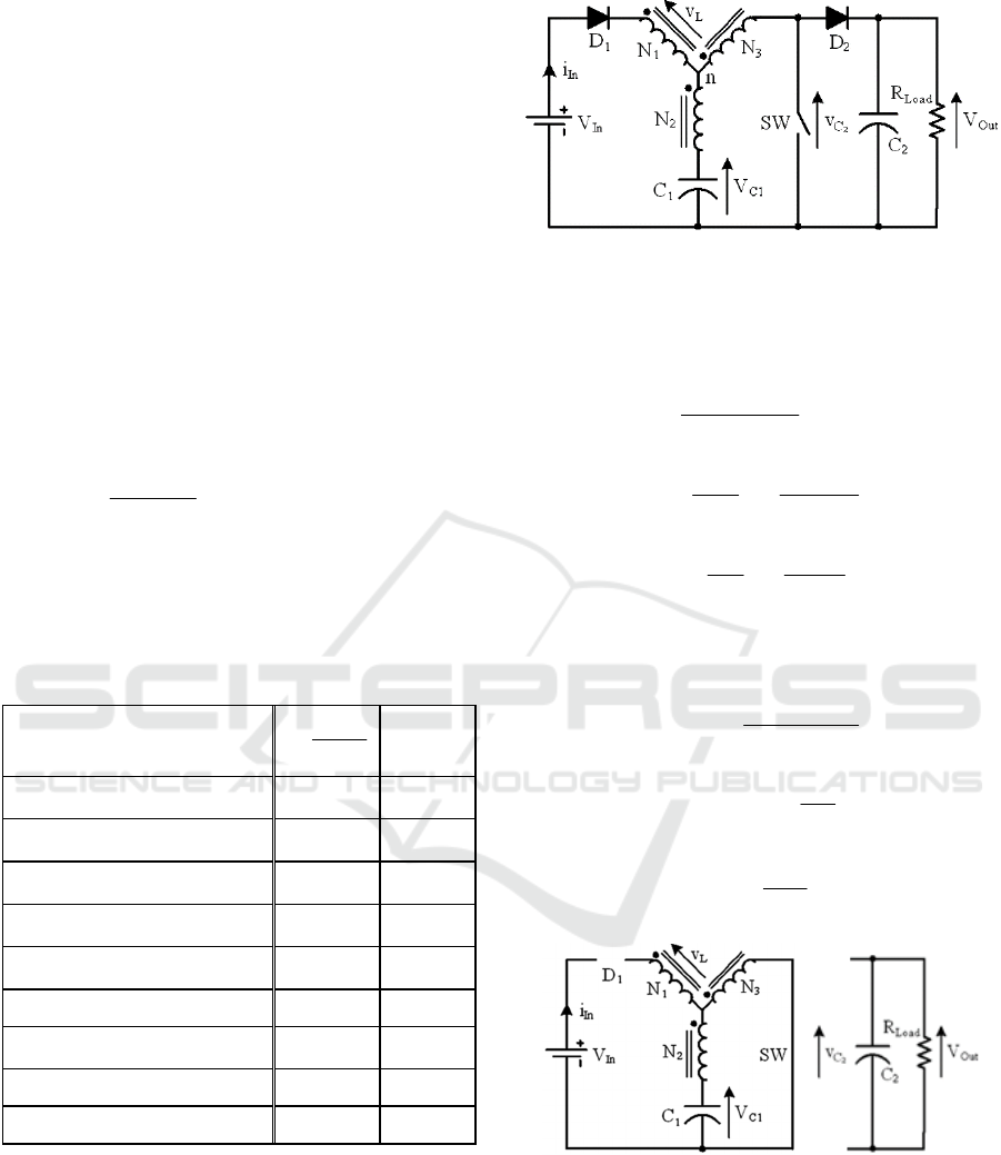
Recently, the Y-shaped impedance network that can
offer a high-voltage gain converter while using a
small duty ration is proposed (Siwakoti et al., 2014).
It uses a tightly coupled transformer with three
windings. An application of Y-shaped impedance
network with a single switch dc-dc converter (Figure
1) has shown its ability to offer more degrees of
freedom for varying its gain. The voltage gain of Y-
source boost dc-dc converter is given by (1); the
mathematical derivation is given in (Siwakoti et al.,
2014):
]1/[
stinout
KdVV
(1)
where
23
13
NN
NN
K
,
321
,, NNN
are the winding
turns of the three windings and
st
d
is the duty ratio.
The gain of (1) and its related turns ratio are
summarized in Table 1 (Siwakoti et al., 2014).
Table 1: Gain of Y-source boost dc-dc converter with
different winding factor K and Turns Ratio (N
1
:N
2
:N
3
).
N1:N2:N3
23
13
NN
NN
K
Gain
(1:1:3),(2:1:4),(1:2:5),(3:1:5),(4:1:6)
, (1:3:7)
2 (1-2d
st
)
-1
(1:1:2),(3:1:3),(2:2:4),(1:3:5),
(4:2:5)
3 (1-3d
st
)
-1
(2:1:2),(1:2:3),(5:1:3),(4:2:4),
(8:1:4)
4 (1-4d
st
)
-1
(3:1:2),(2:2:3),(1:3:4),(7:1:3),
(6:2:4)
5 (1-5d
st
)
-1
(4:1:2),(3:2:3),(2:3:4),(1:4:5),
(9:1:3)
6 (1-6d
st
)
-1
(5:1:2),(4:2:3),(3:3:4),(2:4:5) 7 (1-7d
st
)
-1
(6:1:2),(5:2:3),(4:3:4),(3:4:5),
(2:5:6)
8 (1-8d
st
)
-1
(7:1:2),(6:2:3),(5:3:4),(4:4:5) 9 (1-9d
st
)
-1
(8:1:2),(7:2:3),(6:3:4) 10 (1-10d
st
)
-1
In the following the mathematical models of the
Y-source converter for both of the ON and OFF
positions of the switch SW are delivered.
When SW is turned ON, D
1
and D
2
are reverse-
biased (i.e. turn off), causing C
1
to charge the
magnetizing inductance of the transformer. At the
same time, C
2
discharges to power the load. the
equivalent circuit in this case is shown in Figure 2,
and the circuit analysis is as follows:
Figure 1: Single-switch Y-source dc–dc boost converter.
0//
13121
nVnVV
LLc
(2)
where
2112
/ NNn
and
3113
/ NNn
, then:
)(
)(
)(
1
1312
1312
tV
nnL
nn
ti
cL
(3)
1
12
1
1
1
)(
)(
C
tin
C
i
tV
L
C
C
(4)
o
co
C
rC
tV
C
i
tV
2
2
2
2
)(
)(
(5)
Using the Euler discretization with a sampling time
s
T
:
)(
)(
)()1(
1
1312
1312
kV
nnL
nn
Tkiki
csLL
(6)
)()()1(
1
12
11
ki
C
n
TkVkV
LsCC
(7)
)(
1
1)1(
2
2
2
kV
rC
TkV
C
o
sC
(8)
Figure 2: The equivalent circuit during SW ON.
When the SW is turned OFF, D1 and D2 are
conducting, causing V
in
to recharge C1. Energy from
V
in
and the transformer will also flow to the load. The
equivalent circuit is shown in Figure 3, and the circuit
analysis is as follows:
0/
213
cLLin
VnVVV
(9)
ICINCO 2016 - 13th International Conference on Informatics in Control, Automation and Robotics
276
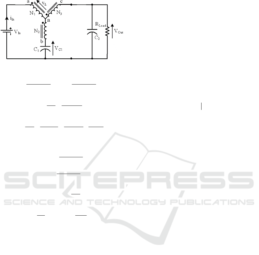
Figure 3: The equivalent circuit during SW OFF.
incL
V
nL
n
tV
nL
n
ti
)1(
)(
)1(
)(
13
13
2
13
13
(10)
1
12
1
1
1
)(
)(
C
tin
C
i
tV
L
C
C
(11)
o
cLoLC
C
rC
tV
C
tin
C
ii
C
i
tV
2
2
2
13
2
3
2
2
2
)()(
)(
(12)
Using the Euler discretization:
ins
csLL
V
nL
n
T
kV
nL
n
Tkiki
)1(
)(
)1(
)()1(
13
13
2
13
13
(13)
)()()1(
1
12
11
ki
C
n
TkVkV
LsCC
(14)
)(
1
1)()1(
2
22
13
2
kV
rC
Tki
C
n
TkV
C
o
sLsC
(15)
These developed equations will be used by the MPC
controller to predicte the future outputs of the Y-
source boost dc-dc converter in both ON and OFF
states; (6)-(8) and (13)-(15) respectively.
3 MODEL PREDICTIVE
CONTROL
Predictive control was first developed at the end of
1970s, and was published by Richalet et al., (1978).
In the 1980s, many methods based on the same
concepts are developed. Those types of controls are
now grouped under the name Model Predictive
Control (MPC) (Camacho and Bordons, 1999). MPC
has proved to efficiently control a wide range of
applications in various industries.
The main idea of predictive control is to use a
model of the plant to predict future outputs of the
system. Based on this prediction, at each sampling
period, a sequence of future control values is
developed through an on-line optimization process,
which maximizes the tracking performance while
satisfying constraints. Only the first value of this
optimal sequence is applied to the plant. The whole
procedure is repeated again at the next sampling
period according to the ‘receding’ horizon strategy
(Maciejowski, 2002). The objective is to lessen the
future output error to zero with minimum input effort.
The cost function to be minimized is generally a
weighted sum of square predicted errors and square
future control values, e.g., in Generalized Predictive
Control (Clarke et al., 1987):
u
N
j
N
j
u
jku
jkwkjkyNNJ
1
2
1
2
)1(
)()(
ˆ
),(
(16)
where
uy,
ˆ
are the predicted output and the control
signal respectively.
u
NN,
are the prediction
horizons and the control horizon, respectively.
,
are weighting factors. The control horizon permits a
decrease in the number of the calculated future
control assuming
0)(
jku
for
u
Nj
.
)( jkw
is the reference trajectory.
Constraints over the control signal, the outputs
and the control signal changing, can be added to the
cost function:
maxmin
maxmin
maxmin
)(
)(
)(
ykyy
ukuu
ukuu
(17)
The solution of (16) gives the optimal sequence of the
control signal over the horizon
u
N
while respecting
the given constraints of (17).
4 MPC FOR Y-SOURCE DC-DC
CONVERTER
As the switch of the inverter has only two different
positions; ON and OFF, an analytical computation of
the tracking performance, for the two possible
position combinations can be performed. Then the
position of the switch, which is the manipulated
variable, which maximizes the tracking performance
is selected.
Model Predictive Control for Y-source Boost DC-DC Converter
277

The objective function that captures the tracking
performance includes the error between the actual
output voltage
out
V
and the reference trajectory of the
output voltage. To minimize the inverter switching
frequency a penalty term on the control variations is
included in the objective function. The considered
objective function is:
1
0
2
1
2
)1()(
)()(
ˆ
u
N
j
j
N
j
rout
jkujkuP
jkVkjkVQJ
(18)
where
out
V
ˆ
is the predicted future output voltage,
r
V
is the output voltage reference,
u
is the ON/OFF
control signal, and where
Q
and
j
P
the weighting
matrixes are positive constants. The second term
penalizes the switch position variation. The objective
function (18) is minimized subject to constraints that
describe the discretized dynamics in (6)-(8), and (13)-
(15).
The constants
j
P should impose more penalties
over the first time-steps than the later steps, to force
the transition of the switch to occur as late as possible
(Papafotiou et al., 2007). This is accomplished by the
following constraints:
110
u
N
PPP
(19)
The objective function (18) is evaluated
u
N
s 2
times at each time step, and the first control signal in
the sequence
))1(),...,((
u
opt
Nkukuu
corresponding to the minimum objective function
value is then selected and applied to the inverter
switch.
Increasing the prediction horizon
N
will lead to
more accurate choice of control signals. However,
increasing the prediction horizon will increase the
computational time. To account for that, we propose
to use different discrete time models with different
sampling times as described in (Thomas and
Hansson, 2013). For the first sampling steps we use a
model with the true sampling time, and then for later
sampling steps we use another model with longer
sampling time. This will increase the prediction
interval with less number of prediction steps as
compared to when using the same sampling time for
all predictions.
To avoid examining all possible input switching
over the control horizon
N
the following
incremental algorithm is proposed to compute the
optimal control signal sequence. Here
i
u
is a
candidate optimal control signal sequence that is an
element in
uuu
...
.
Algorithm 1.
1- Initializing with
0)(, kJJ
i
opt
2- For
si
i
,,2,1, u
where ݏ is the total
number of possible input combinations over
horizon ܰ
3- For
Nj :1
4- Compute
)( jkJ
i
the cost function
according to the control combination
i
u
for horizon j as following:
1,)1()( jkjkfjkJjkJ
iii
ux
where
1, jkjkf
i
ux
is the cost
at instant
jk
due to the control signal
1 jk
i
u
.
5- If
opt
i
JjkJ )(
Break and go to step 2
end
end
6- At
Nj
If
)()( NkJJJNkJ
i
optopt
i
end
End
7-
opt
opt
JJ
*
the optimal solution
The incremental cost (in step 4 of Algorithm 1) is
the predicted cost at time step
jk
due to the control
signal
1 jku
i
, and it is given by
2
)1()(
)()(
ˆ
1,|
ˆ
2
jkujku
j
P
jkwkjk
out
VQjk
i
ukjkvf
Algorithm 1 stops the cost function calculations for
the control sequence
i
u
prematurely if the cost
function at prediction step j , where
Nj 1
, is
higher than the current upper bound
opt
J
. This saves
computational time. The algorithm is similar to one
of the pruning rules in the Branch and Bound (BB)
algorithm for solving integer programs (Fletcher and
Leyffer, 1995).
The proposed controller is faster than other
standard techniques for solving integer programming
ICINCO 2016 - 13th International Conference on Informatics in Control, Automation and Robotics
278
problems like for example BB, as the analytical
computation of the objective function when the
number of optimization variables is small, which is
the case in the considered application, is much faster
than solving a QP optimization problem. Moreover,
the relaxed problem for the suggested MPC algorithm
would not be a quadratic program, since we have
introduced a penalty term on the number of switches
so it could be expensive to solve with classical
optimization technique.
The advantages of the proposed technique besides
its simple design and implementation are that there is
no complicated on-line optimization to be performed.
Moreover there is no need to reformulate the system
in the hybrid system framework, as done in (Beccuti
et al., 2007).
The developed technique significantly reduces the
computational time. Moreover, one extra dimension
of freedom through the choice of the weights
j
P
has
been added, which enables a trade-off between the
average switching frequency and the voltage tracking
performance. Note that reducing the ripple can only
be achieved by increasing the switching frequency
and vice versa.
4.1 Constraints
Output signals and system states can be subject to
constraints. This constraints could, for example,
relate to safety or physical constraints. This
constraints can be included in the proposed controller.
by adding the following line to Algorithm 1:
)()()(
maxmax
jkJyxyxif
i
(20)
Thus any control combination which will lead to
violation of the output or state constraints will be
avoided.
5 RESULTS
The proposed control strategy is applied to the Y-
source boost dc-dc converter shown in Figure 1,
whose parameters are given in Table 2. After
successive tuning iterations, the parameters of the
MPC controller that give a good response are: control
horizon
8 NN
u
, prediction interval
s
T
20
.
The concept of multiple discrete models, as
mentioned previously, is used to reduce the number
of prediction steps; a model with sampling time
s
T
is
used for the first four steps, and then a model with
sampling time equal
s
T4
is used for the next 4 steps,
i.e. the prediction interval of in total
s
T20
is covered
with 8 prediction steps. The weights in the objective
function has been chosen as
100
j
P
, and
10000
Q
. A sampling time T
s
of 10µs is used.
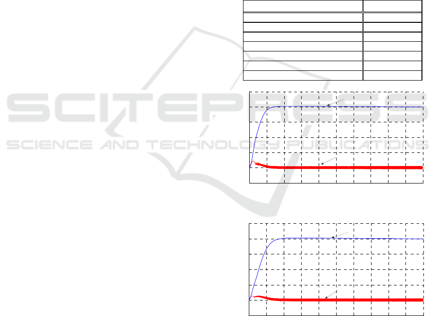
Computer simulations have been carried out in
order to validate the proposed scheme. The Y-source
boost dc-dc converter is assumed to start at t=0 with
zero initial condition (i
l
=0; V
c1
=0; V
c2
=0 and V
out
=0;
start-up) and it is required to support the load with a
voltage V
out
=200V, i.e. a gain of 4 is required. Figure
4 shows the output voltage with the proposed MPC
controller, and also the inductance current i
l
. It is
obvious that the proposed MPC algorithm succeeded
in providing the required output voltage.
Table 2: Parameters of the Y-source boost dc-dc converter.
Parameter/Description Value
Input Voltage V
in
50V
Output Voltage V
out
200V
Capacitance C
1
& C
2
470µF
Turns Ratio: N
1
:N
2
:N
3
80:16:48=5:1:3
Winding Factor K 4
Inductance L 1mH
Load Resistance r
o
1KΩ
Figure 4: Output Voltage and Inductance current.
Figure 5: Output Voltage and Inductance current V
in
=30V.
Figure 5 shows the case when the input voltage
source V
in
drops to 30V, the controller succeeded in
tracking the reference of output voltage, however it
takes relatively more time to reach the steady state
value, and the mode of ON was more selected by the
0 1000 2000 3000 4000 5000 6000 7000 8000 9000 10000
-50
0
50
100
150
200
250
Sampling Instants
Output Voltage and Inductance Current
Ind uctance Current i
l
Output Voltage V
out
0 1000 2000 3000 4000 5000 6000 7000 8000 9000 10000
-50
0
50
100
150
200
250
Sampling Instants
Output Voltage and Inductance Current
Output V oltag e V
out
Inductance Current i
l
Model Predictive Control for Y-source Boost DC-DC Converter
279

controller to compensate the voltage source drop.
Applying Algorithm 1 to reduce the number of
cost function evaluation, for
8N
,
the average
number of cost function evaluation was 95 times
instead of
8
2
= 258 times, with reduction ratio of
62.9%. The technique presented here does not require
average model of the switched system, moreover the
proposed controller controls directly the switch, and
hence the PWM inverter is not needed. This technique
can be extended and applied to other types of
converters possibly with multiple switches.
6 CONCLUSIONS
In this paper an algorithm based on model predictive
control is used to control the Y-source boost dc-dc
converter. The proposed algorithm computes
analytically the cost function, a reduction technique
to avoid evaluating the all possible cost function over
the prediction horizon is used. The developed
controller controls directly the inverter switches to
track the output voltage trajectory. With this
technique there is no need to use a PWM inverter, and
moreover, it reduces significantly the computational
time, which is an inherent drawback of classical MPC
controllers. Thus real time implementation is
possible. It is simple to construct, to implement and
to tune.
Future work will include experimental works to
validate this technique in practice. Finally, the same
technique will be examined for other topologies with
other types of converters possibly with multiple
switches.
REFERENCES
Beccuti A.G., G. Papafotiou, M. Morari, S. Almer, H.
Fujioka, U. Jonsson, C.-Y. Kao, A. Wernrud, A.
Rantzer, M. Baja, H. Cormerais and J. Buisson. Hybrid
Control Techniques for Switched-Mode DC-DC
Converters. Part II: The Step-Up Topology. Proc.
American Control Conference, New York City, USA,
July 11-13, 2007.
Beccuti A.G., G. Papafotiou, Roberto Frasca, M. Morari.
Explicit Hybrid Model Predictive Control of the dc-dc
Boost Converter. IEEE PESC, Power Electronics
Specialists Conf., Orlando, Florida, USA, 2007.
Camacho, E. F. et C. Bordons, 1999. Model predictive
control. Springer-Verlag, London.
Clarke, D.W., C. Mohtadi et P. S. Tuffs, 1987. Generalized
predictive control – Part I. and II. Automatica, Vol.23
(2), pp. 137-160.
Fletcher R. and S. Leyffer. Numerical experience with
lower bounds for MIQP branch and bound. Technical
report, Dept. of Mathematics, University of Dundee,
Scotland, 1995. www.mcs.dundee.ac.uk:8080/
sleyffer/miqp_art.ps.Z.
Loh P. C., D. Li and F. Blaabjerg, "Γ-Z-source inverters",
IEEE Trans. Power Electron., vol. 28, no. 11, pp. 4880-
4884, 2013.
Maciejowski J.M., 2002. Predictive Control. Prentice Hall.
Mayne D.Q., J.B. Rawlings, C.V. Rao, and P.O.M.
Scokaert. Constrained model predictive control:
Stability and optimality. Automatica, 36(6):789-814,
June 2000.
Murali N., K.V.Shriram and S.Muthukumar. Model
Predictive Controller of Boost Converter with RLE
Load. International Journal of Computer Applications.
Volume 11– No.3, December 2010.
Nguyen M. K., Y. C. Lim and Y. G. Kim, "TZ-source
inverters", IEEE Trans. Ind. Electron., vol. 60, no. 12,
pp. 5686-5695, 2013.
Papafotiou G., T. Geyer and M. Morari. A hybrid model
predictive control approach to the direct torque. Int. J.
of Robust Nonlinear Control, 17:1572-1589, 2007.
Qian W., F. Z. Peng and H. Cha, "Trans-Z-source
inverters", IEEE Trans. Power Electron., vol. 26, no.
12, pp. 3453-3463, 2011.
Richalet J., A. Rault, J. L. Testud et J. Japon. 1978. Model
predictive heuristic control: application to industrial
processes”, Automatica, 14(5), pp. 413-428.
Siwakoti Y. P., F. Blaabjerg and P. C. Loh, "Quasi-Y-
source boost dc-dc converter", IEEE Trans. Power
Electron., vol. 30, no. 12, pp. 6514-6520, 2015.
Siwakoti Y. P., P. C. Loh, F. Blaabjerg and G. Town, "Y-
source impedance network", IEEE Trans. Power
Electron., vol. 29, no. 7, pp. 3250-3254, 2014.
Strzelecki R., M. Adamowicz, N. Strzelecka and W. Bury,
"New type t-source inverter", Proc. Compat. Power
Electron., pp. 191-195, 2009.
Thomas Jean, 2012. Analytical non-linear model predictive
control for hybrid systems with discrete inputs only.
Control Theory & Applications, IET, vol. 6(8), pp. 1080
– 1088, May 2012.
Thomas Jean, Didier. Dumur and Jean Buisson. “Predictive
Control of Hybrid Systems under a Multi-MLD
Formalism with State Space Polyhedral Partition”,
American Control Conference ACC’2004, Boston.
Thomas J., and A. Hansson. Speed Tracking of a Linear
Induction Motor: Enumerative Nonlinear Model
Predictive Control. IEEE Transactions on Control
Systems Technology, Vol.21 (5), pp. 1956-1962, Sept.
2013.
Vazquez S., Jose I. Leon; Leopoldo G. Franquelo; Jose
Rodriguez; Hector A. Young; Abraham. Marquez;
Pericle Zanchetta. "Model Predictive Control: A
Review of Its Applications in Power Electronics," in
IEEE Industrial Electronics Magazine, vol. 8, no. 1, pp.
16-31, March 2014.
Wang J. Model Predictive Control of Power Electronics
Converter. MSC thesis, Norwegian University of
Science and Technology, 2012.
ICINCO 2016 - 13th International Conference on Informatics in Control, Automation and Robotics
280
