
Distributed Physical Sensors Network for the Protection of Critical
Infrastractures Against Physical Attacks
M. P. Jarabo-Amores
1
, M. Rosa-Zurera
1
, D. de la Mata-Moya
1
, A. Capria
2
, A. L. Saverino
2
,
C. Callegari
2
, F. Berizzi
2,3
, P. Samczyński
4
, K. Kulpa
4
, M. Ummenhofer
5
, H. Kuschel
5
, A. Meta
6
,
S. Placidi
6
,
K. Lukin
7
and G. D’Amore
8
1
Signal Theory and Communications Department, Escuela Politécnica Superior, Universidad de Alcalá,
Ctra. Madrid-Barcelona, Alcalá de Henares, Spain
2
RaSS National Laboratory, National Inter-University Consortium for Telecommunications (CNIT), Pisa, Italy
3
Department of Information Engineering, University of Pisa, Pisa, Italy
4
Institute of Electronic Systems, Warsaw University of Technology, Warsaw, Poland
5
Fraunhofer Institute for High Energy Physics and Radar Techniques FHR, Fraunhofer Institute, Wachtberg, Germany
6
MetaSensing BV, Noordwijk, The Netherlands
7
LNDES, IRE NASU, Kharkiv, Ukraine
8
Vitrociset, Rome, Italy
Keywords: SCOUT, Passive Radar, Noise Radar, RFID, Infrared Camera, Data Fusion, Target Classification, Data
Link, Critical Infrastructure.
Abstract: The SCOUT project is based on the use of multiple innovative and low impact technologies for the
protection of space control ground stations and the satellite links against physical and cyber-attacks, and for
intelligent reconfiguration of the ground station network (including the ground node of the satellite link) in
the case that one or more nodes fail. The SCOUT sub-system devoted to physical attacks protection,
SENSNET, is presented. It is designed as a network of sensor networks that combines DAB and DVB-T
based passive radar, noise radar, Ku-band radar, infrared cameras, and RFID technologies. The problem of
data link architecture is addressed and the proposed solution described.
1 INTRODUCTION
Protection of critical buildings, plants and
infrastructure is one of most important issues for the
European Union (EU) community. Critical
infrastructures consist of those physical and
information technology facilities, networks, services
and assets which, if disrupted or destroyed, would
have a serious impact on the health, safety, security
or economic well-being of citizens or prevent the
effective functioning of governments in the Member
States. Critical infrastructures extend across many
sectors of the economy, including banking and
finance, transport and distribution, energy, utilities,
health, food supply and communications, as well as
key government services (COM,2004).
The Multitech SeCurity system for
intercOnnected space control groUnd staTions,
SCOUT, project is a solution for the Topic SEC-
2013.2.2-5: Security of ground based infrastructure
and assets operating space systems (EU, 2013).
The SCOUT project is based on the use of
multiple innovative and low impact technologies for
the protection of space control ground stations and
the satellite links against physical and cyber-attacks,
and for intelligent reconfiguration of the ground
station network in the case that one or more nodes
fail.
The SCOUT system implements the three main
security functionalities by three different subsystems
controlled and governed by a centralized Main
Control Unit (MCU), Figure 1:
SENSNET for physical attack detection and
protection.
CYBERSENS for cyber-attack detection and
countermeasures.
Jarabo-Amores, M., Rosa-Zurera, M., Mata-Moya, D., Capria, A., Saverino, A., Callegari, C., Berizzi, F., Samczynski, P., Kulpa, K., Ummenhofer, M., Kuschel, H., Meta, A., Placidi, S., Lukin,
K. and D’Amore, G.
Distributed Physical Sensors Network for the Protection of Critical Infrastractures Against Physical Attacks.
DOI: 10.5220/0006017601390150
In Proceedings of the 13th International Joint Conference on e-Business and Telecommunications (ICETE 2016) - Volume 1: DCNET, pages 139-150
ISBN: 978-989-758-196-0
Copyright
c
2016 by SCITEPRESS – Science and Technology Publications, Lda. All rights reserved
139
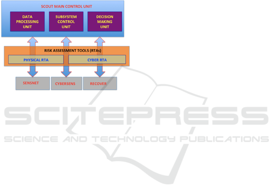
RECOVER for automatic restoration and
intelligence reconfiguration of the space control
ground station network, in the case of fault of
one of the nodes.
Risk assessment tools drive both, design and
system functionality.
This paper focusses on the SENSNET system
and the data link architecture required for the
operation, control and maintenance of the different
sensor networks that belongs to it.
Figure 1: SCOUT system concept.
2 PHYSICAL-SECURITY
SENSOR NETWORK
2.1 Problem Formulation
Nowadays, physical security systems can be
classified into physical-based and remote sensing-
based solutions:
Physical-based systems are composed of sensors
that detect the intruders when they physically
come into contact with the sensor, or when they
are in its near proximity.
They usually require a high number of sensors
(wire, tubes, cables, vibration sensor) distributed
along the fence or in the surrounding perimeter
area; volumetric surveillance is not provided;
installation and maintenance costs are not
negligible.
In remote sensing based systems, the intruder is
detected far from the sensor, which is typically
positioned in a remote site with respect to the
surveillance area.
Two main categories of remote sensing based
systems can be distinguished:
1. Systems operating in the optical and infrared
bands: video motion detection sensors, CCTV
surveillance systems and infrared detection units.
Their main characteristics are the following:
performances are heavily affected by overgrown
vegetation, fog, heavy rain, snow, sand, storm,
animals, debris, and movement of mounting
posts that can be subjected to external
manipulation; air intruder surveillance is not
contemplated; limits for large area surveillance;
low costs.
2. Remote sensing security systems operating in the
microwave region: microwave movement
detectors, radar detection systems. Their main
characteristics are: large area volumetric
protection, including air targets if the radar has a
high elevation beamwidth antenna; all
weather/all day operating; detection of stationary
and moving targets, emission of power (e.m.
pollution, high costs for the presence of the
transmitter, safety of humans subjected to very
high frequency e.m. radiations, high probability
of intercept by Electronic Support Measurement
(ESM) system); possibility of deactivation
through the use of jammers; microwave systems
based on electric field flooding of the
surveillance area are strongly affected by other
electrical fields interferences.
From the above analysis, we can conclude that
remote sensing security systems based on radar
technology are really promising and reliable
solutions. Nevertheless, the radar has the main
drawback that it emits power, and can be easily
intercepted and deactivated by jammers.
Security surveillance is usually limited to a
building, and the ‘attack’ can be recognized only
once it has started. For the reasons above, the
physical security of this critical infrastructure can be
greatly improved by a system that can:
extend the monitored area to the entire building
perimeter, even beyond the fence for terrestrial
and airborne attacks.
anticipate all critical situations (early warning).
preserve the privacy of people not involved in
the buildings normal interactions (limit the use of
image-based systems), since the refinery is a
crowded place.
make use of multiple technologies which are
fault tolerant with respect to light and weather
conditions and that guarantees a suitable level of
redundancy.
intelligently distinguish between people, animals
and inanimate objects.
detect vehicles and obstacles which may hide
dangerous people.
DCCI 2016 - SPECIAL SESSION ON DATA COMMUNICATION FOR CRITICAL INFRASTRUCTURES
140
limit the number of false alarms by properly
filtering only the important information to the
control room operator, in order to preserve the
systems efficiency.
reduce the installation and maintenance costs.
reduce the electromagnetic pollution (the system
must not be invasive).
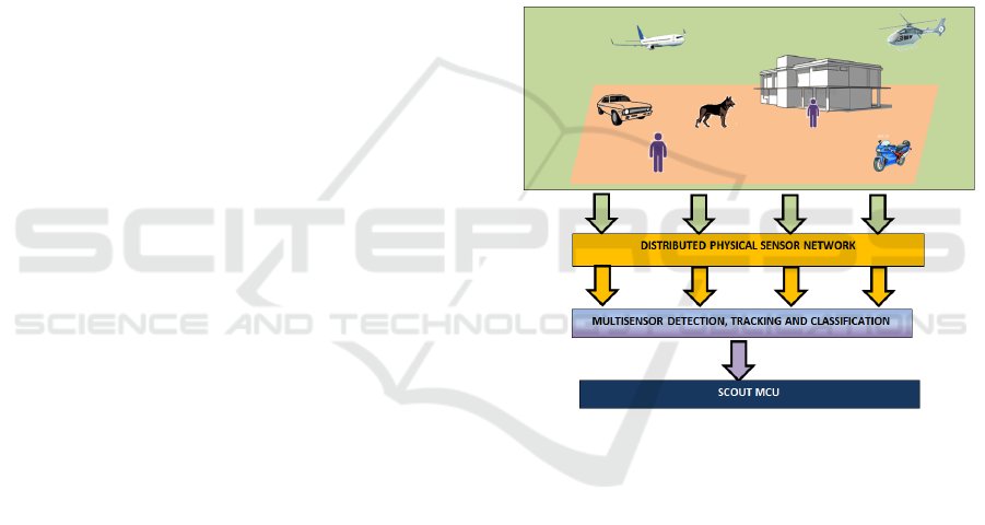
2.2 SENSNET Subsystem
The main functional block of the physical sensor
network SENSNET is depicted in Figure2:
A distributed sensor network interacts with the
surveillance area to acquire information about
the presence of potential physical threats, and
perform a first level detection.
The multi-sensor detection and tracking stage
applies data fusion techniques to improve
detection capabilities of the overall system and
perform target tracking.
Detected targets data will be applied to a
classification stage to discriminate between
aerial targets, terrestrial targets and living things.
Classifier outputs will be delivered to the MCU.
Design drivers combined those defined in section
2.1. and the following:
Detection of stationary and moving targets.
Capability of identifying authorized people and
vehicles.
Reduce the electromagnetic pollution and avoid
the requirement of band allocation: (Royal
Decree, 2001), (ECA Table, 2014), (Mazar,
2014).
Low probability of intercept (LPI).
Reconfigurable, modular, high performance and
robust solutions.
Low power consumption.
Use of data fusion techniques to improve
detection, tracking and classification
performances.
2.2.1 Distributed Physical Sensor Network
The distributed physical sensor network includes
systems operating in the microwave and infrared
regions, and Radio Frequency Identification, RFID,
systems.
Microwave systems selection was guided by the
following goals:
Null or very low power emission.
Fault tolerant with respect to light and weather
conditions.
Capable of performing volumetric protection
(ground and aerial targets), early warning, and
detection of stationary and moving targets.
The proposed solution includes Passive Bistatic
Radars (PBR); noise radars, and radar imaging
sensors for target classification.
Infrared cameras provide target images at high
spatial resolution, also in dark conditions, which are
useful for target classification.
Microwave and infrared imaging system
guarantee the preservation of people privacy.
RFID mounted on friendly people and vehicles
will be used to identify authorized people and
vehicles.
The above sensors are equipped with an own
detector, whose outputs will be a first level of
detection (pre-detections).
Figure 2: Physical sensor network functional block
diagram.
2.2.2 Multi-sensor Detection, Tracking and
Classification
A multi-sensor detector based on data fusion
techniques refines the single sensor plots and
provides the final detections with higher
performance in terms of probability of detection, and
probability of false alarms, by properly filtering only
the important information to the control room
operator, in order to preserve the systems efficiency.
A first level classifier provides a preliminary
classification of unknown targets in three classes:
aerial vehicle, terrestrial vehicle, and possible
humans. Known people detected and tracked by the
RFID system are discarded.
Targets classified as possible humans will be
illuminated by infrared and microwave imaging
Distributed Physical Sensors Network for the Protection of Critical Infrastractures Against Physical Attacks
141
systems to generate images that will be driven to the
second level classifier in charge of classifying into
three classes: humans, animals, and others.
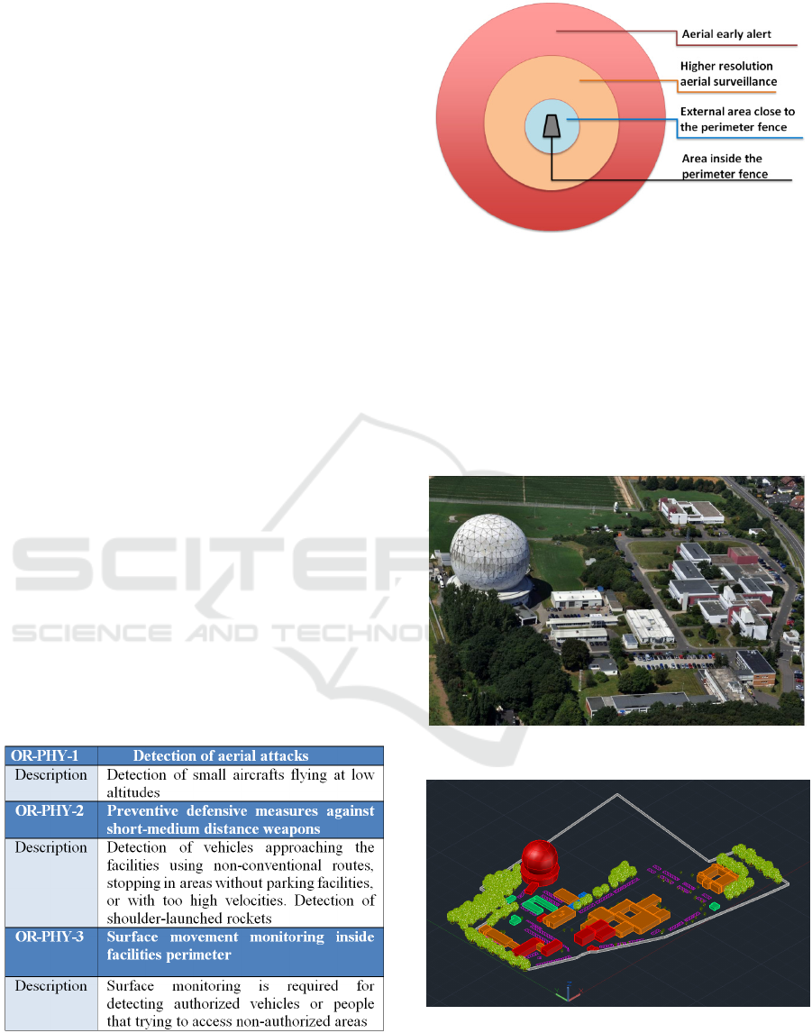
3 SYSTEM REQUIREMENTS
SENSNET operative requirements are summarized
in Table 1. The coverage area is structured in four
sub-areas (Figure 3):
The aerial early alert area defines a ring centred
on the facility central point, and extends from
10km to 20km. The objective is the early
detection of low altitude aerial targets
approaching the facility.
Targets to be sought are big-medium commercial
airplanes and small aircrafts (CESSNA type).
The higher resolution aerial surveillance area
defines a circle centred in the central point of the
facility with a radius of 10km.
Targets of interest are small aircrafts, medium
size (>5m of wingspan) drones, and ultralight
aircrafts with cockpit.
External area close to the perimeter fence,
defined by a radius 2-3 km bigger than the
distance of outermost point of the perimeter
fence from the central point of the facility.
Targets to be sough include aerial ones
(ultralight aircrafts or small drones), medium
distance weapons (shoulder-launched rockets)
and ground vehicles (trucks, vans or cars).
Persons trying to climb or run through the fence
will be also targets of interest.
Table 1: SENSNET operative requirements.
Figure 3: Coverage areas.
4 SCENARIO DEFINITION
The case study is defined on the Tracking &
Imaging Radar (TIRA) system site, located on a
campus shared by the two Fraunhofer Institutes FHR
and FKIE (Figure4). A 3D CAD model was built for
the analysis of shadowed areas (Figure5).
Figure 4: TIRA site.
Figure 5: 3D CAD model of the TIRA site. Colours
represent priority level: high priority (red), medium
priority (orange), low priority (green), parking (pink).
DCCI 2016 - SPECIAL SESSION ON DATA COMMUNICATION FOR CRITICAL INFRASTRUCTURES
142
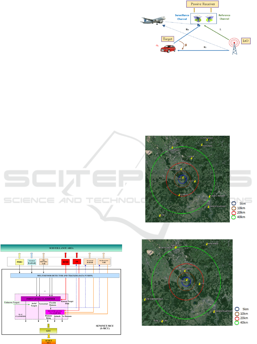
5 SENSNET ARCHITECTURE
SENSNET architecture is depicted in Figure 6. In
the following subsections, SENSNET technologies
are described.
5.1 Passive Radar Network
A Passive Bistatic Radar (PBR) can be defined as a
set of radar techniques that use non-cooperative
signals, such as broadcast, communications, radar,
or radio-navigation signals as Illuminators of
Opportunity (IoO), rather than a dedicated
transmitter (IEEE, 2008). These systems are very
attractive due to their low costs, their low probability
of interception, and low power consumption. The
basic system geometry is shown in Figure7.
A dual channel reception system is required: a
surveillance channel for targets acquisitions, and a
reference one, for capturing the IoO signal. Target
echoes signals will be correlated with Doppler shifted
copies of the reference signal to generate the Cross-
Ambiguity Function, CAF, that will provide
processing gain and the capability of estimating
bistatic range and Doppler of the detected targets.
Digital Audio Broadcasting (DAB) and Digital Video
Broadcasting-Terrestrial (DVB-T) were selected as
IoOs (Coleman, 2008), (Saini, 2005), (Conti, 2010),
(Kulpa, 2011), (Gomez-del-Hoyo, 2015).
Available IoOs in the considered case of study
are shown in Figure 8 and Figure9.
The proposed passive radar node architecture is
based on Software Defined Radar, SDR, principles
(Figure 10). Antenna arrays are used due to the
angular resolutions required by the targets to be
sought, and the coverage requirements.
Figure 6: SENSNET general architecture.
Figure 7: PBR geometry.
Sensor emplacement techniques will be applied
together with the information of the available IoOs
to design the final network architecture.
Beamforming techniques will play a key role,
allowing the generation of multiple radiation beams
in order to fulfill the required instrumented angular
coverage and azimuth resolutions. The first approach
of passive radar network structure is shown in
Figure 11.
Figure 8: Available DVB-T IoOs.
Figure 9: Available DAB IoOs.
Distributed Physical Sensors Network for the Protection of Critical Infrastractures Against Physical Attacks
143
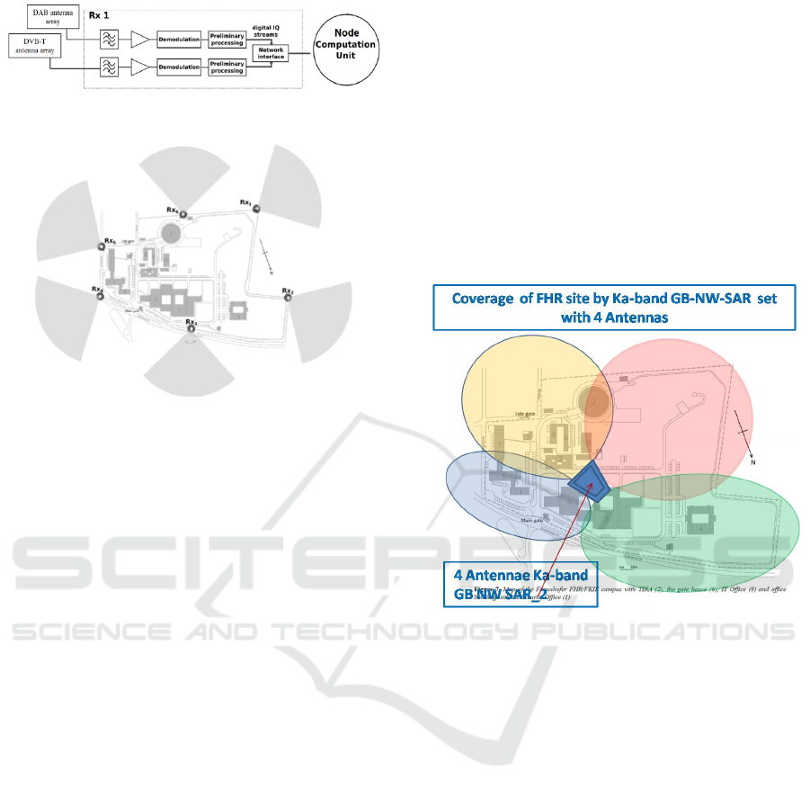
Figure 10: Basic scheme of a PBR node.
Figure 11: First approach of passive radar network
architecture.
5.2 Noise Radar
Noise Radars (NR) use random noise, pseudo-
random or chaotic waveforms as sounding signals,
and coherent processing for target detection. These
signals provide important properties: optimal
coherent reception and high compression rate,
independent control of velocity and range
resolutions, no side lobes in Ambiguity Function, no
range ambiguity for both Continuous Wave (CW)
and pulse radar.
NR enables better performance in LPI, immunity
against interferences and/or jamming, and better
electromagnetic compatibility performance between
different units and different types of radar sensors.
Spectrum sharing problem may be easier solved
using correlation properties of noise waveforms with
wide enough power spectrum bandwidth. Two NR
sensor networks are proposed:
A C-band noise radar network for the detection
of medium distance weapons (shoulder-launched
rockets) and ground vehicles (trucks, vans or
cars) in the external area close to the perimeter
fence, and for complementing passive radars for
the detection of ultralight aircrafts or small
drones approaching the perimeter fence in the
higher resolution aerial surveillance area
(Malanowski, 2012), (Shelevytsky,2013).
A Ka-band Ground Based Noise Waveform SAR
(GB NW SAR) network for the detection of
moving targets in the inside perimeter area, in
combination with RFID sensors, and for
complementing passive and C-band noise radars
for the detection of the most challenging targets
approaching the perimeter fence: ultralight
aircrafts, small drones and persons (Lukin,2008),
(Lukin,2005).
Figure 12 shows a possible Ka-band GB NW
SAR sensor network configuration for the detection
of objects inside the TIRA-site, and others
approaching the main gates or other parts of the
perimeter, being a complement of passive radar and
C-band noise radar networks for the detection of
ultralight aircrafts, small drones and persons
approaching the perimeter fence.
Figure 12: TIRA site coverage with GB NW SAR sensor
network with four antennas.
5.3 Imaging Sensors
Two types of sensors are responsible of target
images generation for classification purposes:
A Ku-band system which operates in real
aperture mode, and can provide high resolution
radar data which can be used with Inverse SAR
algorithms for the generation of the target’s
images (Metasensing. 2015), (Marotti, 2015).
A network of Pan-Tilt-Zoom (PTZ) cameras,
which are characterized by an angular Field of
View, FoV, that can vary along the three
dimensions: horizontal (pan), vertical (tilt), and
depth (zoom). Midwave and Longwave cameras
are used, because they do not require an
illumination source.
5.4 RFID Sensor Network
The goal of the RFID sensors network is to monitor
and track critical people and/or objects in the area
DCCI 2016 - SPECIAL SESSION ON DATA COMMUNICATION FOR CRITICAL INFRASTRUCTURES
144
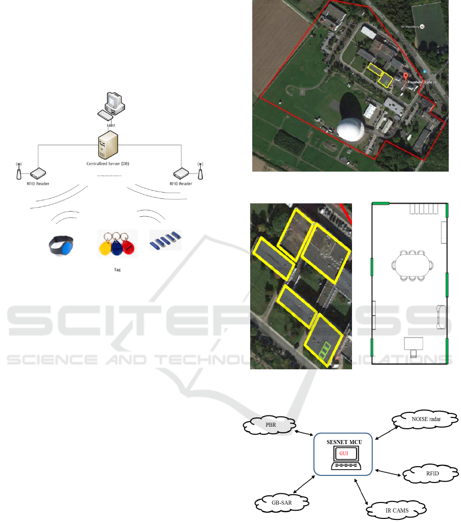
inside the perimeter fence, to avoid that people can
access an unauthorized area without proper
permission (Vitrociset2012).
The data acquired though the sensors will be
managed through a centralized server, connected to
the overall SCOUT infrastructure via a proper link
(Figure 13).
Figure 13: RFID Centralized Data Management.
The system is designed following a hybrid
approach, based on the consideration that the
localization will be divided in two main parts and
that different RFID active transponders can be used:
Outdoor (Figure 14)– the target’s localization is
made with estimation techniques (Received
Signal Strength, Time Of Arrival, Time
Difference Of Arrival, Received Signal Phase,
Angle Of Arrival);
Indoor (Figure 15) – the target’s localization is
made with proximity techniques based on a
dense deployment of antenna.
The proposed architecture can be completely
customized considering the user’s needs and the
Ground Station structure.
6 DATA LINK ARCHITECTURE
A basic communication point-to-multipoint topology
is defined in Figure 16, assuming the SENSNET
general architecture (Figure 6). Each subsystem is
composed by a set of sensors distributed throughout
the facility area that are connected to the MCU. In
Figure 16, each sensor network is represented by a
cloud, although, in each network, each node is
connected to the MCU.
Figure 14: RFID outdoor localization level.
Figure 15: RFID indoor localization level: level 1 (left)
and level 2 (right).
Figure 16: SENSNET communication network basic
diagram.
6.1 Messages Types
According to the information required or provided
by the different nodes, the following types of
messages are defined:
Distributed Physical Sensors Network for the Protection of Critical Infrastractures Against Physical Attacks
145

MCU_Configuration messages: The MCU must
be able to modify sensor subsystem operative
parameters in order to adapt the SENSNET
performance to a changing environment, or to
carry out system updates.
MCU_Management messages: For fulfilling the
second level classifier input constrains, S-MCU
must be able to ask the IR, the Ku-band
radar, and the radiometric SAR sub-systems for
additional information about specific targets.
SENSOR_Data Fusion messages: Detection and
tracking messages will be generated in each of
the nodes belonging to sensor networks
responsible of surveillance tasks for target
detection and tracking: PBR, NOISE RADAR,
Ku-band radar, and RFID. These data will be fed
to the data-fusion and/other first classifier stages,
following the architecture presented in Figure 6.
A common data format must be defined for this
type of messages in order to facilitate the data
fusion process
.
SENSOR_2LClass messages: As answers to the
MCU requests, IR and Ku-band radar
subsystems must provide additional information
related to detections classified as possible
humans.
In order to reduce the required communication
network bandwidth, the direct transmission of the
signals acquired by each node must be avoided. The
use of array antennas and digital beamforming
techniques, impose the use of a dedicated data link
for each single radiating element of each antenna
array, giving rise to an unaffordable transmission
bandwidth if raw data is transmitted to the S-MCU
or to central nodes designed for the processing of
raw data acquired by the nodes of a specific sub-
system (sensor network). Local processing also
enhances the robustness of the SENSNET, because
if one node is attacked, the rest of the nodes will
continue working, and could be reconfigured for
guaranteeing the physical protection of the
infrastructure. So SENSNET will be a distributed
sensor network.
Nodes belonging to sensor networks responsible
for target detection and tracking will perform
detection and tracking tasks and will generate local
SENSOR_DATA_Fusion messages that will be sent
to the S-MCU, more specifically, to the multisensor
detector and tracker. This architecture also improves
real time processing capabilities. As an answer to
MCU_Management messages, the nodes belonging
to sensor networks responsible of providing
additional information to the second level classifier,
will generate local SENSOR_2LClass messages.
6.2 Sensors Data Format
The multisensor detector and tracker module uses
the detection and tracking data generated by each
sensor that belongs to GB-SAR, PBR, and NOISE
radar sensor networks. As additional information,
data provided by the RFID network, mainly
consisting of identification and locations tags, are
also analysed in this data fusion stage in order to
improve system surveillance capabilities.
To facilitate the fusion task, a common data
format shall be defined for monostatic sensors, as
well as for bi/multi-static ones in the Cartesian
domain.
In Table 2-Table 6, data fields of the
SENSOR_Data_Fusion messages are defined:
TypeID defines the type of message.
sourceID identifies the sensor network to which
the node belongs to (the type of node).
rxUid identifies each single node.
trackID. Each SENSNET node is capable of
performing radar observations in either the
Range/Doppler or Cartesian plane. By
associating consecutive observations the node
assigns unique track ID's to target detections.
timeStamp. All nodes are required to give a time
stamp in epoch time, associated to each track ID,
making necessary a clock signal distribution
among the all SENSET nodes.
To accommodate outputs from many different
types of systems, a selection of possible fields is
proposed. The column titled Optional indicates
fields that might not be strictly needed for the fusion
task, or that are redundant if other measurement
fields can be provided, indicating for which sub-
systems that field is required.
IR and Ku-band radar nodes must perform local
classification tasks to distinguish between persons,
animals and others. SENSOR_2LClass messages
will contain the fields defined in Table 2, and
specific fields related to image quality and
classification accuracy (Table3) and target features.
The final data fields will be defined when the signal
processing solutions for classification will be
designed. Specific fields could be defined for IR
nodes, because the transmission payload associated
to IR images is clearly lower than radar ones.
DCCI 2016 - SPECIAL SESSION ON DATA COMMUNICATION FOR CRITICAL INFRASTRUCTURES
146

Table 2: Data exchange format for SENSNET subsystems:
target identification fields.
Detection Identification fields
# Field
name
Unit Description Optional
0 TypeID # MCU_Configuration
(1),
MCU_Management
(2),
SENSOR_Data
Fusion (3),
SENSOR_2LClass
(4), …
No
1
sourceID # Passive Radar(1),
Noise Radar(2), GB-
SAR(3), RFID(4)
No
2 trackID # Unique
Identification of the
track
No
3 txUid # Unique
Identification of
illuminating
transmitter (for
PBR)
Not for
PBR
4 rxUid # Unique
Identification of the
receiver
No
5 timeStamp
sec Unix epoch time
since 1.1.1970 of the
track head
No
Table 3: Data exchange format for SENSNET subsystems:
quality estimation fields.
Quality estimation fields
# Field
name
Unit Description Optional
6 power
dBW Without system
correction
Yes
7 snr_dB
dB Signal to Noise
ratio of the
latest update
Yes
8 probability
Value
from
0.0 to
1.0
Probability of
this target
track.
No (Yes
for RFID)
Table 4: Data exchange format for SENSNET subsystems:
estimated target location fields.
Targets location fields
# Field
name
Unit Description Optional
9 range m Monotstatic range to
receiver (rxUid)
For
PBR
10 detour
m Bistatic range with
respect to rxUid and
txUid (for PBR)
Not for
PBR
11 Doppler Hz Bistatic Doppler
with respect to rxUid
and txUid (for PBR)
Not for
PBR
12 azimuth deg Target azimuth No
angle receiver with
respect to 0° as true
north (rxUid)
13 elevation deg Target elevation
angle receiver with
respect to (rxUid).
Horizont at 0°.
Yes
14 latitude deg Target WGS84
latitude with respect
Yes
15 longitude deg Target WGS84
longitude with
respect
Yes
16 altitude m Target altitude
above sea level
Yes
Table 5: Data exchange format for SENSNET subsystems:
estimated target dynamic fields.
Targets dynamic fields
# Field name Unit Descriptio
n
Optiona
l
17 detourRate
m/s Bistatic
range rate
with
respect to
rxUid and
txUid (for
PBR)
Not for
PBR
18 detourAccelerat
ion
m/s/s Bistatic
range
accelerati
on with
respect to
rxUid and
txUid (for
PBR)
Yes
19 veloVertical m/s Target
climb rate
Yes
20 veloAzimuth
deg/s Change in
azimuth
angle
receiver
with
respect to
(rxUid)
Yes
21 veloElevation
deg/s Change in
elevation
angle
receiver
with
respect to
(rxUid)
Yes
22 veloAcc m/s Accuracy
of the
velocity
measurem
ent
Yes
Distributed Physical Sensors Network for the Protection of Critical Infrastractures Against Physical Attacks
147

Table 6: Data exchange format for SENSNET subsystems:
tracking and plot fields.
Tracking fields
# Field name Unit Descriptio
n
Optio
nal
23 xyz_1_
xyz_2_
xyz_3_
m
m
m
Measurem
ent vector.
Easting,
Northing
and
Altitude
of
position,
referred to
the
receiver
location.
If
lat/lo
n is
given
24 xyzRate_1_
xyzRate_2_
xyzRate_3_
m/s
m/s
m/s
Measurem
ent vector.
Easting,
Northing
and
Altitude
of
velocity,
referred to
the
receiver
location.
Yes
25 detourCov_0__0_
detourCov_0__1_
detourCov_1__0_
detourCov_1__1_
m2
m2/s
m2/s
m2/s2
2x2
Covarianc
e matrix
of the
Range/Do
ppler
track as
detour and
detour
rate
Not
for
PBR
6.3 Physical Network
Given the criticality of the considered scenario, the
most reasonable choice, as far as the transmission
medium is concerned, is represented by wired
connections. Indeed, the use of wireless links would
expose SENSNET to attacks, such as jamming,
posing serious concerns on the robustness of the
system.
Hence, the idea is to rely on Gigabit Ethernet,
also considering that such a technology is most
probably already deployed in the infrastructure to be
protected. It is important to highlight that such a
LAN technology, if correctly configured and
dimensioned, should be able to guarantee the
requested constraints in terms of throughput and
delay.
6.4 Application Layer Protocol
Regarding the application layer protocol, the idea is
to make use of a publish/subscribe framework, able
to automatically deal with the real-time nature of the
produced data.
In this way, there is no need of implementing
“standard” sockets (creating server and clients) for
exchanging the collected data, since the
communication framework directly manages all the
exchanges.
In more detail, the idea is to use the Data
Distribution Service for Real-Time Systems (DDS),
which is an object management group (OMG)
machine-to-machine (m2m) middleware standard
that aims to enable scalable, real-time, interoperable
data exchange between publishers and subscribers.
DDS is networking middleware that simplifies
complex network programming. It implements
a publish/subscribe model for sending and receiving
data, events, and commands among the nodes.
Nodes that produce information (publishers), in our
case the sensors, create "topics" (e.g., location) and
publish "samples". DDS delivers the samples to
subscribers, in our case the S-MCU, which declare
an interest in that topic.
Moreover, DDS allows the user to specify a wide
range of parameters for Quality of Service (QoS)
support, which make it strongly suitable for real-
time communications. Such parameters can be split
into four main categories:
Data availability: decouple applications in time
and space. They also enable these applications to
cooperate in highly dynamic environments
characterized by continuous joining and leaving
of publishers and subscribers.
Data delivery: control the reliability and
availability of data, thereby allowing the delivery
of the right data to the right place at the right
time.
Data timeliness: provide control over the
temporal properties of data.
Resources: provide control over the local and
end-to-end resources, such as memory and
network bandwidth.
6.5 Network Synchronization
The basic proposed clock distribution scheme is
presented in Figure 17. Taking advantage of very
low RTT, typical of Gigabit Ethernet based LAN,
the trusted and well known Network Time Protocol,
NTP, can be used.
DCCI 2016 - SPECIAL SESSION ON DATA COMMUNICATION FOR CRITICAL INFRASTRUCTURES
148

A NTP server could be locally installed in the
MCU in order to exploit the infrastructure and the
network access deployed for data transmission. Most
NTP servers can capture GPS satellite clocks in
order to provide a reliable synchronization time
signal. Then, using the SENSNET network and the
NTP protocol, the time information can be reliably
distributed to all nodes.
Figure 17: SENSNET synchronization time distribution
scheme.
7 CONCLUSIONS
The SCOUT system implements the three main
security functionalities:
1) Physical attack detection and protection.
2) Cyber-attack detection and countermeasures.
3) Automatic restoration and intelligence
reconfiguration of the space control ground
station network, in the case of fault of one of the
nodes.
Sensor networks are used for acquiring
information about potential attacks and/or possible
damages of attacks once inflicted. Taking into
consideration the different characteristics of physical
and cyber intrusions, specific sensor networks are
used for monitoring the physical and cyber
surveillance environments, respectively.
This paper focusses on the physical surveillance
system, describing the main characteristics of the
global network of sensor networks exploiting
different technologies. Main design drivers were:
fault tolerant with respect to light and weather
conditions; capability of identifying authorized
people and vehicles; intelligent discrimination
between people, animals and inanimate objects,
preserving the privacy of people; reduce the
electromagnetic pollution; low probability of
intercept; avoid the requirement of band allocation;
reconfigurable, modular, high performance and
robust solutions, with low installation and
maintenance costs.
The data provided by the sensor networks will be
processed by a Main Control Unit (MCU) to
determine a situation awareness picture, which is
used to assess the degree of alert. If potential threats
are detected, the MCU can order the corresponding
sensor network to focus on tracking it.
Each node of each sensor network will perform
detection or classification tasks, providing processed
data following a defined format. This solution
reduces transmission bandwidth requirements, and
improves robustness against nodes physical attacks
or failures. Considering the security of the
communications as a valuable feature for the
transmission medium selection, wired networks are
in general cheaper and more reliable. Thanks to the
low transmission bandwidth, LAN based on
Gigabyte Ethernet using UTP cable could be
considered.
ACKNOWLEDGEMENTS
The Optoelectronics Laboratory of the Spanish
Aeroespace Institute (INTA) provided a data base of
IR images for the design and validation of the
infrared sensor network.
This work was partially supported by SCOUT, a re-
search project supported by the European
Commission under its 7th Framework Program
(contract-no. 607019). The views and conclusions
contained herein are those of the authors and should
not be interpreted as necessarily representing the
official policies or endorsements, either expressed or
implied, of the SCOUT project or the European
Commission.
REFERENCES
Moore, R., Lopes, J., 1999. Paper templates. In
TEMPLATE’06, 1st International Conference on
Template Production. SCITEPRESS.
Smith, J., 1998. The book, The publishing company.
London, 2
nd
edition.
Critical infrastructure protection in the fight against
terrorism - COM(2004) 702.
EU Cooperation Theme 10 Security Work Programme
2013. (European Commission c(2013) 3953 of 27 June
2013.
Royal Decree 1066/2001, 28th September, Regulations
that define the radio-electric public domain protection
conditions, limitations to radio-electric emissions, and
Distributed Physical Sensors Network for the Protection of Critical Infrastractures Against Physical Attacks
149

health protection measures against radio-electric
emissions.
ECA Table, The European Table of Frequecy Allocations
and Aplications In the frequency range 8.3 kHz to
3000 GHz. Approved may 2014.
Mazar, H., International, regional and national regulation
of SRDs, ITU WORKSHOP on SHORT RANGE
DEVICES (SRDs) AND ULTRA WIDE BAND
(UWB). Geneva, 3 June 2014.
IEEE Standard Radar Definitions, IEEE Aerospace and
Electronics System Society Sponsored by the Radar
System Panel, 2008.
Coleman, C.J., Yardley, H., DAB based passive radar:
Performance calculations and trials, International
Conference on Radar, 2008, pp. 691-694, September
2008.
Saini, R., Cherniakov, M., DTV signal ambiguity function
analysis for radar application, IEE Proceedings on
Radar, Sonar and Navigation, vol.152, no.3, pp. 133-
142, 3 June 2005.
Conti, M., Berizzi, F., Petri, D., Capria A., Martorella, M.,
High range resolution DVB-T Passive Radar, Radar
Conference (EuRAD), 2010 European, Paris, 2010,
pp. 109-112.
Kulpa, K., Malanowski, M., Misiurewicz, J., Samczynski,
P., Passive radar for strategic object protection,
Microwaves, Communications, Antennas and
Electronics Systems (COMCAS), 2011 IEEE
International Conference on, Tel Aviv, 2011, pp. 1-4.
Gomez-del-Hoyo, P., del-Rey-Maestre, N., Mata-Moya,
D., Jarabo-Amores, M.P., First results on ground
targets tracking using UHF passive radars under non
line-of-sight conditions, Signal Processing Symposium
(SPSympo), pp.1-6, June 2015.
Malanowski M., Kulpa, K., Detection of Moving Targets
With Continuous-Wave Noise Radar: Theory and
Measurements, IEEE Transactions on Geoscience and
Remote Sensing, vol. 50, no. 9, pp. 3502-3509, Sept.
2012.
Shelevytsky, I., Kulpa, K., Glushko D., Yanovsky, F.J.,
Short-range C-band noise radar for meteorological
application, Electronics and Nanotechnology
(ELNANO), 2013 IEEE XXXIII International
Scientific Conference, Kiev, 2013, pp. 473-475.
Lukin, K.A., Mogyla, A.A., Palamarchuk, V.P.,
Vyplavin, P.L., Zemlyaniy, O.V., Shiyan, Y.A.,
Zaets, M.K., Ka-band bistatic ground-based noise
waveform SAR for short-range applications. Radar,
Sonar & Navigation, IET, 2008, vol. 2, no. 4, pp. 233 –
243.
Lukin, K.A., Sliding Antennas for Noise Waveform SAR,
Applied Radio Electronics, 2005, Vol. 4, #1, pp. 103-
106.
Metasensing Airborne SAR, available at: http://www.me
tasensing.com/wp/index.php/products/airborne-sar/.
Accessed: 15-05-2016.
Marotti, L., Meta, A., Coccia, A., MetaSensing airborne
radar: X- and Ku-band single-pass digital surface
model generation, Synthetic Aperture Radar
(APSAR), 2015 IEEE 5th Asia-Pacific Conference on,
Singapore, 2015, pp. 184-186.
Vitrociset, A smartphone to navigate the justice of Naples,
June 2012. Available at: http://www.vitrociset.it/.
Accessed: 15-05-2016.
DCCI 2016 - SPECIAL SESSION ON DATA COMMUNICATION FOR CRITICAL INFRASTRUCTURES
150
