
Cooperative Radio Resources Allocation in LTE_A Networks within
MIH Framework: A Scheme and Simulation Analysis
Mzoughi Houda
1
, Faouzi Zarai
1
, Mohammad S. Obaidat
2
, Balqies Sadoun
3
and Lotfi Kamoun
1
1
LETI Laboratory, University of Sfax, Sfax, Tunisia
2
Department of Computer and Information Science, Fordham University, New York 10458, U.S.A.
3
College of Engineering, Al-Balqa Applied University, As-Salt, Jordan
Keywords: LTE-Advanced, Radio Resource Allocation, MIH, LTE-a System Level Simulator.
Abstract: Heterogeneity and convergence are two distinctive features for new generation networks like the Long Term
Evolution-Advanced (LTE-A) system. LTE-A is now being deployed and is the way forward for high speed
cellular services. LTE-A enhancements the four areas of capacity, coverage, inter-cells coordination, and
cost. Improvements in these areas are based on using several technologies. Multiple-Input Multiple Output
along with Orthogonal Frequency Division Multiple Access (MIMO/OFDMA) are two of the base
technologies that are enablers. In addition, self-organizing and optimization (SON) technologies have been
also developed to enable automatic configuration, optimization of network operations, including the 802.21
Media Independent Handover protocol (MIH), which is designed to optimize the vertical handover process.
In this paper, we show the importance of inter-technologies and inter-entities cooperation, which can exploit
heterogeneity as an enabler to improve the system capacity as well as the quality of service (QoS) for users.
We present a new cooperative radio resource allocation scheme for LTE-A network to coordinate better the
utilization of network’s available radio resources. We adopted the MIH framework, in order to facilitate the
exchange between heterogeneous network entities to insure self-configuration of radio resource
management parameters. We worked on allocating the right PRB to the right user at the right time. We also
analyze some existing solutions and evaluate our proposed scheme using simulation analysis. Simulation
results illustrate the performance gains brought by the proposed optimization, especially for average
throughput of macro-cell users comparing to their initial performance within two-tier LTE-A network.
1 INTRODUCTION
Next generation of wireless mobile communication
systems, provides to end users several amount of
multimedia services. Many of these services are too
expensive in terms of resources. In order to deal
with this explosive of resources’ demands, it is
essential to have a huge network capacity. In order
to fulfill such requirement, some technologies are
chosen to be deployed for the next generation of
wireless network, like the LTE-Advanced (ETSI TS
36.300 v10.11.0; Akyildiz et al., 2010) system, such
as MIMO, OFDMA, Beamforming, small cells
enhancements, macro cells enhancements, HetNets,
among others. Coming along with their benefits,
these new technologies introduce new challenges in
radio resource management (RRM) process, which
is the key issue to insure efficient exploitation of the
available radio resources including especially
interference management and resource allocation
(Dehghani et al., 2015). In this paper, we deal with
radio resource allocation in downlink in case of the
LTE_A systems.
Regarding the literature, we find out several
interesting works investigating the problem of radio
resource allocation in OFDMA networks, some of
which are reviewed below. Some works investigated
resource allocation based on an optimization theory
approach (Dehghani et al., 2015; Papathanasiou,
2013; Alavi et al., 2013; Tang et al., 2015) and
others formulate the problem based on game theory
approach about which a survey is offered in
Akkarajitsakul, 2011. In Dehghani et al., 2015, a
radio resources allocation scheme for
MIMO/OFDMA system with the employment of
beamforming technique is suggested. In this work,
users are classified into two groups: interior and
exterior users in the cell. Interior users are those
where the interference term satisfies that the sum of
received signal in all beams is considerably
smaller than the Gaussian noise; all others are
138
Houda, M., Zarai, F., Obaidat, M., Sadoun, B. and Kamoun, L.
Cooperative Radio Resources Allocation in LTE_A Networks within MIH Framework: A Scheme and Simulation Analysis.
DOI: 10.5220/0006041801380145
In Proceedings of the 6th International Conference on Simulation and Modeling Methodologies, Technologies and Applications (SIMULTECH 2016), pages 138-145
ISBN: 978-989-758-199-1
Copyright
c
2016 by SCITEPRESS – Science and Technology Publications, Lda. All rights reserved
considered as exterior users. Then the total number
of PRB is divided onto Q groups (GPRB) with an
equal size. For exterior users, all GPRB are sorted in
decreasing order of power. Next, the set of GPRBs
that will be allocated to exterior users, which is
calculated according to their number in the cell, are
those with the minimum power for all eNodeBs. The
rest of the GPRBs will be automatically allocated to
interior users. In Papathanasiou, 2013, authors
considered imperfect channel state information
(CSI) in the transmitter, which means that CSI is
estimated at the receiver then it is fed back to the
transmitter, and they take into account bit error rate,
rate requirement and delay requirement as QoS
constraints. They proposed a heuristic approach
including three steps. In the first one, the resource
allocation unit decides the number of subcarriers
needed by each user according to the QoS
requirements. Secondly, subcarriers are assigned to
users according to the corresponding power
allocation based on the outcomes of the first step and
power constraint. In the third step, they suggested
the reallocation of some subcarriers according to
user’s satisfaction.
The remainder of this paper is organized as
follows. We give an overview of the present
contribution in section 2. Then in section 3, we
describe the system model used in our study. The
proposed resources allocation scheme is discussed in
section 6 as well as the problem formulation. In
section 5 the simulation results are presented and
analyzed. Finally, section 6 concludes the paper.
2 MAIN CONTRIBUTION
In this paper, we attempt to present a dynamic and
cooperative solution to the problem in order to
satisfy the LTE-A network features. We considered
both network and mobile users constraints. As
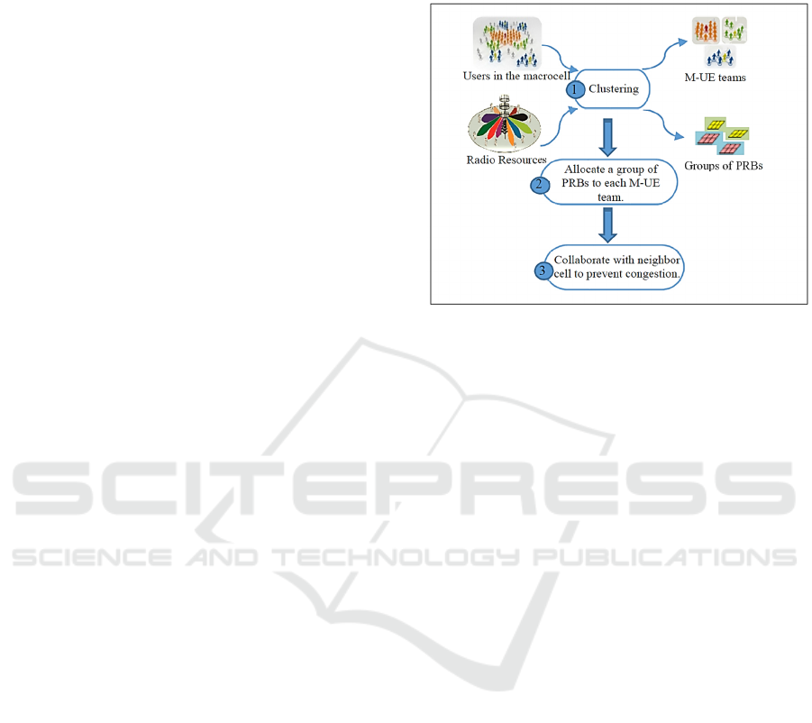
presented in Figure 1, in the first step we classify
users to edge and central users, in both cases users
will be collected to M-UE teams according to their
localization, velocity and QoS requirements. On the
other side, PRBs are assigned by user’s M-UE team.
We estimate the required number of PRBs by each
M-UE team. Then the total available band will be
divided into sub-bands of the required estimated
value and one of them will be assigned to the
corresponding M-UE team of users. The sub-band
selection is based on the resolution of optimization
problem to maximize the capacity provided by the
sub-band for
the
M-UE team of users. We also study
the case when the M-UE team requirement risks
overloading the cell, in such case the cell will
collaborate with neighbors one to serve the group of
users.
Figure 1: Contribution overview.
When developing the proposed approach, we
focus on the selection of the best action by the radio
resources allocation scheme to assign the right sub-
band to the right M-UE team of users at the right
time. We also integrate the congestion control aspect
in order to maintain system stability and users
required QoS. In fact, when the cell becomes close
to overload state, the eNodeB selects a neighbor cell
or one of the existing RAT to collaborate with based
on information collected about different existed
technologies; thanks to MIH deployment (IEEE Std
for Local and metropolitan area networks Part 21,
2008).
3 SYSTEM MODEL
In this work, we investigate radio resource allocation
for multi-cell downlink OFDMA communication
scenario in LTE-A systems. With the OFDM
scheme, the total band is equally divided into P
physical resource blocks (PRBs) and each user can
allocate an integer number of PRBs according to its
requirements. Consider MIMO as key technology of
LTE-A, where each eNodeB is equipped with Me
transmit antennas and users devices are equipped
with M
r
receive antennas. Each eNodeB transmits a
single data stream to each user with zero forcing
beamforming. We mean by M
t ,
the total number of
transmit antennas which is equal to
1
E
i
i
Me
=
∑
where E denotes the total number of eNodeB. Figure
2 illustrates the downlink coordinated beamforming
Cooperative Radio Resources Allocation in LTE_A Networks within MIH Framework: A Scheme and Simulation Analysis
139
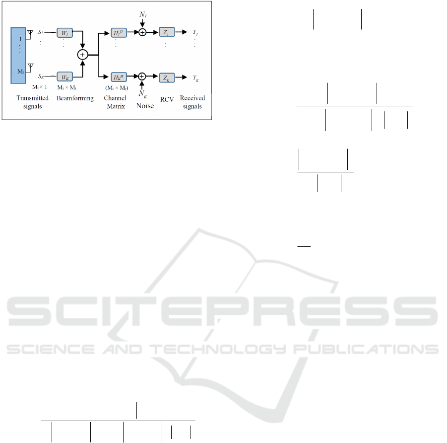
Figure 2: Illustration of downlink coordinated
beamforming.
transmission process. Thus, the received signal
p
k
Y
at user k in the set of K user scheduled in PRB p is
modeled in equation (1) below.
11,j
,,
,,, ,
1
()
EK
E
p
pp p pp p
ijk
p
ji ji
k
ki ki ki ki k
i
YZ HWS HWSN
k
==≠
=
=+ +
∑∑
∑
(1)
Where,
,
p
M
M
re
ki
CH
×
∈
is the channel matrix between
user k and eNodeB i at PRB p.
1
,
pM
e
ji
CS
×
∈
is the data
vector transmitted by the eNodeB i for user j
employing the beamforming vector
1
,
pM
e
ji
WC
×
∈
with
()
,
,
1
H
p
p
ji
ji
SS =Ε
⎡⎤
⎣⎦
.
p
k
N
is the additive white Gaussian
noise with zero mean and covariance matrix σ
2
I
Mr
.
Furthermore
k
Z
denotes the received combining
vector employed at user k. So, the SINR for user k
connected to eNodeB e at PRB p is modeled as
shown below:
2
2
2
2
,
,
,, ,,i
111
,
p
kke
ke
EKE
pp pp
kk
kk
ki ki ki j
iji
ie jk
ZH W
p
SINR
ke
ZH W ZH W Z
===
≠≠
=
++σ
∑∑∑
(2)
Moreover, the interference expression in (2)
includes the interference introduced from other
eNodeBs as well as inter-user interference.
However, with Joint Transmission (Bjornson et al.,
2011), interference between macro and small base
station can be neglected; thanks to the coordination
between all of them when serving all covered users.
In practice, the uncertainty of CSI makes the
cancellation of inter-users interference an impossible
task. The zero forcing beamforming strategy can
give inter-users interference relaxation by being
limited to some threshold value γ>0 instead of being
cancelled (Lee et al., 2011), which means that:
2
,,i
11
KE
pp
kkij
ji
jk
ZH W
γ
==
≠
≤
∑∑
(3)
According to the description above, the SINR at user
k can be formulated as:
2
2
2
2
,
,
2
,,i
11
,
,
,
p
kke
ke
KE
pp
kkk
ki j
ji
jk
p
kke
ke
kk
ZH W
p
SINR
ke
ZH W Z
ZH W
Z
γ
=
==
≠
+σ
≥
+σ
∑∑
(4)
The achieved data rate by user k in its served cell e
for one PRB p is given by:
2,,
1
1
log (1 )
p
p
p
ke ke
N
p
N
RSINR
=
=+
∑
(5)
Where N
p
denotes the number of allocated PRB to
user k in by eNodeB e. And the total system capacity
is modeled as:
,
11
EK
Tke
ek
CR
==
=
∑
∑
(6)
4 RADIO RESOURCES
ALLOCATION
To meet expectations of 5G telecommunication
systems, an efficient resource allocation scheme is
needed, that should be able to provide a capable real
time solution. In this paper, we look to find a
solution of the problem, while maximizing system
capacity and maintaining end users required QoS.
As mentioned above we focus on LTE-A RAT, but
it could be extended to other RATs. Our approach
includes four steps. In the first step, we focus on
active users classified into central and edge users.
For both cases we collect users into M-UE teams to
form what we called M-UE teams, such idea can
replace the deployment of small cells in order to
cancel inter small cell interference. In addition, it
aims to resolve problems with edge users like
interference and Ping-Pong effect. The result of step
2 gives the selected group of PRBs that will be
allocated to each M-UE team of user, based on CQI
SIMULTECH 2016 - 6th International Conference on Simulation and Modeling Methodologies, Technologies and Applications
140

indicator. In this step, we also propose a linear
problem that maximizes the system capacity under
QoS constraints. In next step, we aim to prevent a
congestion state in the cell. Hence, we propose to
collaborate overloaded cells with neighbor ones that
are under-loaded and can serve some M-UE teams
of users. Finally, in the last step we track the
allocation to check whether the M-UE teams
requirements are satisfied or not, or if there is an
over served M-UE teams and both cases need a
reallocation to improve the efficiency; we consider
also new coming call. Next, we describe details of
each of these steps.
Step 1:
In the macro cell, users are classified to edge and
central one. Then, they are collected into groups to
form M-UE teams according to three metric:
localization, user’s application and user’s velocity.
The role of M-UE team leader can be assigned to
one UE at the same time according to an agreement
with the operator. However, this role is not limited
to a single user; another one can fill it when
principal leader is down, in order to maintain the M-
UE team. The number of mobile users by each M-
UE team is fixed taking into consideration the
capacities of the leader equipment.
Algorithm 1: M-UE Teams Conception.
Initialization
L: List of active users in the sector/cell
B: Number of M-UE teams, B=0
V
k
: Velocity of user k
R
av
: Available data rate
RR
k
: Required rate by user k
while Stop=false
if length (L) >1
a. Select a leader l, L= L/{l}, B = B +1
b. Define the max number of user in the M-UE
team N
max
while i< N
max
and k≤ length (L)
if | V
k
–V
l
|< threshold
Add the mobile terminal to the M-
UE team.
L= L/{k}
i=i+1
end
k=k+1
end
if i< N
max
Stop=true
end
else
Stop=true
end
end
for b=1 to B
for k=1to N
#N is the number of user in the team
if | V
k
–V
l
|> threshold
So this user will be removed from the
M-UE team
end
end
while i< N
max
and k≤ length (L)
if | V
k
–V
l
|< threshold
if RR
k
< R
av
Add the mobile terminal to the M-
UE team.
R
av
= R
av
- RR
k
L= L/{k}
i=i+1
end
end
k=k+1
end
Liberate unused resources
end
The radio resources allocation for each M-UE team
of users will be communicated with the eNodeB by
the team leader only, which will decrease
signalization traffic in the cell.
Step 2:
In the network side, we work on the selection of the
best radio resources to be allocated to each M-UE
team of users. Therefore, the first issue is the
estimation of the number of required PRBs by all
users in the M-UE team, according to the required
QoS for each user in the team, which depends on the
type of traffic. In our work, we considered both real-
time and non-real-time traffic (Rysavy). For users
with real-time applications, fixed rate are required
and for those with non-real-time services only
minimum rate requirements are demanded.
The required number of PRBs for user i is
calculated as follow:
i
i
PRB
R
R
n
R
=
⎢
⎥
⎢
⎥
⎣
⎦
(7)
With
⎣⎦
a
denotes the floor of the fraction, RRi
denotes the required rate of user i and R
PRB
denotes
the peak capacity of one PRB. Assume 64QAM
modulation without coding, over 2 time slot (1ms)
a single PRB has 12 subcarriers and 14 symbols, or
Cooperative Radio Resources Allocation in LTE_A Networks within MIH Framework: A Scheme and Simulation Analysis
141

12 x 14 = 168 resource elements (REs). Some of
those REs are occupied by the PDCCH and the
downlink reference signals, leaving about 120 REs
per PRB to carry data on the downlink. And with
64QAM each RE holds 6 data bits, so the maximum
data rate delivered by one PRB is equal to:
720 /
PRB t
RM Kbs=×
(8)
Then the total number of required PRBs of the M-
UE team k is equal to:
ki
i
Nn=
∑
(9)
Next, the available band will be divided into sub-
bands each one with a number of successive PRBs
equal to the estimated number of required PRBs.
Our goal is to maximize the cell capacity.
Mathematically, we can present this maximization
problem as:
{} {}
{}
{}
2
,,i
11
1.. E 1.. K
1
2,
3,
4
1.. K
1..
,
maximize
C : ,
C :
C:
C: C
,
,
T
KE
pp
kkij
ji
jk
T
RT
NRT
threshold
RT
ki RT
NRT
ki NRT
K
ZH W j
k
k
C
subject to
i
R
R
C
γ
γ
γ
==
≠
∈
∈
∈
≤∀∈
∀
∀
=
≥
≤
∑∑
(10)
Algorithm 2: PRB Allocation.
Result: Obtain the group of PRBs G
b
*
to be
allocated to each M-UE team b.
Input: Available bandwidth
Input: User’s M-UE teams list with leader
localization and QoS requirements for each M-UE
team.
For each M-UE team b
1. Define Set of users with real time services
Define Set of users with non real time services
2. Initialize G
b
*
3. Resolve the problem (10)
End for
Update the available bandwidth to B= B- G
b
*
If B <=threshold
Execute the MIH collaborated cell
B= available bandwidth in the new collaborated cell
End
The selected GPRB will be allocated to the
correspondent M-UE team of users. In order to
maximize system throughput, we adopt downlink
beamforming vector for each GPRB (Alavi et al.,
2013) and also for each M-UE team of users.
Step 3:
This step is executed by the MIIS server, which aims
to form a group of cooperative heterogeneous cells
to extend the available capacity. Heterogeneity here
describes not only macro or small cells, but also
different radio access technologies deployed by the
operator in the area, which explain our choice of
using MIH technology (IEEE Std for Local and
metropolitan area networks Part 21, 2008) to ensure
a simple communication between heterogeneous
network equipment. The selection of a collaborative
cell or collaborative RAT is mainly based on the
load of each. This step is executed when one of the
LTE cell risks depleting its available resources,
which can lead to a congested cell. In order to
prevent such scenario, the MIIS is charged to collect
information about all neighbors of the current cell in
a limited area. Then, it communicates the list of
candidates to the eNodeBs. If the eNodeBs find
LTE-A cell among the candidates list, it will be
selected automatically to establish a collaboration
with through direct communication between
eNodeBs via X2 interface. Otherwise, one of the
least loaded RAT takes the place, and the two
stations will exchange direct messages; thanks to the
MIHF sub layer. We called the selected cell/RAT
the “grandmother cell/RAT”, because all new
connections in addition to some M-UE teams, if
needed, will be served by the “grandmother
cell/RAT” via the intermediate of the mother cell
which is considered like a remote node when serving
new calls/or handover. As soon as possible, the
mother eNodeBs interrupt the connection with the
“grandmother cell/RAT” and continue by itself to
serving all connected users.
Following, is the detailed algorithm for the inter-
cell/RAT collaboration establishment executed by
the eNodeBs.
Algorithm 3: MIH-Cooperation management.
e
c
: Current eNodeB
C
ec
: Available capacity in the current LTE-A cell
MIH-RR-Coop: list of cooperative cells/RATs
C
MIH-RR-Coop
: Total available capacity of the
cooperative
group of cells/RATs
Initialization:
MIH-RR-Coop ={e
c
};
C
MIH-RR-Coop
=C
ec;
Stop=false;
SIMULTECH 2016 - 6th International Conference on Simulation and Modeling Methodologies, Technologies and Applications
142

While C
MIH-RR-Coop
< threshold and Stop=false
♦ Sending a request to MIIS for searching a
cooperative cells
♦ Neighbors’ capacity state request
♦ Select under loaded LTE cells / RATs
♦ Response by the list of candidate L
c
sorted
in ascending by load
If L
c
not empty
• Select the first cell/RAT in the list
• Establish collaboration via X2 or MIH.
• C= C + available capacity in the
collaborative cell
• MIH-RR-Coop = MIH-RR-Coop
∪{selected cell}
Else
Stop=true
end
End
If stop=true
Reject new call
Decrease the rate for some users
End
End.
We define a new MIH primitive of service “MIH-
Cooperate.req” to be exchanged between the MIH
information server and the eNodeBs to ensure the
collaborative resources allocation between LTE-A
macro-cells. This primitive has as a parameter the
minimum required capacity and we use also the
users’ applications to verify that they are supported
or not. The syntax of this primitive is given follow:
MIH-Cooperate.req:
{Available capacity
Users applications }
Step 4:
This step deals with allocation track to see if there is
over served M-UE teams, so as to withdraw unused
resources to be reallocated to underserved M-UE
teams or to incoming calls independently or seeing
the possibility to include new users to one of the
existing M-UE team according to the proposed
scheme described above. We also take into account
resources as soon as they become available after a
terminal leaving.
5 SIMULATION RESULTS
This section illustrates simulation results to evaluate
our proposed algorithms in terms of system
throughput. We worked with the Matlab-based LTE-
A System Level simulator developed by the TU
Wien Telecommunications Institute (Mehlfuhrer et
al., 2011). The simulator allows both link level and
system level simulations. We used also the Matlab-
based convex modeling framework CVX (Becker et
al., 2011) for the resolution of the optimization
problem (10). The LTE-A system parameters used in
simulations are presented in Table 1.
Table 1: Simulation Parameters.
Parameter Description
Duration of simulation 200 TTIs
Number of users per macro cell
100 UEs/MC;
591 in total
M
r
4
M
t
2
User velocity 5m/s
Cell radius 250m
System bandwidth 20 Mhz
Number of PRBs 100 RBs
PRB Bandwidth 180 KHz
Real time requirement [11] 384 kbps
Non real time requirement [11] 32 kbps
In this paper, we compare results of two simulated
scenarios:
• An interfered system and no optimization is
performed with femtocell deployment only;
• An interfered system with joint MUE-team and
femtocell deployment.
First result is shown in Figure 3 that depicts the
empirical Cumulative Distribution Function (CDF)
for all users’ throughput to compare performance
when considering macrocells and femtocells with
and without the integration of our optimization
algorithms. We observe that MUE-teams
deployment besides femotocells offer a higher
average throughput in comparison to the initial
configuration. Indeed, the maximum achieved
throughput when deactivating the proposed
optimization algorithms is about 9.4 Mb/s. While,
when performing our algorithms 20% of users
exceed this value with the possibility of achieving
11.8 Mb/s.
Figure 4 shows performance of scheduling SINR
in form of the empirical CDF when performing the
proposed schemes. By examining the curve we
conclude that, for 90% of users our scheme is able to
find a better choice of resources allocation than with
the initial configuration case.
Cooperative Radio Resources Allocation in LTE_A Networks within MIH Framework: A Scheme and Simulation Analysis
143
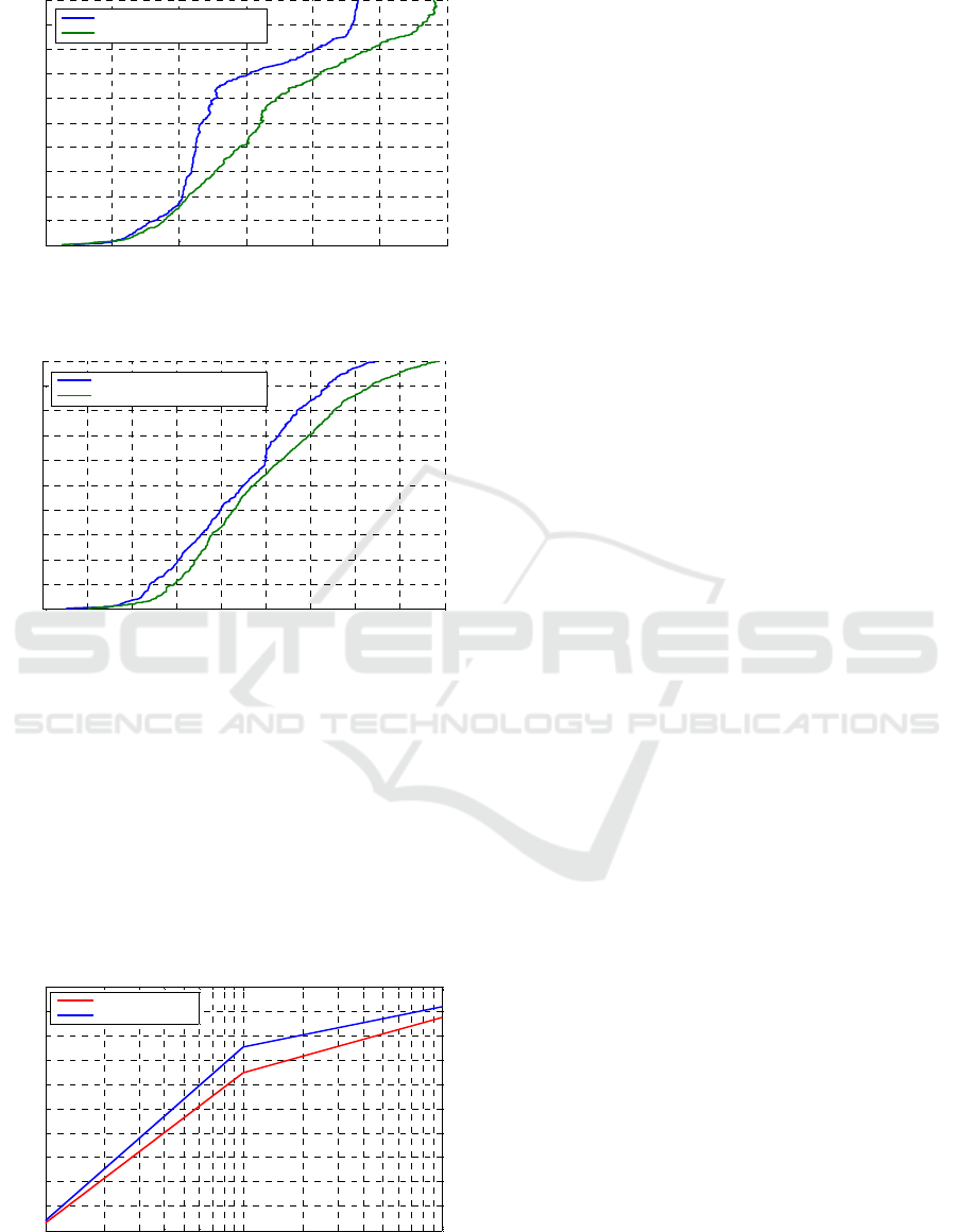
Figure 3: Empirical CDF of global throughput.
Figure 4: Wideband SINR.
Figure 5 shows the variation of the average
throughput in the macro cell with the interference
threshold value when using our scheme. This
performance is presented for two different
concentrations of femotocells. For each simulation
run, we fixed three values of threshold interference
when maintaining the same configuration. We can
clearly observe that there is no major difference
between the two cases, even more femotocells
means more interference inside the macro cell.
Figure 5: Average throughput vs. interference threshold.
We can conclude that our optimization solution
maintains the UE throughput level in various
densities of small cells.
6 CONCLUSIONS AND
PERSPECTIVES
We developed in this paper a cooperative RR
allocation approach for LTE-A systems as multi-
RAT environment and highlight the importance of
inter-cell and inter-RAT cooperation. The proposed
solution makes the heterogeneity an enabler to
improve system capacity. We also provide a new
way to manage active mobile users in the macro cell,
in order to minimize inter user’s interference and
improve their QoS. We further propose a novel
PRBs selection and allocation technique that
optimizes resources exploitation. Simulation results
show that the proposed scheme maximizes the
system throughput while guaranteeing QoS for
users. As future work, we attempt to integrate new
features like D2D communication technique inside
MU-teams. We also intend to deploy radio network
virtualization in order to extend system capacity.
REFERENCES
ETSI TS 36.300 v10.11.0, “LTE; Evolved Universal
Terrestrial Radio Access (E-UTRA) and Evolved
Universal Terrestrial Radio Access Network (E-
UTRAN); Overall description; Stage 2”, (3GPP TS
36.300 version 10.11.0 Release 10).
Akyildiz I. F., Gutierrez-Estevez, D. M and Chavarria
Reyes, E., “The evolution to 4G cellular systems:
LTE-Advanced,” Physical Communication, vol. 4, no.
3, pp. 217-244, December 2010.
Dehghani, M., Arshad, K. and MacKenzie, R., “LTE-
Advanced Radio Access Enhancements: A Survey,”
Wireless Personal Communications, vol. 80, no. 3,
2015, pp. 891-921, February 2015.
Papathanasiou, C., “Dynamic radio resource and
interference management for MIMO-OFDMA mobile
broadband wireless access systems,” Computer
Networks, vol. 57, no. 1, 2013, pp. 3-16, January 2013.
Alavi, S. M., Zhou, C. and Gen, W. W., “Efficient
resource allocation algorithm for OFDMA systems
with delay constraint,” Computer Communications,
vol. 36, no. 4, pp. 421-430, February 2013.
Tang, J., So, D. K. C., Alsusa, E. et al., “Resource
Allocation for Energy Efficiency Optimization in
Heterogeneous Networks,” IEEE Journal on Selected
Areas in Communications, vol. 33, no. 10, pp. 2104-
2117, October 2015.
0 2 4 6 8 10 12
0
0.1
0.2
0.3
0.4
0.5
0.6
0.7
0.8
0.9
1
4x2 MiMo: 20 MHz bandwidth, interfereence threshold=10e-9
UE throughput (Mbit/s)
UE throughput ECDF
femtocell initial configuration
femotocell+proposed optimization
-15 -10 -5 0 5 10 15 20 25 30
0
0.1
0.2
0.3
0.4
0.5
0.6
0.7
0.8
0.9
1
4x2 MiMo: 20 MHz bandwidth,interference threshold=10e-9
UE SINR [dB]
ECDF
initial femtocell configuration
femotocell+ proposed optimization
10
-10
10
-9
10
-8
4
4.2
4.4
4.6
4.8
5
5.2
5.4
5.6
5.8
6
4x2 MiMo: 20 MHz bandwidth
interference threshold [W ]
Average throughput (Mbit /s)
3 Femotocell/km2
7 Femotocell/km2
SIMULTECH 2016 - 6th International Conference on Simulation and Modeling Methodologies, Technologies and Applications
144

Akkarajitsakul, K., Hossain, E., Niyato, D. et al., “Game
Theoretic Approaches for Multiple Access in Wireless
Networks: A Survey,” IEEE Communications Surveys
and Tutorials, vol. 13, no. 3, pp. 372-395, Mars 2011.
IEEE Std for Local and metropolitan area networks Part
21: Media Independent Handover Services. IEEE std
802.21, 2008. (Available from: http://www.ieee802.or
g/21/doctree/Temp/P802-21-D11.pdf).
Bjornson, E., Jalden, N., Bengtsson, M., and Ottersten, B.,
“Optimality properties, distributed strategies, and
measurement-based evaluation of coordinated
multicell OFDMA transmission,” IEEE Transactions
on Signal Processing, vol. 59, no. 12, pp. 6086–6101,
December 2011.
G. Lee, J. Park, Y. Sung, and M. Yukawa, “Coordinated
beamforming with relaxed zero forcing,” International
Conference on Wireless Communications and Signal
Processing, November 2011.
Rysavy, P. “EDGE, HSPA, LTE: The Mobile Broadband
Advantage” [Online].(Available from:
http://www.rysav
y.com/Articles/2007_09_Rysavy_3GAmericas.pdf.).
Mehlfuhrer, C., Ikuno, J. C., Šimko, M., Schwarz, S.,
Wrulich, M. and Rupp, M., “The Vienna LTE
Simulators - Enabling Re-producibility in Wireless
Communications Research”, EURASIP Journal on
Advances in Signal Processing, July 2011.
Becker, S., Candès, E. J. and Grant, M., “Stanford
University Technical Report,” Mathematical
Programming Computation, vol.3, no. 3, August 2011.
(Available from: http://cvxr.com/tfocs/paper/).
Cooperative Radio Resources Allocation in LTE_A Networks within MIH Framework: A Scheme and Simulation Analysis
145
