
Ontological Approach to Share Product Design Semantics for an
Assembly
Baha Hasan
1
, Jan Wikander
1
and Mauro Onori
2
1
Machine Design Department, KTH University, Brinellvägen 85, Stockholm, Sweden
2
Department of Production Engineering, KTH University, Brinellvägen 68, Stockholm, Sweden
Keywords: Assembly Semantic, Assembly Feature, Feature-based Modelling, Ontology, Computer Aided Design
(CAD).
Abstract: The aim of this paper is to facilitate the transfer of product data semantics from Computer Aided Design
(CAD) program to assembly process planning (APP) in product life- cycle. In this paper, an approach to
capture, share and transfer assembly design semantic data from SolidWorks (SW) CAD software to
assembly device (robot Sony SRX series) is proposed. The proposed approach is based, on its first stage, on
defining and extracting assembly design semantics from a CAD model using SolidWorks Application
Programmable Interface (SW- API). The second stage of the proposed approach includes sharing and
integrating the extracted assembly design semantics with assembly robot device by using three-layer
ontology structure. In this layered ontology, different types of ontologies are proposed for each layer:
general foundation ontology for the first, domain ontologies for the second and application ontology for the
third. Each of these layers aids in defining concepts, relations and properties in assembly design domain and
APP domain. Ultimately, the proposed ontology will be used to integrate both domains in product-life cycle.
1 INTRODUCTION
During the last decades, the necessity of data sharing
and integration among different users and
applications in product-life cycle has been increased.
For example, the product / assembly design semantic
data stored in a specific CAD model needs to be
delivered to different CAD softwares or to be
analyzed by different softwares.
Two methods have been proposed to facilitate
product / assembly design data transfer among
different applications and users: external and
internal (Miao et al., 2002). In external method
product data is transferred using a standard neutral
data format, such as IGES or STEP, while in the
internal method API (application programmable
interface) functions have been used to recognize and
extract product design data from CAD model. Both
methods have some limitations in sharing product /
assembly data. In both methods data has been
transfer from user to user or from application to
application but not from domain to domain. Another
limitation is the data lost during conversion from
one format to another format in the external method
and the syntactical transfer of data in the internal
method. In order to overcome those limitations,
ontology approach to share product / assembly
design semantics has been proposed.
Recently, the ontology and semantic Web
technology has been widely applied in integrating
product design and different applications in product-
life cycle. Ontology can be regarded as “a data
model that represents a domain and is used to
reason about the objects in that domain and
relations between them” (Gruber, 1993). Ontologies
have been used to capture and share product design
knowledge, to integrate engineering applications and
to solve interoperability problems (Patil et al., 2005).
Ontologies specify “a domain-specific vocabulary of
entities, classes, properties, predicates, and
functions, and a set of relationships that necessarily
hold among those vocabulary items” (Fikes and
Farquhar, 1999). Ontological approach has been
used either in modelling or retrieving product /
assembly design semantics generated during design
process. By ontology querying, data can be retrieved
and by ontology reasoning, data that are not
expressed explicitly can be derived from the
ontology.
In this paper, a proposed approach, based on
ontology, to integrate SolidWorks (SW) CAD
104
Hasan, B., Wikander, J. and Onori, M.
Ontological Approach to Share Product Design Semantics for an Assembly.
DOI: 10.5220/0006051701040111
In Proceedings of the 8th International Joint Conference on Knowledge Discovery, Knowledge Engineering and Knowledge Management (IC3K 2016) - Volume 2: KEOD, pages 104-111
ISBN: 978-989-758-203-5
Copyright
c
2016 by SCITEPRESS – Science and Technology Publications, Lda. All rights reserved
software in assembly design domain and assembly
robotic device in Assembly Process Planning (APP)
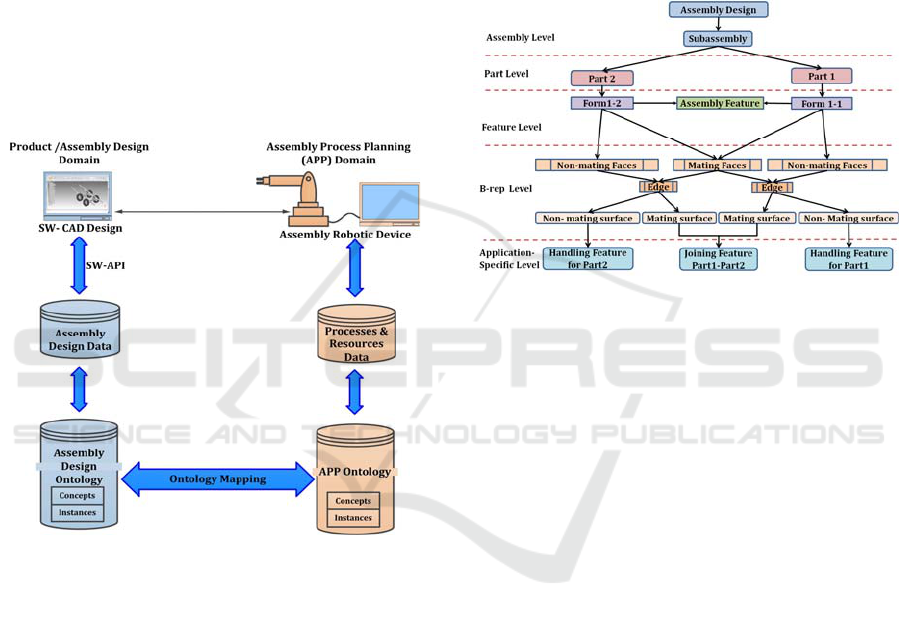
domain is introduced. The integration framework of
the proposed approach is illustrated in Figure.1. In
Figure 1, the first stage of integration is to extract
and model assembly design data from SW- CAD in
assembly design domain (using SW- Application
Programmable Interface (SW-API)), and processes
and resources data from assembly robotic device in
the APP domain. The second stage includes sharing
the extracted assembly design data by assembly
design ontology and processes and resources data by
APP ontology. The integration of the assembly
design domain and APP domain will be achieved by
ontological mapping between assembly design
ontology and APP ontology, which represents the
third and last stage in the integration framework.
Figure 1: Integration framework between assembly design
and APP.
This paper is mainly focused on the first and
second stages of the integration framework. This
paper is structured as follows: Section 2 introduces
briefly assembly design semantic model based on
assembly features. Section 3 introduces the proposed
ontology for sharing the extracted semantic data
from the previous section, and integrating SW CAD
software with assembly robotic device. Section 4
draws a conclusion and provides a summary.
2 ASSEMBLY SEMANTIC
MODEL
The most representative assembly design modelling
methods are based on features (Shah and Rogers,
1993), constraints (Ma et al., 2004) and assembly
semantics (Liu et al., 2000). According to Liu et al.
(2000) assembly semantics is defined as “the
abstract description of assembly relationships,
which implies the constraint between parts,
assembly rule, assembly knowledge and assembly
action”. In this paper, assembly semantic model,
based on features, is developed (Figure 2) to model
assembly design data extracted from SW- CAD
software.
Figure 2: Assembly design semantic model.
In Figure 2, a multi-level assembly semantic
model is illustrated; each layer conducts different
details about assembly design. Assembly and part
levels concern about structural information of an
assembly, each product is composed of several
subassemblies, and each subassembly is composed
at least from two parts. The feature level is
concerned about geometrical and assembly
knowledge enclosed in form and assembly features.
Assembly feature is defined as an association
between two form features from different parts in a
product (Shah and Rogers, 1993), where form
feature is defined as “specific configurations on
surfaces, edges, or corners of a part such as holes,
slots etc. that carries some engineering meaning”
(Wingard, 1991).
Each part is composed at least of one form
feature, which is associated with another form
feature, from different part, via an assembly feature.
The next B-rep entity level conducts more specific
knowledge about geometrical entities involved into
assembly relation. B-rep modelling decomposes a
solid into its boundary surfaces or shells. Each shell
can be decomposed into individual faces. Each face
is described as a surface bounded by a loop of edges.
Each edge is bounded by two vertices. In the B-rep
level, each form feature is composed from mating
faces (faces with assembly relations) and non-
Ontological Approach to Share Product Design Semantics for an Assembly
105
mating faces (faces that are not involved in any
assembly relation). Mating and non-mating faces are
decomposed further into mating surfaces and non-
mating surfaces. The last level, which is the
application-specific level, will assign specific
functional features for each surface type to perform
assembly processes.
Mating surfaces will be involved in joining
processes (welding, screwing, fitting, etc.) so they
will be a part of joining features, which are proposed
by (Kim, 2003) to represent assembly/joining
relations, and it includes joining entities, joining
methods, constraints and groove shapes. The non-
mating surfaces will be involved in handling
processes (gripping, feeding and fixturing) so they
will be known as handling features- “characteristics
that give the locations on an assembly component
that can be safely handled by a gripper during
assembly!” (Van Holland, 1997). Further
illustration for the concepts of the assembly
semantic model is presented in peg and though-hole
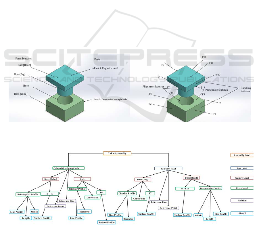
cube assembly example in Figure 3, the assembly
semantics are illustrated in Figure 4 as well.
In Figure 3, a two-part assembly (part 1:
rectangular head peg and part 2: cube with through-
hole) is presented. The parts and form features of the
assembly are indicated in Figure 3 a. In Figure 3 a,
part 1 consists of two form features: the head and the
peg. Part 2 consists also of another two form
features: the hole and the cube. In Figure 3b, the
two-part assembly is further decomposed into its
elementary boundary faces (B-rep entity). The
mating faces are indicated as plane mate features for
rectangular faces (F13- F5) and alignment feature
for cylindrical faces (F7 –F6). An example about
handling features selected from the non-mating
surfaces is also indicated (F12 from part 1 and F1
from part 2). The assembly semantic model for the
two-part assembly is illustrated in Figure 4. A six-
layer semantic model is presented, where the first
layer is for the assembly, which is composed of parts
and features in the second and third layers. The
features are composed of the B-rep entities like
faces, profile, centerlines, and so on in the fourth
layer. The last two layers are for position/orientation
and geometrical dimension and tolerances (GD&T).
The position layer consists of reference line and
reference point for each part, while the GD&T layer
consists of dimensions and tolerances for each B-rep
entity
Assembly data semantics include well- definition
and usage of assembly design data. Practically,
(a) (b)
Figure 3: (a) Peg and though- hole cube assembly, parts and features (b) Peg and though- hole cube assembly, faces
assembly features.
Figure 4: Assembly semantic model for the two-part assembly.
KEOD 2016 - 8th International Conference on Knowledge Engineering and Ontology Development
106
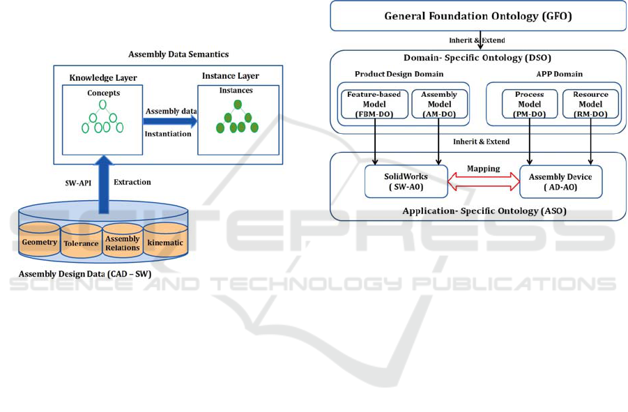
assembly data semantics, which is built upon
assembly data, is represented by two layers:
knowledge layer and instance layer. The knowledge
layer describes the basic knowledge within any
domain by using a set of generic concepts, relations
between those concepts and axioms applied on
relations. The instance layer, which is more specific
layer, links product data into the knowledge layer by
instantiating concepts of the knowledge layer. Figure
5 shows our proposed approach to create product
data semantics by extracting product data (geometry,
tolerance, kinematics and assembly design) from
SW- CAD software using SW-API. The relation
between the knowledge layer and instance layer is
illustrated as well.
Figure 5: Relationship between assembly data and
assembly data semantic knowledge and instance layers.
3 ONTOLOGY DEVELOPMENT
The literature points out that a significant amount of
work has been done on the use of ontologies either
to model assembly design data or to support
integration between design and process in assembly.
Lohse et al. (2006) proposed ontology to support
selection of assembly resources and to support
reconfigurablility of assembly system. Lanz et al.
(2008) proposed ontology to capture design and
process related assembly knowledge based on
assembly feature concept. Delamer and Lastra
(2006) developed an ontology to model assembly
processes. Kim et al. (2003) proposed an assembly
design ontology to support formalism of related
assembly knowledge in product design. Demoly et
al. (2012) proposed an ontology to capture the
product design and assembly sequence planning
knowledge. Mostefai et al. (2006) proposed
ontology to capture the product design data to
support the product development process. Zhan et al.
(2008) and Zhu et al. (2009) proposed layered
structure ontologies to integrate product design and
assembly simulation.
In this paper, a three-layered architecture of
engineering ontologies in product design and APP is
proposed (Figure 6). The proposed structure layered
ontology consists of:
General Foundation Ontology (GFO)
Domain Specific Ontology (DSO)
Application Specific Ontology (ASO)
Figure 6: Three-layered architecture of engineering
ontologies in product design and APP.
The GFO is the first upper layer ontology, which
is designed to provide common concepts, such as
product, feature, material, process, and resource
which are inherited by the DSOs such as FBM-DO,
AM-DO, PM-DO and RM-DO. The Domain
Specific Ontologies represent the second level of the
proposed architecture; those ontologies will add
domain-specific concepts which belong to that
particular domain. The third level is the ASOs (such
as SW-AO and AD-AO); those ontologies will
capture semantics specific to each application. Two
applications have been included: SolidWorks as
product design application and assembly robotic
device (ex. high speed assembly robot Sony SRX
series) as APP application. The knowledge transfer
between different ASOs can be accomplished
through mapping procedures which discovers similar
or matching concepts and properties.
All of the ontologies are implemented by using
the Protégé-OWL editor. In the following
subsections; the three different ontologies of the
layered ontology structure will be discussed.
Ontological Approach to Share Product Design Semantics for an Assembly
107
3.1 General Foundation Ontology
(GFO)
Foundation ontologies consist of generic, abstract,
and high level concepts which can be applied to a
wide range of domains. Foundation ontologies also
provide a knowledge base for more specialized
ontologies (Sanchez-Alonso and Garcia-
Barriocanal, 2006). The GFO contains the general
key concepts, which are common and applied to any
of the domains in product design and APP. The
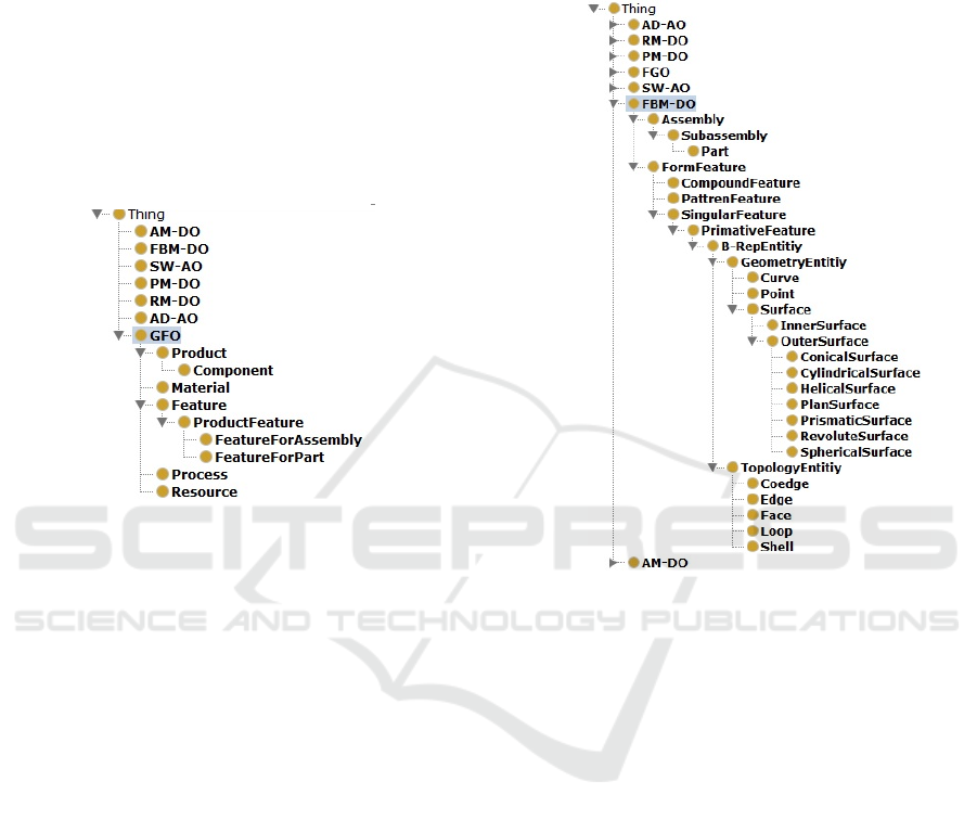
concepts defined in GFO are product, feature,
material, process, and resource (see Figure 7).
Figure 7: Class hierarchy and concepts of the GFO.
The concepts in the GFO ontology have
attributes, which will be inherited by the different
domain ontologies. For example, the Component
subclass, which describes the basic structural design
entity under the product class, will be further
inherited by FBM-DO and SW-AO. FBM-DO will
further embody Component with Assembly,
Subassembly and Part subclasses. The same will be
applied to the Feature class and its subclasses:
FeatureForPart and FeatureForAssembly, which
will be further inherited by the FBM-DO and SW-
AO. The properties defined in FGO are: is-a, is-a-
part-of, is-composed-of and has-attribute-of. The
first two properties reflect the inheritance relations
between different concepts. The last two properties
define the relations between concepts and its
attributes. Each of these ontologies will be discussed
in the following subsections.
3.2 Domain Specific Ontology (DSO)
The DSO layer consists of four domain ontologies
(DO). Two of those are in the product design
domain, namely the Feature-based Model (FBM-
DO), and the Assembly Model (AM-DO), and the
other two are in the APP domain, namely Process
Model (AM-DO) and Resource Model (RM-DO).
Each DO reuses concepts and properties from the
FGO and defines more specified, expanded and
specialized concepts/ properties for a particular
domain.
Figure 8: Class hierarchy and concepts of the FBM-DO.
The FBM-DO is created to capture knowledge
about a product’s structure and form domain. In
Figure 8, the FBM-DO expands the product
structure and geometry based on feature modelling.
Assembly, Subassembly and Part classes represent
the product basic structure, where the Subassembly
is composed at least of two parts. The Part class is
further decomposed into its features. Each part is
composed at least of one form feature. The
FormFeature class is decomposed according to
complexity into: PatternFeature, SingularFeature,
and PrimitiveFeature. PrimitiveFeature, which is
considered as the basic form feature unit is further
decomposed into B-RepEntity class, which will be
decomposed further into the very basic geometrical
and topological entities: GeometryEntity and
TopologyEntity. GeometryEntity has attributes
Surface, Curve and Point. The Surface class includes
all different types of surfaces used in geometric
modelers. TopologyEntity has attributes Edge, Shell,
Loop, Face, and Co-edge.
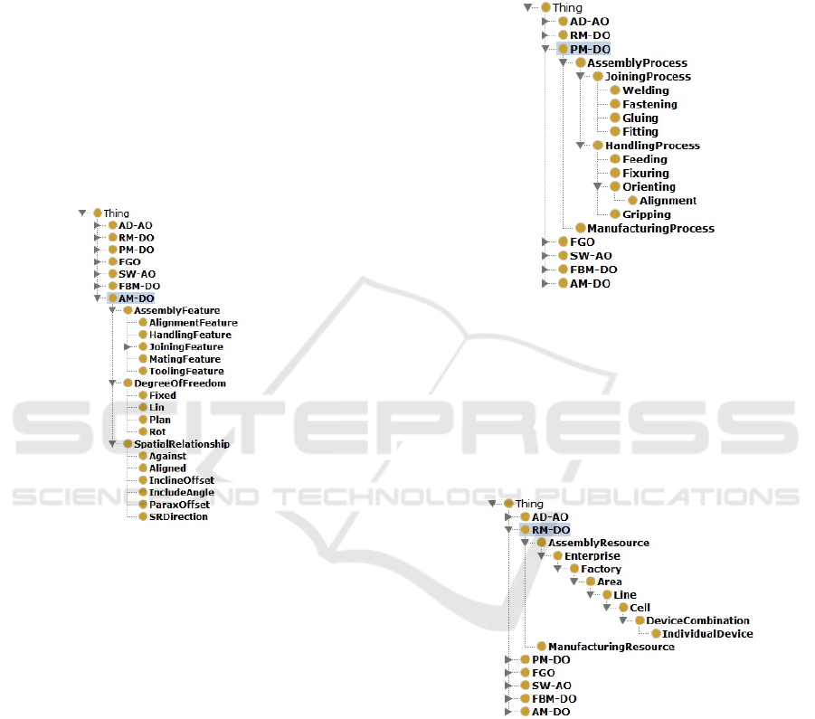
AM-DO is created for assembly modelling as
part of the product design domain (see Figure 9). If
KEOD 2016 - 8th International Conference on Knowledge Engineering and Ontology Development
108
the FBM-DO represents the form attribute
(geometrical and structural information) of the
product design, AM-DO represents the behaviour of
the design unit during assembly. AM-DO includes
three major subclasses: SpatialRelationship,
DegreeOfFreedom, and AssemblyFeature.
SpatialRelationship expresses the relative positions
of parts in an assembly in their final state.
DegreeOfFreedom is used to describe the motion
(translation and rotation) of parts during assembly.
The third subclass, AssemblyFeature, is composed
of Mating, Alignment, Handling, Joining, and
Tooling features. The AssemblyFeature class
introduces necessary assembly design information to
establish a link with assembly processes and
resources for APP.
Figure 9: The class hierarchy and concepts of the AM-DO.
Joining features, with further specializations
(welding features, fastening features etc.); represent
a link for integration with joining processes.
Handling and tooling features represent a link for
integration with assembly resources. Handling
features represent the geometrical characteristics of
the part that are needed to determine the required
assembly transporting resources such as fixture,
feeder, and gripper. Tooling features represent the
geometrical characteristics of the part’s shape that
are needed to determine the required assembly
tooling resources. An example of the tooling
features is the shape and size of the screw’s head,
which are required to determine the suitable tool.
The next two DSOs are the PM and the RM of
the APP domain. The PM-DO is illustrated in Figure
10, where the process class in GFO is expanded and
inherited by PM-DO into AssemblyProcess and
ManufacturingProcess classes. The
AssemblyProcess class is further expanded into
JoiningProcess and HandlingProcess classes. The
JoiningProcess class is composed of subclasses
representing different joining processes in APP such
as Welding and Fastening. The HandlingProcess
class is composed of Gripping, Feeding, and
Fixturing subclasses.
Figure 10: The class hierarchy and concepts of the PM-
DO.
The RM-DO represents manufacturing and
assembly resources in APP (Figure 11). The
AssemblyResource class is further decomposed into
several subclasses according to complexity from
Enterprise and Factory subclasses into Area, Line,
Cell, DeviceCombination, and IndividualDevice.
Figure 11: The class hierarchy and concepts of the RM-
DO.
The IndividualDevice subclass is further
inherited by AD-AO in the ASO layer, which will be
discussed in the next subsection.
3.3 Application Specific Ontology
(ASO)
So far, the ASO represents the lowest/ level of the
proposed ontology. ASO defines more specified,
Ontological Approach to Share Product Design Semantics for an Assembly
109
expanded and specialized concepts/properties for a
particular application. ASO is used to transfer
product data semantics between different
engineering applications. In this paper, two ASOs
are developed: SW-AO to share product design data
semantics from SolidWorks CAD software, and AD-
AO to utilize assembly processes and resources in
converting product data semantics into an assembly
process plan for performing assembly of a finished
or semi-finished product.
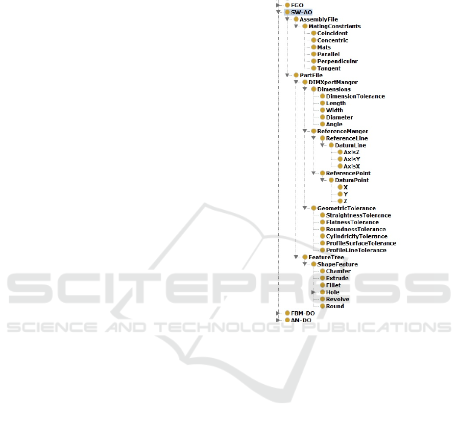
SolidWorks, as a commercial product design
package, has been widely used as a 3-D geometrical
modeler in various product life-cycle and product
development applications. SW-OA (Figure 12)
inherits and expands concepts from ontologies at
higher levels such as FormFeature from FBM-DO
and MatingFeature from AM-DO. For example,
FormFeature from FBM-DO inherits and expands
into Round, Revolve, Hole, Fillet, Extrude, and
Chamfer under ShapeFeature class in the SW-AO.
MatingFeature from AM-DO inherits into
Concentric, Tangent, Perpendicular, Parallel and
Coincident under AssemblyConstriants in the SW-
AO. SW-AO also defines unique concepts, which
are only used in SW. An example of the unique
classes in SW-AO is the DimXpertManger. This
class is composed of several subclasses such as
ReferenceManger, GeometricTolerance, and
Dimensions. The ReferenceManger subclass
determines positional parameters of the features.
Data for lines and points have been determined
under Datumline and DatumPoint, respectively. The
two subclasses GeometricTolerance and Dimensions
include all different types of dimensions and
tolerances, which have a direct impact on
geometrical variations in the assembly design.
The SD-AO (Figure 13) represents robotic
assembly device and consists of several units, which
are represented by subclasses:
HandlingAndOrientingTools, JoiningTools,
ToolChanger and Robot. The first two subclasses
include all different tools that will be used in
handling, orienting and joining parts during
assembly. The FixturingTool, GrippingTool and
FeedingTool are subclasses for the
HandlingAndOrienting class. Different types of
gripping tools as PincerGripper
, MagnetGripper,
VacuumGripper and FingerGripper under
GrippingTool subclass. Attributes and properties
could be defined for each gripper type such as
gripping range, gripping power and force.
JoiningTools includes WeldingTool, PressingTool,
and ScrewingTool. The Robot class includes
different robots that are commonly used in robotic
assembly devices such as ScaraRobot, MobileRobot,
and HexapodRobot.
Figure 12: Class hierarchy and concepts of the SW-AO.
The integration between product design domain
and APP will be performed through a mapping
procedure between SW-AO and SD-AO. The
processes and resources represented by different
tools in SD-AO will be selected according to the
product design semantics represented in SW-AO.
For example, a width dimension in Dimensions class
in SW-AO may determine the type of gripping
(whether it is finger gripping or magnet gripping) in
SD-AO. Another example is that a type of a hole in
ShapeFeature class in SW-AO might determine the
joining tool in SD-AO.
The ontology part in this paper will be expanded
in further work by defining axioms for the FDO and
properties for the DSOs and ASOs. Also a detailed
mapping procedure based on defined properties of
SW-AO and AD-AO has to be performed in the
future work.
KEOD 2016 - 8th International Conference on Knowledge Engineering and Ontology Development
110
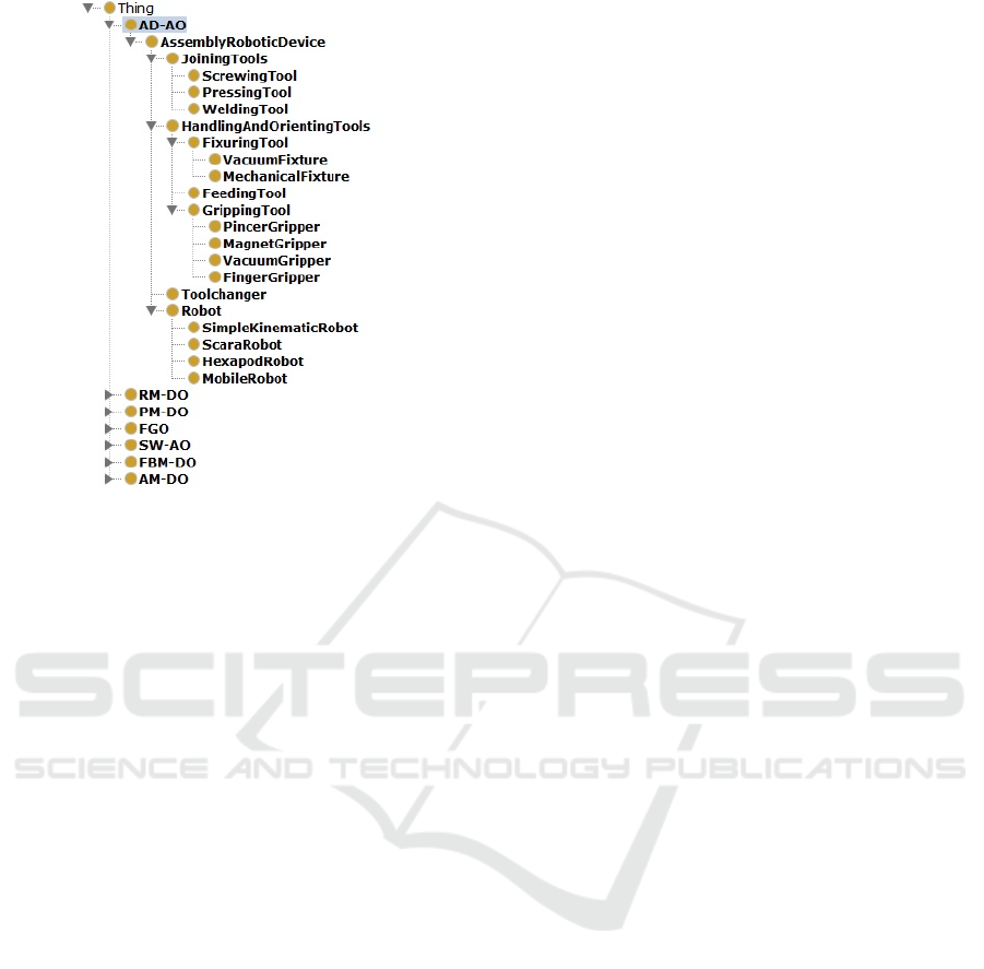
Figure 13: Class hierarchy and concepts of the SD-AO.
4 CONCLUSIONS
In this paper, a proposed approach for extracting and
integrating product design semantics to APP is
proposed. The proposed approach based on
extracting the related assembly design knowledge by
using SW-API, and on structure-layered ontology
for sharing and integrating product design semantics
with APP. Future work includes upgrading the
structure-layered ontology by developing the
ontological mapping procedure between assembly
design domain and APP.
REFERENCES
Delamer, I. M., & Lastra, J. L. 2006. Ontology modeling
of assembly processes and systems using Semantic
Web Services. International conference on industrial
informatics (pp. 611-617). IEEE.
Demoly, F., Matsokis, A., & Kiritsis, D. 2012. A
Mereotopological product relationship description
approach for assembly oriented design. Robotics and
Computer-Integrated Manufacturing, 28, 681–693.
Fikes, R., and Farquhar, A., 1999. Distributed
Repositories of Highly Expressive Reusable
Ontologies, IEEE Intelligent System, vol. 14, no. 2,
pp.73-79.
Gruber, T. R., 1993. Toward Principles of the Design of
Ontologies Used for Knowledge Sharing, International
Workshop on Formal Ontology in Conceptual
Analysis and Knowledge Representation.
Kim, K. 2003. Assembly operation tools for. Assembly
operation tools for e product design and realization.
PhD dissertation thesis. University of Pittsburgh.
Lanz, M., Garcia, F., Kallela, T., & T, R. 2008. Product-
process ontology for managing assembly specific
knowledge between product design and assembly
system simulation. In S. K. Svetan Ratchev, Micro-
Assembly.
Technologies and Applications (Vol. 260, pp. 99-108).
Boston: Springer.
Liu, Z. Y., Tan, J. R., Zhang, S. Y. and Jian, Z. F, 2000.
Design semantics of assembly modeling in virtual
environment: expression, transfer and transformation,
Chinese Journal of Computers, Vol. 23 No. 11, pp.
1208-14.
Lohse, N., Hirani, H., & Ratchev, S. 2006. Equipment
Ontology for modular reconfigurable assembly
systems. International journal of flexible
manufacturing system, 17, 301-314.
Miao, H. K., Sridharan, N., & Shah, J. J., 2002. CAD-
CAM integration using machining features.
International Journal of Computer Integrated
Manufacturing.
Mostefai, S., Bouras, A., & Batouche, M. 2006. Effective
collaboration in product development via a common
sharable ontology. International Journal of
Computational Intelligence, 206-212.
Patil, L., Dutta, D., and Sriram, R., 2005. Ontology-Based
Exchange of Product Data Semantics, IEEE
Transactions on Automation Science and Engineering,
vol. 2, no. 3, pp. 213-225.
Sanchez-Alonso, S., & Garcia-Barriocanal, E. 2006.
Making use of upper ontologies to foster
interoperability between SKOS concept schemes.
Online Information Review, 30(3), 253-277.
Shah, J. and Rogers, M. 1993. Assembly modeling as an
extension of feature-based design. Research in
Engineering Design, 5(3-4), pp.218-237.
Van Holland, W. 1997, Assembly features in modelling
and planning, PhD thesis, Delft University of
Technology.
Wierda, L., 1991. Linking Design, Process Planning and
Cost Information by Feature-based Modelling. Journal
of Engineering Design, 2(1), pp.3-19.
Wingard, L. 1991, Introducing Form Features in Product
Models, A step Towards CAD CAM with Engineering
Terminology, Licenciate Thesis, KTH: Royal Institute
of Technology.
Zhan, P., Jayaram, U., Jayaram, S., 2008. A Semantic
Approach for CAD/CAE Integration, Proceedings of
2008 NSF Engineering Research and Innovation
Conference.
Zhu, L. J., Jayaram, U., Jayaram, S., and Kim, O., 2009.
Ontology-Driven Integration of CAD/CAE
Applications: Strategies and Comparisons, ASME
IDETC/CIE Conference.
Ontological Approach to Share Product Design Semantics for an Assembly
111
