
A Portable, Inexpensive Point-Tracking System for Validation of
Wearable Biomechanics Sensors
G. P. Bailey and R. K. Harle
Computer Laboratory, University of Cambridge, William Gates Building, 15 JJ Thomson Avenue, Cambridge, U.K.
Keywords:
Stereo Vision, Ground Truth, Wearable Sensors, In-Field Assessment, Running, Gait, Foot Kinematics,
Continuous Sensing.
Abstract:
In-field validation of the accuracy of wearable sensors is desirable since algorithms that perform well in a
laboratory setting may not perform as well in real-world use. However, the use cases can be challenging. For
example, a foot worn wearable designed to measure foot trajectory should expect to be used in a variety of sce-
narios ranging from straightforward (running track) to challenging (a woodland area with many undulations).
Typically the more challenging the scenario the more difficult it is to get ground truth with conventional
systems. We describe a low-cost, highly-portable, point tracking system that can be used where space and
infrastructure is limited. The system is built around a pair of commodity video cameras in a stereo setup.
We demonstrate how to configure the cameras, a novel technique to approximate shutter synchronisation to
sub-frame interval, and we benchmark the system indoors against gold-standard motion capture systems. For
a runner 3 m from the cameras were able to recover their foot trajectory with a mean spatial deviation of
1.7±1.1 cm.
1 INTRODUCTION
Recent advances in wearable sensing have driven
an interest in in-situ measurement of athletic perfor-
mance. For the novice or amateur, wearable sen-
sors promise much, including automatic diagnosis of
faults in technique; motivation from quantitative per-
formance metrics available at every session; and sup-
port for rehabilitation when injured. There is value
even at the elite level—where detailed technique and
performance analysis is already commonplace—by
taking assessments out of the laboratory and into the
training or competition venue, moving them into the
background and making them more frequent.
A considerable challenge for the development of
these sensors is validation outside the laboratory. Our
motivation for this work is a foot-mounted inertial
sensor that is able to track the gait of runners to high
accuracy (Bailey and Harle, 2014a; Bailey and Harle,
2014b). The gold-standard measurement setups for
gait typically involve expensive 3D motion capture
systems such as Vicon. Unfortunately these systems
are bulky, hard to configure, only enable capture in a
small volume, and typically struggle outdoors, mak-
ing them laboratory-bound. Gait is therefore assessed
in the laboratory, with the athlete on a treadmill—
an approach we have previously used to evaluate our
wearable system (Bailey and Harle, 2014a; Bailey
and Harle, 2014b; Bailey and Harle, 2015).
However, the laboratory is often a poor simula-
tion of the real training environment. Treadmills limit
movement and force speeds, uneven terrain and gra-
dients are not considered, changes due to fatigue are
rarely captured due to short test durations, and the
athlete is acutely aware of being assessed, potentially
causing a change in behaviour. Because of these dif-
ferences, a successful evaluation of a system in the
laboratory does not necessarily imply the same—or
even similar—success will be achieved outdoors. Un-
fortunately it is all too easy for a system to produce an
erroneous but plausible result. This is not dissimilar
to the situation with general fitness trackers that base
activity levels on step counting. In the laboratory the
step counters are very accurate because the tests are
typically constrained and contrived. In the real world,
step counting errors of 20% or more have been regu-
larly reported. However, without a ground truth, users
of such systems just trust the number they are given
because it has a believable order of magnitude.
In this paper we describe the development and
evaluation of a low-cost, highly portable point track-
ing system—i.e. a system capable of recovering the
Bailey, G. and Harle, R.
A Por table, Inexpensive Point-Tracking System for Validation of Wearable Biomechanics Sensors.
DOI: 10.5220/0006082601150123
In Proceedings of the 4th International Congress on Sport Sciences Research and Technology Support (icSPORTS 2016), pages 115-123
ISBN: 978-989-758-205-9
Copyright
c
2016 by SCITEPRESS – Science and Technology Publications, Lda. All rights reserved
115
3D trajectory of a point within some defined volume.
Our system functions outdoors and and serves as a
valuable in-field ground truth for wearable sensors.
The system was designed to facilitate the evaluation
of our foot tracking inertial sensors, and we demon-
strate its value in this context.
2 BACKGROUND
Video systems are widely used in sports analysis as
they are easy to use and provide excellent qualitative
data. Quantitative data can be extracted from single
camera video systems by calibrating the video, how-
ever measurements must take place in a single plane
in which a calibration object is present. This can be
problematic for sports analysis as measurements may
not always occur within the correct plane—many ath-
lete motions are non-planar—leading to measurement
error. However, a calibrated stereo vision system is
able to estimate non-planar motions in 3D. The cam-
eras must be carefully calibrated to allow triangula-
tion of corresponding points in the two camera frames
(Zhang, 2002; Hartley and Zisserman, 2004; Heikkil
¨
a
and Silv
´
en, 1997). This research area is very mature
and robust stereo vision software is easily obtained:
Matlab’s Computer Vision Toolkit and OpenCV are
two popular choices.
Stereo vision is not without its issues, however.
Calibration is labour intensive, the capture volume is
relatively small (wide angle lenses allow for greater
capture volumes, at the cost of accuracy), and the two
cameras must be synchronised. The level of synchro-
nisation required depends on the desired positioning
accuracy and the expected speed of the object being
tracked. High-end systems typically synchronise to
milliseconds or better using a wired synchronisation
signal.
Parallel work in wearable sensors has aimed to
keep the portability of video systems while mitigating
its limitations. For example, investigation of inertial
sensors for foot tracking has been investigated previ-
ously for walking (Mariani et al., 2010; Sabatini et al.,
2005) and running (Bailey and Harle, 2014a; Bailey
and Harle, 2014b). We have previously proposed that
such systems should constitute an always-on, in-situ,
wearable system for gait assessment in runners. How-
ever, these systems have typically been evaluated in a
lab-based environment, either on a treadmill, or in a
contrived overground environment since the methods
of assessment are not easy to use in more challeng-
ing environments. However, there is a question as to
how such systems would perform in real world envi-
ronments. A previous study attempted to assess iner-
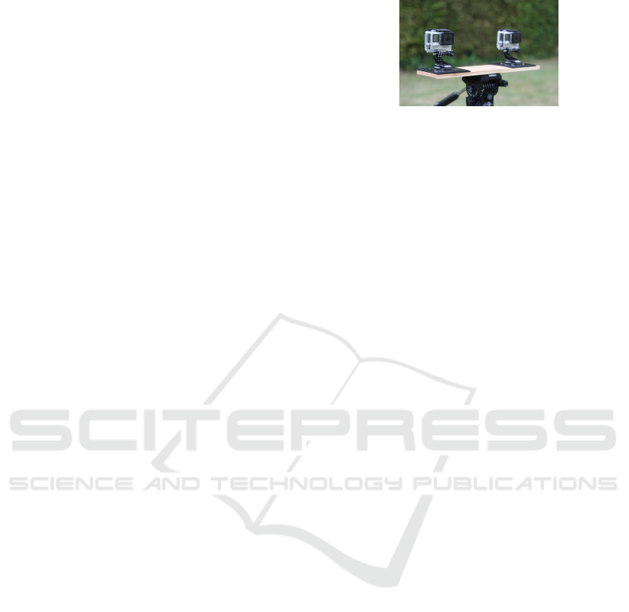
Figure 1: GoPro Hero4 cameras and jig. The distance
between the cameras is 0.25 m.
tial foot mounted trajectory recovery in a track en-
vironment (Bichler et al., 2012). The results were
poor for some spatial metrics. The reason for this
is unclear, although the authors suggest the particular
video reference system used was not robust or accu-
rate enough.
3 A LOW-COST PORTABLE
STEREO VISION GROUND
TRUTH
We sought to develop a lab-validated video reference
system to make ground truth measurements in real-
life scenarios. The requirements for our stereo vision
motion capture system were:
• a fast shutter speed (to minimise motion blur);
• a high frame rate (≥100 frames per second (fps)
to capture enough detail);
• a large depth of field (to prevent the need for con-
stant refocusing);
• a wide angle lens (to capture more of the run); and
• a small form factor that is robust and easily oper-
ated.
We use two GoPro Hero4 consumer cameras cap-
turing 1080p (1920×1080) video at 120 fps. We
mounted them to a custom rig as shown in Figure 1.
The mounting plates were fixed to the wooden plat-
form, giving an inter-camera spacing of 0.25 m.
A sample pair of images is provided in Figure 2.
The configuration allows capture of up to two typical
strides with the athlete approximately 3 m away. The
GoPro cameras use a wide angle lens to get this field
of view, which introduces significant radial distortion.
We account for this in the calibration step.
3.1 Camera Calibration
The system must be calibrated to establish both the
intrinsic camera parameters (e.g. focal length, distor-
tion, etc.) and the extrinsic parameters (camera posi-
tions and poses relative to each other). This is a key
icSPORTS 2016 - 4th International Congress on Sport Sciences Research and Technology Support
116
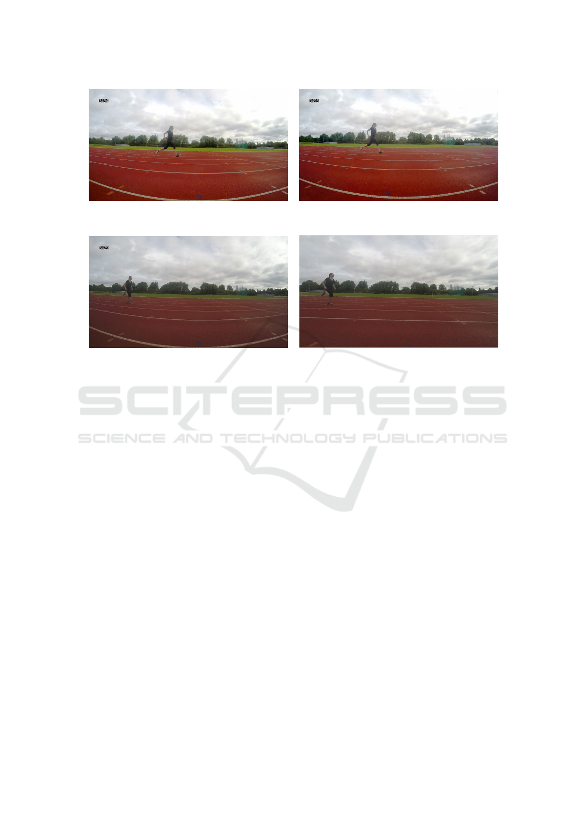
(a) Left (b) Right
Figure 2: A pair of sample frames from the stereo camera system.
(a) Original (b) Undistorted
Figure 3: An original frame with an undistorted frame.
problem in computer vision and we apply a standard
solution using a checkerboard pattern held at different
positions and orientations in the field of view of the
cameras. Once a sufficient number of images of the
checkerboard are captured, calibration algorithms can
be used to find the necessary parameters. Since we did
not require instantaneous trajectory feedback, we ran
the calibration software (Matlab’s Computer Vision
Toolkit, http://uk.mathworks.com/products/computer-
vision/) post-hoc.
To facilitate fast in-field calibration we recorded
continuously while the checkerboard was moved
around. We then extracted a series of stills to be used
for calibration. To avoid camera synchronisation er-
rors influencing the calibration (see section 3.3), the
checkerboard was held steady for a couple of seconds
at each position where a still was to be taken. Do-
ing so ensured that even a poor synchronisation (e.g.
out by multiple frames) will not adversely impact the
calibration.
Accurate estimation of the extrinsic parameters is
key to an accurate tracking result. However, the cam-
eras had to be removed from their housings to down-
load data. Therefore we took a new calibration se-
quence with each new measurement session.
Table 1 lists a typical calibration output and Fig-
ure 3 shows a captured image and its undistorted out-
put as an example. We note that the two cameras
feature similar intrinsic parameters, as expected for
mass-produced hardware. The estimated position of
camera 2 relative to camera 1 (247.6826±0.3813 mm)
closely matches our manually-measured 250 mm.
3.2 Determining Trajectory
Once the cameras are calibrated and synchronised
(see Section 3.3) images can be undistorted and
paired. The next step is to identify the 2D pixel co-
ordinates of the point(s) being tracked in each image
frame. If each point exhibits high contrast to its sur-
roundings (e.g. a brightly coloured sticker) this pro-
cess can be automated using standard computer vision
techniques. In this work we were tracking a single
point post-hoc so we preferred manual point identifi-
cation to avoid any error that may be introduced by
an algorithm. The final step is to triangulate the 3D
position of the point relative to (arbitrarily) camera 1.
We used the Matlab toolkit’s triangulate function
for this computation.
3.3 Camera Synchronisation
For successful output from a stereo vision system, it is
important to synchronise the two camera shutters, or
to know the period between the two shutters firing—
the shutter offset. Full shutter synchronisation is hard
A Portable, Inexpensive Point-Tracking System for Validation of Wearable Biomechanics Sensors
117

Table 1: Example calibration results.
(a) Intrinsic Parameters
Parameter Camera 1 Camera 2
Focal length (pixels) 897.24±3.56, 898.41±3.52 894.80±3.51, 895.24±3.49
Principal point (pixels) 991.14±3.79, 552.04±3.08 968.52±
0
3.82, 539.68±2.96
Skew 2.81±0.61 2.74±0.57
Radial distortion -0.265±0.0020,
0.099±0.002, -0.020±0.001
-0.268±0.002,
0.103±0.002, -0.022±0.001
Tangential distortion -0.0000±0.0003, -
0.0005±0.0002
-0.0000±0.0003, -
0.0002±0.0002
(b) Extrinsic Parameters (Relative to Camera 1)
Camera 2 Parameter Value
Rotation 0.0234±0.0004, -
0.0026±0.0009, -
0.0067±0.0001
Translation (mm) 247.68±0.38, -4.31±0.26, -
6.45±1.08
to achieve without a physical wire between cameras,
which is not available on the Hero4 (or almost any
consumer-grade camera). Wireless synchronisation is
offered on the Hero4 via its WiFi radio, but this is not
intended for accurate synchronisation—we observed
offsets of multiple frames in our tests. This is ac-
ceptable for the intended use—creating stereoscopic
video—since our visual systems cannot perceive a lag
of a few frames at 120 fps. For motion tracking, how-
ever, tighter synchronisation is necessary, as we show
here.
At 120 fps, the inter-frame period is a little over
8 ms. At its fastest point, a typical jogger’s foot will
move approximately 7 cm in this time. For a camera–
runner distance of approximately 3 m and a camera
separation of 0.25 m as we envisage here, the ge-
ometry of the angulation is not forgiving of such an
error—see Figure 4. If the foot is at point A when
the first (topmost) camera captures an image and at
point B (7 cm away from A) when the second camera
captures, the triangulation will predict a position at C.
This is 37 cm away from the true position in this ex-
ample. The observed difference will depend on where
in the frame the foot is, but errors of this magnitude
are not unexpected for the geometry we describe. If
we assume a maximum foot speed of 10 ms
−1
then
we need a synchronisation of
d
10
s to ensure the foot
does not move d m between frames. For d =5 mm
this requires synchronisation of 0.5 ms or better—
i.e. sub-frame synchronisation (or equivalently much
A
B
Plane
of foot
Figure 4: A scale drawing of the geometry for cameras
0.25 m apart and 3 m from the runner.
faster framerate) is necessary to give reliable depth
perception.
In order to estimate the shutter offset, we first as-
sume it to be constant—i.e. that the shutter clocks
do not drift significantly during an experiment. This
is a reasonable proposition for such short durations,
validated by the results we present in section 3.5.2.
Two challenges remain: to determine the shutter off-
set value; and to estimate the marker position at the
appropriate point between frames.
Addressing the latter first, we assume that the
movement between two consecutive frames can be
approximated by a straight line and we linearly inter-
polate the position from the measured positions of the
marker in the two frames in camera 2 that are either
side of the shutter event in camera 1.
To estimate the shutter offset, we have already
established that the 120 Hz sampling of the video
is insufficient. However, the 48 kHz audio streams
can be synchronised to tens of microseconds by
icSPORTS 2016 - 4th International Congress on Sport Sciences Research and Technology Support
118
cross-correlating the signal made by a synchronisa-
tion sound. Unfortunately, we found the synchro-
nisation between the video and audio streams is it-
self only approximate. This is common on mass-
market consumer cameras; the brain cannot perceive a
video/audio offset below approximately 20 ms. There
is thus little motivation to increase device complexity
and cost to achieve synchronisation better than 2–3
frames.
Our novel synchronisation technique is based on
the observation that a given erroneous shutter offset
will give larger depth estimates for faster moving ob-
jects for motion parallel to the camera sensor (‘hor-
izontal’ motion). i.e. the depth estimate is corre-
lated with the horizontal speed of the object when the
shutter offset is incorrect. When the shutter offset is
correct, we expect no correlation between horizontal
speed and depth estimate.
To exploit this we record an object accelerating
horizontally at approximately constant depth from the
camera. We use a simple pendulum, although any pla-
nar motion will do so long as it has sufficient velocity
and acceleration range, ideally incorporating a period
of zero velocity. We then consider a sequence of off-
set values from -0.5 f to +0.5 f increasing in units of
0.01 f , where f is the frame interval. For each we
compute the correlation coefficient between the speed
of the motion and the depth estimate. Note that the
true object speed is unobservable without the depth
information. However the ‘image speed‘ (in pixels
per second) is an acceptable surrogate since it is pro-
portional and thus exhibits the same correlation prop-
erties.
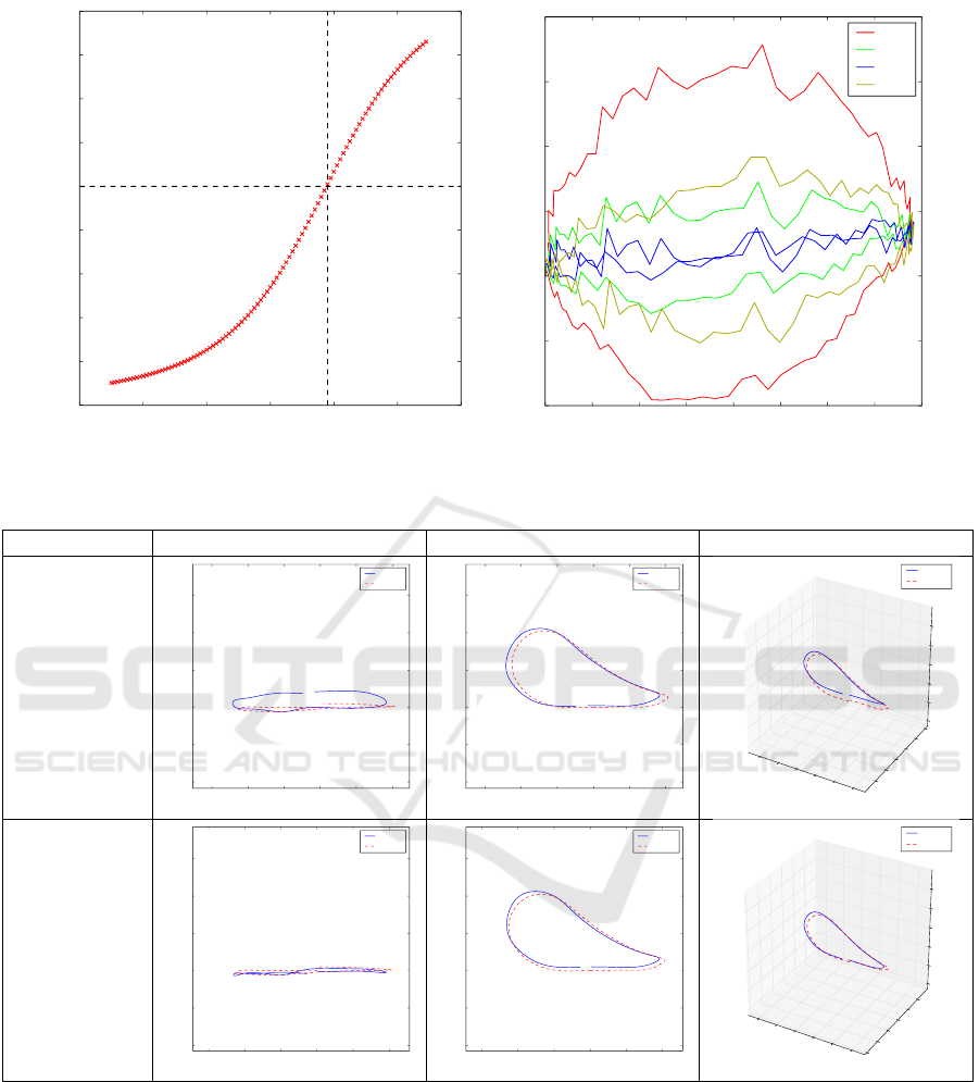
Figure 5(a) shows a typical progression of the cor-
relation coefficient as the shutter offset is changed.
The true offset is associated with zero correlation. In
the example shown, this corresponds to 0.18 f . Fig-
ure 5(b) shows a top-down view of the pendulum tra-
jectory for different offset values. Assuming the pen-
dulum moved only in the vertical plane parallel to the
camera sensor, we expect to see a straight line when
the offset is correct—we see that an offset of 0.18 f
did indeed produce the expected result. Note that all
offsets agree on the depth for the extremes of the mo-
tion: this reinforces the observation that the depth of a
stationary object (which the pendulum is at either ex-
treme) is independent of the shutter offset accuracy.
The full details of the shutter offset determination is
given in Algorithm 1.
As an aside we note that the pendulum is, in prin-
ciple, redundant when the runner passes the cam-
era rig parallel to the camera sensors. In this case
limbs will typically exhibit the necessary acceleration
range. In practice, we found many amateur runners
Algorithm 1: extract shutter offset.
input : video1, video from camera 1
input : video2, video from camera 2
output: Shutter offset in (fractional) frames
m
1
← extract marker path(video1)
m
2
← extract marker path(video2)
f ←
find sync to nearest frame(video1,video2)
v ← differentiate(low pass filter(m
1
))
o f f set ← -0.5
while (o f f set < 0.5) do
rs ← new array
m
0
2
← interpolate image coords(m
2
,
offset)
t ← extract 3d trajectory(m
1
,m
0
2
)
d ← low pass filter(depth(t))
r ← pearson coefficient(v,d)
rs.append(r)
offset ← offset + 0.01
return: f - 0.5 + 0.01×argmin(rs)
Table 2: Median trajectory errors for different step and shut-
ter offsets.
Step no.
Median error (cm)
Previous Nearest Interpolated Next
0 7.6 3.6 1.8 15.1
1 7.9 4.1 1.6 16.6
2 9.3 3.0 2.2 16.7
3 10.2 4.8 2.9 16.7
4 9.1 3.9 2.4 16.1
did not keep their limb motions planar and we had
more reliable results using an explicit synchronisation
process with the pendulum.
Figure 6 illustrates the importance of this syn-
chronisation scheme. It shows the raw trajectories
generated from the stereo vision system for a sample
step using nearest-frame synchronisation and interpo-
lated synchronisation. These steps were recorded in-
doors with Vicon ground truth (dashed red lines). We
see that the error was predominantly in the depth co-
ordinate. This is due to the camera being side-on to
the treadmill.
The interpolated result is also notably closer to
the ground truth. We quantitatively assess the error
by taking the median value of the distances between
corresponding points in the stereo vision and Vicon
trajectories. Table 2 shows the results for a series of
different steps, confirming that the interpolated offset
is at least as good as taking the nearest frame, and
usually significantly better.
A Portable, Inexpensive Point-Tracking System for Validation of Wearable Biomechanics Sensors
119
−0.6 −0.4 −0.2 0.0 0.2 0.4 0.6
Hypothetical Shutter Offset (Frames)
−1.0
−0.8
−0.6
−0.4
−0.2
0.0
0.2
0.4
0.6
0.8
Correlation Coefficient
(a) Correlation coefficient variation
0 200 400 600 800 1000 1200 1400 1600
x-coordinate (mm)
−100
−50
0
50
100
150
200
y-coordinate (mm)
-0.5
0
0.18
0.5
(b) Pendulum trajectory (top-down view)
Figure 5: Determining the shutter offset.
Sync point Top-down view Side-on view 3D view
Nearest frame
−600 −400 −200 0 200 400
X Coordinate (mm)
−400
−200
0
200
400
600
Y Coordinate (mm)
Stereo
Vicon
−600 −400 −200 0 200 400
X Coordinate (mm)
−400
−200
0
200
400
600
Y Coordinate (mm)
Stereo
Vicon
X Coordinate (mm)
−600
−400
−200
0
200
400
Y Coordinate (mm)
−400
−200
0
200
400
600
Z Coordinate (mm)
−400
−200
0
200
400
600
Stereo
Vicon
Interpolated
value
−600 −400 −200 0 200 400
X Coordinate (mm)
−400
−200
0
200
400
600
Y Coordinate (mm)
Stereo
Vicon
−600 −400 −200 0 200 400
X Coordinate (mm)
−400
−200
0
200
400
600
Y Coordinate (mm)
Stereo
Vicon
X Coordinate (mm)
−600
−400
−200
0
200
400
Y Coordinate (mm)
−600
−400
−200
0
200
400
Z Coordinate (mm)
−400
−200
0
200
400
600
Stereo
Vicon
Figure 6: Effect of synchronisation error for an example step (ground truth provided by Vicon).
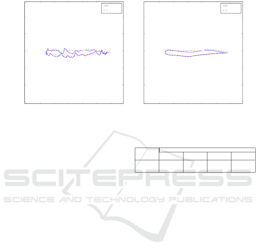
3.4 Trajectory Smoothing
The trajectory results in Figure 6 demonstrate that
even the interpolated synchronisation trajectory has
noise of a few centimetres in the depth axis. We ex-
pect smooth foot trajectories (as confirmed by the Vi-
con tracks) so we smooth the stereo vision trajectory.
We used a fourth order Butterworth low-pass filter
with a 10Hz cut-off frequency. This was found em-
pirically to give the best results (Figure 7).
3.5 Accuracy Evaluation
3.5.1 Method
To assess the accuracy of the stereo camera system,
we evaluated it in a lab-based environment. We used
a Vicon motion capture system to record the trajectory
icSPORTS 2016 - 4th International Congress on Sport Sciences Research and Technology Support
120
−800 −600 −400 −200 0 200 400
X Coordinate (mm)
−300
−200
−100
0
100
200
Y Coordinate (mm)
stereo
vicon
(a) Raw, unfiltered
−800 −600 −400 −200 0 200 400
X Coordinate (mm)
−300
−200
−100
0
100
200
Y Coordinate (mm)
stereo
vicon
(b) Low-Pass Filtered
Figure 7: Raw and smoothed stereo vision trajectories vs Vicon ground truth (top-down view). (Depth (y − axis) exaggerated
for visibility).
of a marker attached to a treadmill runner’s shoe. We
selected a treadmill speed of (3.4 ms
−1
, a typical run-
ning pace). The stereo vision system was used to track
the same marker across five steps in each trial. As
before a treadmill–camera distance of approximately
3 m was used.
Three runners were recruited and each performed
three runs on the treadmill: one where they were in
the centre of the vision system’s frame; one to the left;
and one to the right (see Figure 8). This resulted in
three trials of five steps for three camera angles, and a
total of over 3800 3D points for evaluation. To com-
pare the Vicon and vision trajectories, we manually
aligned the two co-ordinate systems and looked at the
co-ordinate errors.
3.5.2 Accuracy Results and Discussion
Table 3 gives the mean and standard deviation of
the errors observed between the Vicon and vision
trajectories. We found a 3D euclidean error of ap-
proximately 2±1 cm. The errors at the edge of the
camera frame (where lens distortion is strongest) are
marginally greater but surprisingly similar.
These errors might be expected to improve out-
doors, where the higher ambient light level permits
a faster shutter speed (the GoPro cameras adapt the
shutter speed automatically). Faster shutter speeds
correspond to reduced motion blur and thus more ac-
curate pixel co-ordinates of markers. Nonetheless, ac-
curacies around 2 cm are of value to verify the op-
eration of in-situ sensors, especially given the higher
portability and significantly reduced cost compared to
motion capture systems.
Table 3: Laboratory trajectory errors.
Aspect
Mean error ± Standard deviation (cm)
x-axis y-axis z-axis
3D error
magnitude
Left -0.0±0.8 -0.0±1.1 -0.1±1.6 1.8±1.1
Centre -0.4±0.7 -0.3±1.1 0.3±1.4 1.7±1.1
Right -0.1±0.8 -0.6±1.2 0.3±2.0 2.1±1.4
4 COMPARISON WITH
INERTIAL SENSORS
We have previously used foot mounted inertial sen-
sors to extract spatial (Bailey and Harle, 2014a; Bai-
ley and Harle, 2014b) and temporal (Bailey and Harle,
2015) measurements of running gait. This involves
integrating gyroscope and accelerometer data to form
a strapdown Inertial Navigation System (INS). These
systems require drift to be accounted and corrected
for, using de-drifting techniques (Mariani et al., 2010;
Bailey and Harle, 2014a), a Kalman Filter (Foxlin,
2005; Bailey and Harle, 2014a) or similar.
We ran a pilot study to compare our inertial results
to the stereo vision system. We collected 10 running
trials. During each trial the participant ran through
the camera field of view allowing capture of a single
stride with the vision system. The videos were post-
processed to extract 3D foot trajectory by identifying
a coloured marker attached to the shoe and co-located
with the inertial sensor.
The inertial sensor was a modified Shim-
mer Shimmer3 Inertial Measurement Unit
(IMU,www.shimmersensing.com). We added a
200g accelerometer to the package following the dis-
A Portable, Inexpensive Point-Tracking System for Validation of Wearable Biomechanics Sensors
121
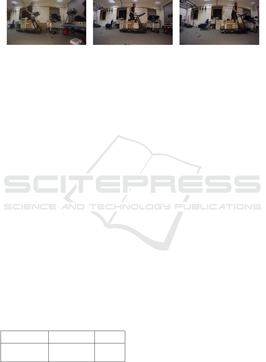
(a) Left Frame (b) Centre Frame (c) Right Frame
Figure 8: Field of view coverage of the three camera angles tested.
covery that the integrated 16g sensor sensor saturates
during a typical running stride (Bailey and Harle,
2014b). We generate individual step trajectories
from the inertial data using a de-drifted strapdown
algorithm (Mariani et al., 2010; Bailey and Harle,
2014a).
After processing we had 10 overground running
steps at a mean running speed of 5.4ms
−1
that were
captured by both the stereo vision and inertial subsys-
tems.
4.1 Results
The inertial system estimates both the foot position
and attitude of the foot during each stride, while the
stereo vision system is limited to foot position. Since
we have verified both the trajectory and attitude es-
timates in the laboratory, we focus on evaluating the
trajectory under the assumption that a good trajectory
estimate implies correct attitude.
We used spatial metrics to assess agreement be-
tween the two systems. Foot clearance, mean step
velocity and stride length were chosen as commonly
used statistics for gait assessment (Mariani et al.,
2010; Bailey and Harle, 2014a). The results in Ta-
ble 4 show strong correlation coefficients from mea-
surements taken from each system implying that the
stereo vision system is working well and that the algo-
rithms used in treadmill running work as expected for
basic overground running on flat ground. This clearly
does not constitute a full evaluation of the inertial de-
rived metrics, but serves to show the stereo system can
plausibly be used for such a purpose. The full evalua-
tion falls outside of the scope of this paper and is left
as future work.
Table 4: Mean and Standard Deviation of Error.
Measurement Error Correlation
Coefficient
Mean Step Velocity −0.28 ± 0.07ms
−1
0.99
Stride Length −0.1 ± 5.2cm 0.96
Foot Clearance −4.2 ± 2.1cm 0.87
5 CONCLUSIONS AND FURTHER
WORK
We have shown that off-the-shelf commodity video
hardware can be used to track a point using a stereo
camera setup with centimetre level accuracy. This is
difficult due to the issue of synchronisation between
cameras, but our novel approach to camera synchro-
nisation makes it possible to use such a set up for
athletic activities despite the faster motion inherent in
these scenarios. We have used the system to assess
foot kinematics in overground running and compared
them to a previously evaluated wearable system dur-
ing a small pilot study. Further work should use this
system to fully evaluate the ability of foot mounted
inertial sensors to assess spatial metrics in challeng-
ing environments including on slopes or undulating
ground.
ACKNOWLEDGEMENTS
This work was funded by Qualcomm Inc. In addition
to financial support the authors would like to recog-
nise the technical contributions of the Advanced Lo-
cation Algorithms group at Qualcomm Cambridge.
REFERENCES
Bailey, G. P. and Harle, R. (2014a). Assessment of foot
kinematics during steady state running using a foot-
mounted IMU. In Procedia Engineering , volume 72,
pages 32–37.
Bailey, G. P. and Harle, R. K. (2014b). Investigation of Sen-
sor Parameters for Kinematic Assessment of Steady
State Running Using Foot Mounted IMUs. In Pro-
ceedings of the 2nd International Congress on Sports
Sciences Research and Technology Support, pages
154–161. SCITEPRESS - Science and and Technol-
ogy Publications.
Bailey, G. P. and Harle, R. K. (2015). Measuring Tempo-
ral Parameters of Gait with Foot Mounted IMUs in
icSPORTS 2016 - 4th International Congress on Sport Sciences Research and Technology Support
122

Steady State Running. In Proceedings of the 3rd In-
ternational Congress on Sport Sciences Research and
Technology Support, number icSPORTS, pages 24–
33. SCITEPRESS - Science and and Technology Pub-
lications.
Bichler, S., Ogris, G., Kremser, V., Schwab, F., Knott,
S., and Baca, A. (2012). Towards high-precision
IMU/GPS-based stride-parameter determination in an
outdoor runners’ scenario. In Procedia Engineering,
volume 34, pages 592–597.
Foxlin, E. (2005). Pedestrian tracking with shoe-mounted
inertial sensors. IEEE Computer Graphics and Appli-
cations, 25(6):38–46.
Hartley, R. I. and Zisserman, A. (2004). Multiple View Ge-
ometry in Computer Vision. Cambridge University
Press, ISBN: 0521540518, second edition.
Heikkil
¨
a, J. and Silv
´
en, O. (1997). A Four-step Camera
Calibration Procedure with Implicit Image Correction.
Cvpr, pages 1106–1112.
Mariani, B., Hoskovec, C., Rochat, S., B
¨
ula, C., Penders, J.,
and Aminian, K. (2010). 3D gait assessment in young
and elderly subjects using foot-worn inertial sensors.
Journal of Biomechanics, 43:2999–3006.
Sabatini, A. M., Martelloni, C., Scapellato, S., and Cav-
allo, F. (2005). Assessment of walking features from
foot inertial sensing. IEEE Transactions on Biomedi-
cal Engineering, 52:486–494.
Zhang, Z. (2002). A Flexible New Technique for Cam-
era Calibration (Technical Report). IEEE Transac-
tions on Pattern Analysis and Machine Intelligence,
22(11):1330–1334.
A Portable, Inexpensive Point-Tracking System for Validation of Wearable Biomechanics Sensors
123
