
A Framework for Process Driven Software Configuration
Andreas Daniel Sinnhofer
1
, Peter P
¨
uhringer, Klaus Potzmader
2
, Clemens Orthacker
2
,
Christian Steger
1
and Christian Kreiner
1
1
Institute of Technical Informatics, Graz University of Technology, Graz, Austria
2
NXP Semiconductors, Gratkorn, Austria
{a.sinnhofer, christian.kreiner, steger}@tugraz.at, p.puehringer@inode.at, {klaus.potzmader, clemens.orthacker}@nxp.com
Keywords:
Software Product Lines, Feature Oriented Modelling, Business Processes, Tool Configuration.
Abstract:
Business processes have proven to be essential for organisations to be highly flexible and competitive in
today’s markets. However, good process management is not enough to survive in a market if the according
IT landscape is not aligned to the business processes. Especially industries focused on software products are
facing big problems if the according processes are not aligned to the overall software system architecture.
Often, a lot of development resources are spent for features which are never addressed by any business goals,
leading to unnecessary development costs. In this paper, a framework for a business process driven software
product line configuration will be presented, to provide a systematic way to configure software toolchains.
1 INTRODUCTION
Business Process (BP) oriented organisations are
known to perform better regarding highly flexible
demands of the market and fast production cycles
(e.g. McCormack and Johnson (2000); Valena et al.
(2013); Willaert et al. (2007)). This is achieved
through the introduction of a management process,
where business processes are modelled, analysed and
optimised in iterative ways. Nowadays, business pro-
cess management is also coupled with a workflow
management, providing the ability to integrate the re-
sponsible participants into the process and to moni-
tor the correct execution of it in each process step.
To administer the rising requirements, so called busi-
ness process management tools are used (BPM-Tools)
which cover process modelling, optimization and exe-
cution. In combination with an Enterprise-Resource-
Planning (ERP) system, the data of the real process
can be integrated into the management process.
In the domain of software products, different
choices in business processes lead to different soft-
ware configurations. To handle variability automat-
ically is a challenging task because the variability of
the process model needs to be reflected in the software
architecture. Further, the actual customer choice dur-
ing the ordering process needs to be mapped to the ac-
cording software features. Due to this, software con-
figuration is often done manually which takes a con-
siderable amount of time during production. Partic-
ularly for resource constraint devices like embedded
systems, it is vital to have a working software configu-
ration process since unnecessary features may occupy
a lot of memory. Further, it is important to have a
software architecture which is synchronised with the
business goals. Otherwise, a lot of resources are spent
for developing and maintaining software components
which are never used anyway. Thus, process aware-
ness is crucial for an efficient development.
Context Aware Business Process modelling is a
technique for businesses living in a complex and
dynamic environment (Saidani and Nurcan (2007)).
In such an environment a company needs to tackle
changing requirements which are dependent on the
context of the system. Such context sensitive busi-
ness process models are able to adapt the execution of
their process instances according to the needs, such
that the company can react faster and more flexible.
This is achieved by analysing the context states of
the environment and mapping these states to the ac-
cording business processes and their related software
system. The problem with such approaches is, that
the used software systems are often developed in-
dependently from each other, although they share a
similar software architecture. Therefore, this work
focuses on the development of a framework which
covers the variability of process models and mapping
such variable process structures to software configu-
ration artefacts such that the software system can be
adapted automatically with respect to its context. This
196
Daniel Sinnhofer A., PÃijhringer P., Potzmader K., Orthacker C., Steger C. and Kreiner C.
A Framework for Process Driven Software Configuration.
DOI: 10.5220/0006223701960203
In Proceedings of the Sixth International Symposium on Business Modeling and Software Design (BMSD 2016), pages 196-203
ISBN: 978-989-758-190-8
Copyright
c
2016 by SCITEPRESS – Science and Technology Publications, Lda. All rights reserved
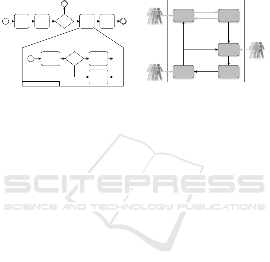
Quotation
Handling
Approve
Order
Approved?
Order
Handling
Yes
No
Payment
Customer
Requirements
In House?
Procure
Contractors
No
Schedule /
assign work
Yes
...
...
Sub-Process: Order Handling
Figure 1: Exemplary order process to illustrate the basic
concepts defined by
¨
Osterle (1995): A high level descrip-
tion of the process is split into its sub-processes until a com-
plete work description is reached.
is achieved through software product line engineering
techniques. Thus, only one system needs to be devel-
oped and maintained for whole product families. The
modelling of business process variability is based on
our previous work, which can be found in Sinnhofer
et al. (2015). In particular, a SPLE Tool was used
to systematically reuse expert knowledge in form of
valid process variations, designed in an appropriated
BPM Tool. The integrity of the process variations is
secured by the capabilities of the BPM Tool and a
rich cross functional constraint checking in the SPLE
Tool. This work will extend the framework in order to
be able to map process artefacts to software configu-
rations. Hence, software toolchains can be configured
in an automatic way and the architecture can be kept
aligned with the business goals.
This work is structured in the following way:
Section 2 gives an overview over the used design
paradigm for business processes modelling and Soft-
ware Product Line Engineering techniques which
were needed for the framework. Section 3 summa-
rizes the concept of our work and Section 4 describes
our implementation in an industrial use case. Finally,
Section 5 summarizes the related work and Section 6
concludes this work and gives an overview over future
work.
2 BACKGROUND
2.1 Business Processes
A business process can be seen as a sequence of
tasks/sub-processes which need to be executed in a
specific way to produce a specific output with value
to the costumer (Hammer and Champy (1993)). Ac-
BPM-Tool SPLE-Tool
Business
Processes
Feature Model
Derive /
Update
Feature
Selection
TransformationProcess Variant
Maintenance
/ Evolution
Process Designer
Production Experts
Production Experts
Derive
Update
Figure 2: Used framework for an automatic business pro-
cess variant generation (adapted from Sinnhofer et al.
(2015)). The grey lines indicate process steps which need
to be done manually.
cording to
¨
Osterle (1995) the process design on a
macroscopic level (high degree of abstraction) is split
up into sub-processes until the microscopic level is
reached. This is achieved, when all tasks are detailed
enough, so that they can be used as work instructions.
An exemplary order process is illustrated in Figure 1.
As illustrated, the top layer is a highly abstracted de-
scription, while the production steps are further re-
fined on the lower levels. As a result, the lowest
level is highly dependable on the concrete product and
production environment, providing many details for
the employees. Usually, the top layers are indepen-
dent from the concrete plant and the supply chain and
could be interchanged throughout production plants.
Only the lower levels (the refinements) would need to
be reconsidered. Variability of such a process struc-
ture can either be expressed through a variable struc-
ture of a process/sub-process (e.g. adding/removing
nodes in a sequence) or by replacing the process re-
finement with different processes.
Traditionally, processes for similar products are
created using a copy and clone strategy. As a result,
maintaining such similar processes is a time consum-
ing task, since every improvement needs to be propa-
gated manually to the respective processes. To solve
this issue, we proposed a framework to automatically
derive process variants from business process mod-
els by modelling the variable parts of a process us-
ing Software Product Line Engineering techniques in
a previous work (see Sinnhofer et al. (2015)). The
presented framework can be split into four different
phases which are illustrated in Figure 2. In the first
phase, process designers create process templates in a
BPM tool, adding all wished features like documen-
tation artefacts, responsible workers or resources. In
the second phase, the created processes are imported
into the SPLE tool and added to a feature model. Pro-
A Framework for Process Driven Software Configuration
197
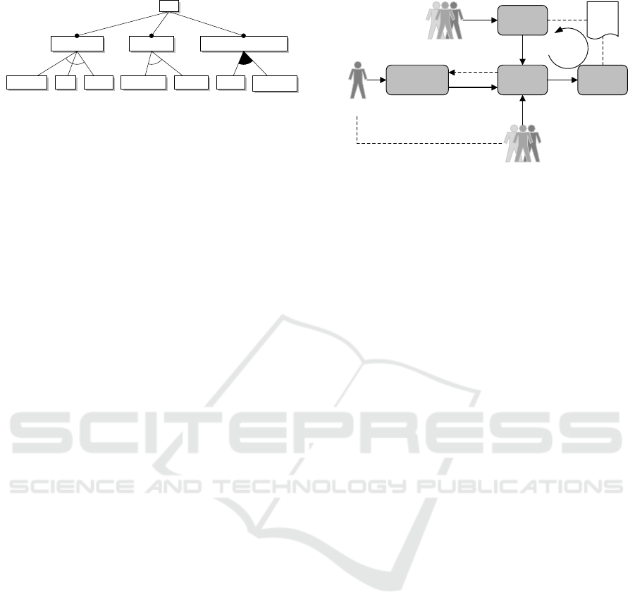
car
Engine Type Gear Type Entertainment System
Electrical Gas Diesel Automatic Manual Radio CD-Player
Figure 3: An exemplary feature model of a car.
cess experts define a comprehensive set of rules and
restrictions so that only valid process variants can be
derived from the model. The third phase is called the
feature selection phase in which production experts
will automatically derive processes for their needs
based on a selection of features. The fourth phase
consists of maintenance and evolution. There, data
is collected and used to improve process designs or
feature selections.
2.2 Software Product Line Engineering
SPLE applies the concepts of product lines to soft-
ware products (Kang et al. (1990)). A Software
Product Line can be seen as a set of domain fea-
tures, which are automatically assembled and con-
figured to a whole software project just by choosing
the wanted features. Instead of writing code for a
whole system, the developer divides the project into
small lightweight features which are implemented in
so called domain artefacts. For this, a software ar-
chitecture is needed in which the variation points and
the respective variants (features) are explicitly mod-
elled. Further, a source code generator is needed
which is able to generate the according software prod-
ucts, based on the according feature selection.
Features are usually modelled in so called ’Fea-
ture Models’ which describe all features of a product
and explicitly states their relationships, dependencies
and additional restrictions between each other. Fig-
ure 3 illustrates an explanatory feature model for a
car. A car consists of three mandatory variation points
(Engine Type, Gear Type, Entertainment System) and
their respective variants. For example, the Engine
Type of the car could be Electrical, Gas or Diesel
powered. The variants of the ’Engine Type’ and ’Gear
Type’ variation point are modelled as alternative fea-
tures which means that exactly one variant needs to
be chosen. In contrast, the ’Entertainment System’ is
modelled in such a way, that either one or both options
can be chosen.
3 VARIABILITY FRAMEWORK
The goal of the developed framework is to implement
Order Entry
(e.g. Web-Interface)
Process
Variability
Framework
Customer
Domain Experts
Process Variant
Process
Model
Execute Process
Internal Customer
generated
configures
configures
Maintenance
Evolve
influences
Figure 4: Overall conceptual design of the framework. The
”Process Variability Framework” block is described in Fig-
ure 2.
a systematic way to keep the business processes
aligned with the IT infrastructure so that development
costs can be reduced and the company is more flexi-
ble to changes of the market. The following Sections
summarizes our developed framework.
3.1 Conceptual Design
The overall conceptual design is based on a feature
oriented domain modelling framework and is dis-
played in Figure 4. As illustrated in the Figure, Do-
main Experts are responsible for operating the ”Pro-
cess Variability Framework” as already described in
Section 2.1. They design process models based on
their domain knowledge and generate process vari-
ants for various types of product platforms. Based
on this variants, the used SPLE tool also generates a
order entry form, stating explicitly which kind of in-
formation a customer needs to submit, to be able to
order the product. For example, if the customer can
decide which applications should run on his device
or if the device can be personalized by adding signa-
tures of the customer. Complex products usually tend
to have a lot of internal stackholders which can be
seen as internal customers. This means that based on
the customer needs, specific stackholders may be ad-
dressed to further submit needed information or even
parts of the product. For instance, if a product can run
on multiple hardware platforms, each of these plat-
forms may be developed by different departments or
even different companies which need to be ordered
and shipped accordingly. To be able to automatically
generate the order entry forms, additional information
needs to be added to the process models. This can be
done by either adding this information into the pro-
cess model itself (i.e. using the BPM tool) or by us-
ing the capabilities of the SPLE tool and mapping this
information to the according process models. Option
two is the more generic approach which also has the
Sixth International Symposium on Business Modeling and Software Design
198

positive side-effect, that the processes itself are not
”polluted” with information that may change in dif-
ferent circumstances. On the other hand, it rises high
requirements to the SPLE tool which needs to sup-
port product family models so that the process model
and the additional information used for the order en-
try can be kept aligned, but separated which increases
the reusability factor.
After all needed data is collected, the process can
finally be executed and the ordered products are man-
ufactured. Especially for new products, it is likely
that during this manufacturing process knowledge is
gained on how to increase the efficiency of the whole
process(es) by introducing specific changes to the
process model. Further, changes to the generated or-
der entry may be identified, which means that specific
parts of the product need to be made selectable. The
advantage of using one core of process models for a
specific family of products is that the gained knowl-
edge can be rolled out in an automatic way for the
whole product family. This means that the required
changes only need to be implemented once.
3.2 Type Model
To automatically generate order entry forms from a
feature selection, the used model needs to support the
following types:
• Inputs: Is the abstract concept of different Input
types which are described below.
• None: No special data needs to be submitted and
hence a node (i.e. task in a process) marked with
none will not appear as a setting in the order entry
form.
• Customer Input: Specific data need to be added
from a customer. A node marked with this will
generate an entry in the order entry form of a spe-
cific type. For example a file upload button will
appear if a customer needs to submit specific files.
• Internal Input: Specific data or parts of the prod-
uct needs to be delivered from an internal stack-
holder. This information is directly submitted to
the internal stackholder as a separate order.
Furthermore, the family model should support the
concept of choices (i.e. a customer needs to submit
one of possible n options) and multiple inputs if mul-
tiple submissions are needed for a single node. Also
multiple inputs of multiple different stackholder need
to be supported.
3.3 Process Driven Software Toolchain
Configuration
An established process management, which is able to
generate order entry forms and trigger internal pro-
cesses, is a big step towards good business manage-
ment. However, to be successful on the market it is
not enough to just focus on well managed processes,
but also on an aligned IT infrastructure. Hence, the
big remaining challenge is having an IT infrastruc-
ture which is able to be configured directly from the
according business processes.
For illustration purposes let’s consider the follow-
ing example: A company is developing small embed-
ded systems which are used as sensing devices for the
internet of things. The device is offered in three dif-
ferent variants with the following features:
• Version 1: Senses the data in a given time inter-
val and sends the recorder signal to a web-server
which is used for post-processing.
• Version 2: Additionally to the features of
Version 1, this version allows encryption of the
sensed data using symmetric cryptography before
it is sent to the web-server. This prevents that third
parties are able to read the data. For simplicity, we
assume that this key is provided in plain from the
customer.
• Version 3: Additionally to the features of
Version 2, this version also allows customer ap-
plications to be run (e.g. data pre-processing rou-
tines) on the system.
It is not economic feasible to personalize each de-
vice manually if it is sold in high quantities. Fur-
ther, establishing three different order processes using
three different versions of customization toolchains
will result in higher maintenance efforts. To summa-
rize the findings of this short example, it is fundamen-
tal to have a software architecture which is synchro-
nized with the according business process(es). This
means that variable parts of the process model need to
be reflected by a variable software architecture. Fur-
ther, minor changes to the process model (e.g. addi-
tion of new configuration settings) should not lead to
huge development efforts since – ideally – the soft-
ware architecture does not need to be changed. These
requirements lead to the architecture displayed in Fig-
ure 5. As illustrated, the tool is basically an interpreter
which can be ”dynamically programmed” for the ac-
tual order. This means that variability of the archi-
tecture is gained by shifting features from the imple-
mentation phase to the configuration phase. To en-
sure that such freedom is not misused, it is necessary
to enforce specific rules in the Interpreter Tool (e.g.
A Framework for Process Driven Software Configuration
199
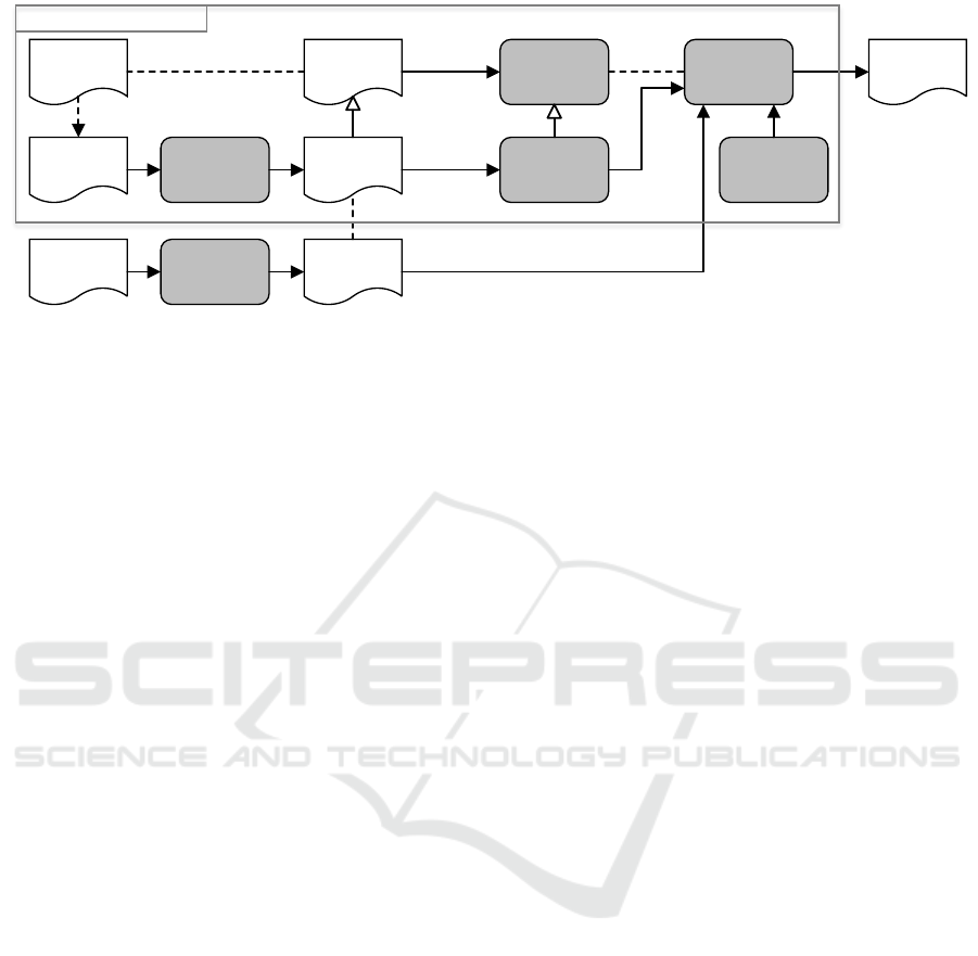
Process
Model
Abstract Class
Hierarchy
Generate
Implementation
Instantiate
XSD Schema
XMLOrder Entry
Converter
Interpreter Tool
Output
Restrictions
Customer
Submissions
Converter
XML
Product Configuration
Defined per Product Family
Figure 5: The architecture of the software tool responsible for generating the wished product outcome.
security requirements). Based on the Process Model
of the Process Variability Framework, a schema file
is created which states all possible operations and all
additional language primitives (like conditional state-
ments, etc.) the Interpreter Tool can perform. This
step is semi-automatic which means that only a skele-
ton of the needed functionality can be generated auto-
matically.
For illustration purposes we will reconsider the
previous example: Basically, there are three different
order processes, where in the first case a customer can
customize a connection string for his web-server. In
the second case he can further submit a key which is
stored onto the nodes and in the third case executables
can be submitted to be loaded to the chip. Taking this
into account, the XML illustrated in Listing 1 can be
generated. Each function consists of a Configuration
block and a Translate block. The Configuration block
is used to indicate which data needs to be provided
from the customer submissions (i.e. from the ”real”
Listing 1: Generated XML based on the Order Entry. The
Translate blocks need to be edited manually by a developer.
1 <?xml v e rs i on =” 1 .0 ” en co di n g = ”UTF−8” ?>
2 <F u n c t i o n s>
3 <Fu n c t io n id =” W eb Se rv er ”
4 minOccurs= ” 1 ”
5 maxOccurs=” 1 ”>
6 <C o n f ig u r a t i o n>
7 <Param ete r name= ” C o n n e c t i o n ” t y p e =” i p A d d r e s s ” />
8 </ C o n f i gu r a t i o n>
9 <T r a n s l a t e> . . . </ T r a n s l a t e>
10 </ F u n cti o n>
11 <Fu n c t io n id =” En cr yp ti on Ke y ”
12 minOccurs= ” 0 ”
13 maxOccurs=” 1 ”>
14 <C o n f ig u r a t i o n>
15 <Param ete r name= ”Key” ty p e =” h e x s t r i n g ” />
16 </ C o n f i gu r a t i o n>
17 <T r a n s l a t e> . . . </ T r a n s l a t e>
18 </ F u n cti o n>
19 <Fu n c t io n id =” I n s t a l l A p p l i c a t i o n ”
20 minOccurs= ” 0 ”
21 maxOccurs=” u nb ou n de d ”>
22 <C o n f ig u r a t i o n>
23 <Param ete r name= ” B in a r y ” t y p e =” f i l e U r i ” />
24 <C o n f ig u r a t i o n>
25 <T r a n s l a t e> . . . </ T r a n s l a t e>
26 </ F u n cti o n>
27 </ F u n c t i o n s>
product configuration) and how often they can occur
(configuration safety). This Configuration blocks are
further used to generate a schema file which is used
by the converter tool to convert the Customer Submis-
sions into the needed XML structure. The Translate
block defines how the submitted data is processed.
This cannot be generated and hence a developer is
needed who needs to define this transformation based
on the language primitives of the Interpreter Tool.
This needs to be done only once for a whole product
family. For this particular example, only a Store-Data
and an Install-Application routine would need to be
offered by the interpreter. Additional restrictions are
domain depended and could contain in that example
the following checks: Verification that the submitted
key is of reasonable strength (e.g. AES key with a
minimum length of 16 bit) and that the submitted ap-
plications are protected by a signature of the customer
to ensure that they are not replaced by a malicious
third party. If a product is ordered, the filled order
entry (i.e. customer submissions) is converted into a
Listing 2: Exemplary generated Configuration file based on
customer submissions. Two different versions are shown.
The first example illustrates a ”Version 3” product and the
second one a ”Version 1” product.
1 <?xml v e r s i o n = ” 1 . 0 ” en c o di n g = ”UTF−8” ?>
2 <CustomerOrder>
3 <WebServer>
4 <Co nn e ct i o n>X . X . X . X</ C on n ec t i on>
5 </ WebServer>
6 <Enc ry pt io nKe y>
7 <Key>0 x0 10 20 30 4 . . .<Key>
8 </ Enc ry pt io nK ey>
9 <I n s t a l l A p p l i c a t i o n>
10 <Bin ar y> f i l e : / / orderXYZ / app1 . e l f</ Bi n ar y>
11 </ I n s t a l l A p p l i c a t i o n>
12 <I n s t a l l A p p l i c a t i o n>
13 <Bin ar y> f i l e : / / orderXYZ / app2 . e l f</ Bi n ar y>
14 </ I n s t a l l A p p l i c a t i o n>
15 </ CustomerOrder>
1 <?xml v e r s i o n = ” 1 . 0 ” en c o di n g = ”UTF−8” ?>
2 <CustomerOrder>
3 <WebServer>
4 <Co nn e ct i o n>X . X . X . X</ C on n ec t i on>
5 </ WebServer>
6 </ CustomerOrder>
Sixth International Symposium on Business Modeling and Software Design
200

configuration file which instantiates the specific fea-
tures of the product. For example Listing 2 shows the
generated Configuration file for a ”Version 3” product
(top one) and a ”Version 1” product (bottom one).
4 INDUSTRIAL CASE STUDY
In this section an overview over our industrial case
study is given. The implemented business processes
of our industrial partner are controlled by an SAP
infrastructure and are designed with the BPM-Tool
Aeneis. Further, pure::variants is used as SPLE tool
to manage the variability of the business processes.
Thus, our implemented prototype is also based on
pure::variants and Java.
4.1 SPLE-Tool: pure::variants
pure::variants is a feature oriented domain modelling
tool which is based on Eclipse. As such, it can easily
be extended based on Java plug-in development. Dur-
ing the implementation of this project, five different
plug-ins where developed:
• An extension to the import plug-in which was de-
veloped in our previous work. It assists the Pro-
cess Designers in modelling cross functional re-
quirements and providing the needed information
for the code generators.
• An extension to the internal model compare en-
gine for comparing different versions of created
feature models with each other.
• An extension to the internal model transformation
engine to convert the feature selection of the pro-
cess model into the according order entry form.
This also generates the back-end to trigger pro-
cesses for internal stackholders.
• Additions to the internal model check engine
to model and create only valid processes (e.g.
checks related to the feature selection, the consis-
tency of the feature model, etc.)
• Generator Tools which are able to generate the
skeleton of the schema file (as described in Sec-
tion 3.3) and the order entry form (a gener-
ated Web-Interface). Additionally, converter tools
were written which are converting the generated
forms and received submissions into the related
XML files.
4.2 Implementation of the Interpreter
Tool
As mentioned in Section 3.3, the class hierarchy
should be generated from a schema file, thus we used
the tool Jaxb (a Java architecture for XML binding)
to generate the bare class hierarchy which needs to
be implemented by the software developers. Since
the creation of the schema file is semi-automatic, our
developed framework (implemented in pure::variants)
opens a dialogue which hints the domain expert to
check the validity of the schema file to ensure that
the changes to the processes are always propagated to
the schema file. Since our industry partner is working
in a safety and security critical domain, additional re-
strictions are implemented. Formal verification rules
are implemented to check that confidential data is not
leaked and rules are defined to check the configuration
safety such that no invalid configuration can be sub-
mitted and executed. These restrictions will be part of
a future publication.
4.3 Evaluation
The framework was successfully deployed for two
different product families which are based on the
same Process Model. The time was measured to im-
plement the initial system and the overhead to support
the two systems to get an effort estimation which can
be compared with a traditional software development.
We use the term ”traditional software development”
for a software development with ad-hoc (or near to ad-
hoc) software architecture which means that multiple
different systems are designed almost independently.
This leads to the situation that only a little code base
is shared between each software project since most
of the code is optimized for single purposes. How-
ever, this code would be reusable if adaptations of the
interfaces / implementations would have been consid-
ered. The effort for the traditional software develop-
ment was based on the real implementation time for
the first system and an effort estimation to port the
existing family to the new one. These numbers were
given by the responsible developers. As illustrated in
Table 1, the break-even point will be between 3 to 4
Table 1: Effort measurements and estimations in man-
month to develop the systems.
Framework Traditional
Base System
12 -
Product Fam. 1
1 6
Product Fam. 2
0.5 4 - 5
Overall
14,5 10 - 11
A Framework for Process Driven Software Configuration
201

systems using a curve fitting interpolation. This num-
ber also correlates to the typical number presented in
relevant software product line publications (e.g. Pohl
et al. (2005)). Additionally, the maintenance cost can
be reduced since fixing problems in one product fam-
ily will fix this issue in all others as well.
5 RELATED WORK
As stated in the survey of Fantinato et al. (2012), ma-
jor challenges in the field of business process variabil-
ity modelling are related to the reaction time of pro-
cess changes and of the creation and selection of the
right business process variants, which are also main
topics in our framework since the time to adopt the IT
infrastructure to the changed business processes can
be reduced with the new framework.
Derguech (2010) presents a framework for the
systematic reuse of process models. In contrast to this
work, it captures the variability of the process model
at the business goal level and describes how to inte-
grate new goals/sub-goals into the existing data struc-
ture. The variability of the process is not addressed in
his work.
Gimenes et al. (2008) presents a feature based
approach to support e-contract negotiation based on
web-services (WS). A meta-model for WS-contract
representation is given and a way is shown how to in-
tegrate the variability of these contracts into the busi-
ness processes to enable a process automation. It does
not address the variability of the process itself but en-
ables the ability to reuse business processes for differ-
ent e-contract negotiations.
While our used framework to model process vari-
ability reduces the overall process complexity by
splitting up the process into layers with increas-
ing details, the PROVOP project (Hallerbach et al.
(2009a,b) and Reichert et al. (2014)) focuses on the
concept, that variants are derived from a basic pro-
cess definition through well-defined change opera-
tions (ranging from the deletion, addition, moving of
model elements or the adaptation of an element at-
tribute). In fact, the basic process expresses all pos-
sible variants at once, leading to a big process model.
Their approach could be beneficial considering that
cross functional requirements can be located in a sin-
gle process description, but having one huge process
is also contra productive (e.g. the exchange of parts
of the process is difficult).
The work Gottschalk et al. (2007) presents an ap-
proach for the automated configuration of workflow
models within a workflow modelling language. The
term workflow model is used for the specification
of a business process which enables the execution
in an enterprise and workflow management system.
The approach focuses on the activation or deactiva-
tion of actions and thus is comparable to the PROVOP
project for the workflow model domain.
Rosa et al. (2008) extends the configurable pro-
cess modelling notation developed from Gottschalk
et al. (2007) with notions of roles and objects provid-
ing a way to address not only the variability of the
control-flow of a workflow model but also of the re-
lated resources and responsibilities.
The Common Variability Language (CVL Haugen
et al. (2013)) is a language for specifying and resolv-
ing variability independent from the domain of the ap-
plication. It facilitates the specification and resolution
of variability over any instance of any language de-
fined using a MOF-based meta-model. A CVL based
variability modelling and a BPM model with an ap-
propriate model transformation could lead to similar
results as presented in this paper.
The work of Zhao and Zou (2011) shows a frame-
work for the generation of software modules based on
business processes. They use clustering algorithms
to analyse dependencies among data and tasks, cap-
tured in business processes. Further, they group the
strongly dependent tasks and data into a software
component.
6 CONCLUSION AND OUTLOOK
The reuse of business process models is an important
step for an industrial company to survive in a com-
petitive market. But only with an integrated view
of the according IT landscape it is possible to raise
the efficiency of the overall business. With this work
we proposed a way to combine the benefits of soft-
ware product line engineering techniques with the ca-
pabilities of a business process modelling tool. This
work provides a framework for the systematic reuse
of business processes and the configuration of soft-
ware toolchains used during the actual production of
the product. The new introduced framework is able
to synchronize variable process structures with a vari-
able software architecture. This means that changes
to the processes will automatically generate a skele-
ton of the software artefacts which need to be imple-
mented by the developers. For that, the framework
uses XML data binding to bind specific software fea-
tures to a specific set of configurable artefacts which
need to be submitted by customers (internal and exter-
nal) during the order process. This is done in an au-
tomatic and managed way so that the order interface
is always aligned to the software toolchains. More-
Sixth International Symposium on Business Modeling and Software Design
202

over, the overall robustness of the software toolchains
is increased since the same code base is shared for a
lot of different product families leading to a higher
customer satisfaction.
Future work will address the semi-automatic cre-
ation of the schema file which is used to keep the soft-
ware architecture aligned to the process models. An-
other point for improvement is the fact that additional
security requirements are implemented and mapped
manually to the according product configurations. In
a future work, we will investigate a way to map these
security requirements to the according process model
which enables an automatic way to bind these require-
ments to the product families and enforce them in the
process. This is important especially if a certification
of the products is intended.
ACKNOWLEDGEMENT
The project is funded by the Austrian Research Pro-
motion Agency (FFG). Project Partners are NXP
Semiconductor Austria GmbH and the Technical Uni-
versity of Graz. We want to gratefully thank Danilo
Beuche from pure::systems for his support.
REFERENCES
Derguech, W. (2010). Towards a Framework for Business
Process Models Reuse. In The CAiSE Doctoral Con-
sortium.
Fantinato, M., Toledo, M. B. F. d., Thom, L. H., Gimenes, I.
M. d. S., Rocha, R. d. S., and Garcia, D. Z. G. (2012).
A survey on reuse in the business process management
domain. International Journal of Business Process In-
tegration and Management.
Gimenes, I., Fantinato, M., and Toledo, M. (2008). A Prod-
uct Line for Business Process Management. Software
Product Line Conference, International, pages 265–
274.
Gottschalk, F., van der Aalst, W. M. P., Jansen-Vullers,
M. H., and Rosa, M. L. (2007). Configurable Work-
flow Models. International Journal of Cooperative
Information Systems.
Hallerbach, A., Bauer, T., and Reichert, M. (2009a). Guar-
anteeing Soundness of Configurable Process Variants
in Provop. In Commerce and Enterprise Computing,
2009. CEC ’09. IEEE Conference on, pages 98–105.
IEEE.
Hallerbach, A., Bauer, T., and Reichert, M. (2009b). Issues
in modeling process variants with Provop. In Ardagna,
D., Mecella, M., and Yang, J., editors, Business Pro-
cess Management Workshops, volume 17 of Lecture
Notes in Business Information Processing, pages 56–
67. Springer Berlin Heidelberg.
Hammer, M. and Champy, J. (1993). Reengineering the
Corporation - A Manifesto For Business Revolution.
Harper Business.
Haugen, O., Wasowski, A., and Czarnecki, K. (2013). Cvl:
Common variability language. In Proceedings of the
17th International Software Product Line Conference,
SPLC ’13.
Kang, K., Cohen, S., Hess, J., Novak, W., and Peterson,
A. (1990). Feature-oriented domain analysis (foda)
feasibility study.
McCormack, K. P. and Johnson, W. C. (2000). Business
Process Orientation: Gaining the E-Business Com-
petitive Advantage. Saint Lucie Press.
¨
Osterle, H. (1995). Business Engineering - Prozess- und
Systementwicklung. Springer-Verlag.
Pohl, K., B
¨
ockle, G., and Linden, F. J. v. d. (2005). Soft-
ware Product Line Engineering: Foundations, Princi-
ples and Techniques. Springer.
Reichert, M., Hallerbach, A., and Bauer, T. (2014). Lifecy-
cle Support for Business Process Variants. In Jan vom
Brocke and Michael Rosemann, editor, Handbook on
Business Process Management 1. Springer.
Rosa, M. L., Dumas, M., ter Hofstede, A. H. M., Mendling,
J., and Gottschalk, F. (2008). Beyond control-flow:
Extending business process configuration to roles and
objects. In Li, Q., Spaccapietra, S., and Yu, E., editors,
27th International Conference on Conceptual Mod-
eling (ER 2008), pages 199–215, Barcelona, Spain.
Springer.
Saidani, O. and Nurcan, S. (2007). Towards context aware
business process modelling. In 8th Workshop on Busi-
ness Process Modeling, Development, and Support
(BPMDS07), CAiSE, volume 7, page 1.
Sinnhofer, A. D., P
¨
uhringer, P., and Kreiner, C. (2015).
varbpm - a product line for creating business process
model variants. In Proceedings of the Fifth Interna-
tional Symposium on Business Modeling and Software
Design, pages 184–191.
Valena, G., Alves, C., Alves, V., and Niu, N. (2013). A
Systematic Mapping Study on Business Process Vari-
ability. International Journal of Computer Science &
Information Technology (IJCSIT).
Willaert, P., Van Den Bergh, J., Willems, J., and De-
schoolmeester, D. (2007). The Process-Oriented Or-
ganisation: A Holistic View - Developing a Frame-
work for Business Process Orientation Maturity.
Springer.
Zhao, X. and Zou, Y. (2011). A business process-driven
approach for generating software modules. Software:
Practice and Experience, 41(10):1049–1071.
A Framework for Process Driven Software Configuration
203
