
Design of Intelligent Battery Management System
NingNing Chen
College of mechanical and electrical and Information Engineering
,
Jiangsu Vocational And Technical College of Finance
and Economics
,
Huaian
,
China
Cnn_110@126.com
Keywords: Wireless Charging, Battery Intelligent Management.
Abstract: The battery voltage of light electric vehicles in China mainly focus on the 48V. In order to achieve wireless
charging of light electric vehicles, the lead-acid battery 48V\28Ah as the design object, AT89C51
microcontroller to control the core management, construction of the battery management system of fieldbus
technology and smart battery monitoring chip based on DS2438, it has the advantages of low cost, stable,
reliable, has the advantages of high performance. We have shown good performance in our experimental
studies. In this paper, the hardware design and software design of the battery management system are
introduced in detail.
1 INTRODUCTION
In recent years, China's light electric vehicles
(electric bicycles, electric Qingqi Motorcycle) in the
large-scale industrialization has attracted worldwide
attention. At present, the battery voltage of light
electric vehicles in China are mainly concentrated in
48V.
The battery management system of electric vehicles
is a set of monitoring, control and management as a
whole, the battery management system should be
able to monitor the battery terminal voltage, current,
temperature and charge discharge when the
cumulative value, to ensure that the battery life will
not be reduced due to excessive overcharge and over
discharge, the battery management system should
also give a more accurate estimation of battery
remaining power. In recent years, the battery
powered portable household appliances and the use
of a large number of instruments, the battery for
online monitoring of the surge in demand. Abroad
introduced for monitoring the battery intelligent
dedicated chips, such as the United States DALLAS
series chips, they have a high degree of integration,
low price and strong functional advantages. Relying
on its ability to develop a high performance price
ratio of 48V battery management system.
In this paper, the design of 48V battery intelligent
management system is composed of intelligent
battery monitoring chip DS2438, MCU AT89C51,
liquid crystal display L1602A and a keyboard.
Specific process is as follows: 51 microcontroller a
DS2438 sampling according to the command of key
operation, DS2438 chip after receiving the order to
monitor the real-time state of the battery and
sampling, sampling results stored in the
corresponding internal registers, after sampling, read
by the microcontroller 51 and after processing, the
results will be used as communication message
display.
2 CHIP INTRODUCTION
The system uses the chip mainly has the intelligent
battery monitor core DS2438 and the MCU
AT89C51
2.1 Intelligent Battery Monitoring Core
DS2438
DS2438 is Dallas company launched a micro chip
specially used for battery detection, the chip has a
unique way of single bus work, requires only one
data line, realize the data input / output; chip
integrated temperature sensor, A/D converter,
current integrator circuit, has the function of
measuring the temperature and voltage of battery
current and cumulative power etc.. Measurement of
346
346
Chen N.
Design of Intelligent Battery Management System.
DOI: 10.5220/0006450203460350
In ISME 2016 - Information Science and Management Engineering IV (ISME 2016), pages 346-350
ISBN: 978-989-758-208-0
Copyright
c
2016 by SCITEPRESS – Science and Technology Publications, Lda. All rights reserved
the temperature range of -55°C to 125°C
temperature resolution of 0.03125 degrees. The
built-in ten bit A/D converter for battery terminal
voltage measurement, measurement range 0~10V,
resolution is 10mV; built-in current A/D converter,
current measurement of battery, the two voltage is
supplied via an external resistor on the RSENS
voltage drop or current transformer with a sampling
rate of 36.41 times per second to the current register
in the built-in accumulator; current (ICA)
measurement, storage charge and discharge current
cumulative value of time (cumulative ah), can be
used to estimate the remaining battery power; 40
bytes of EEPROM memory built-in power does not
disappear, important parameters used to record
battery characteristic data; it has the advantages of
small volume, powerful function and low price
measurement is. A method of measuring the chip
with high ratio of performance to price. Its pin as
shown in Figure 1, only six valid pin ports, the
hardware connection is simple.
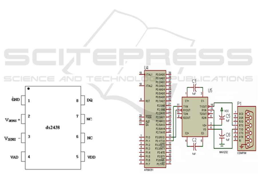
DS2438 pin assignment is shown in Figure 1:
DQ - data input / output
Vad - Universal A/D input
Vsens+ - the input terminal of the battery current
meter
Vsens- - the output terminal of the battery
current meter
Vdd - power supply side (2.4V ~ 10.0V)
GND - ground
NC - no definition (Jiapeng Yan,2011)
Figure 1: The leads package of the ds2438
2.2 MCU AT89C51 Brief Introduction
89C51 is a low power, low voltage, low price, high
performance 8 bit microcontroller, can be flexibly
applied in a variety of control areas. The on-chip
Flash ROM allowed in the system or use the
programmer and can be reprogrammed, cyclic
endurance up to one thousand times more than. The
thirtieth microcontroller AT89C51 pin ALE/PROG
is the address latch enable signal end of the pin
second function as the 89C51 chip Flash ROM to
burn into the curing procedure when the program
pulse input port, this paper uses the pin second
function, so it is set to a low level; the thirty-first pin
EA/ VPP is the external program memory address
allows input curing / programming input voltage,
when the pin is connected with the high level of
CPU, Flash and ROM access on-chip
implementation of internal ROM instructions in the
program counter, when more than 0FFFH, will
automatically turn off chip ROM to execute the
program, and when the pin low level, CPU will only
access off chip ROM in this paper, using the 51
compilers will program in curing the 4KB Flash in
ROM, so the pin is set to high state. AT89C51 serial
port and the serial communication technology, this
paper use 51 MCU programming realization, its
working principle is through the RS-232C interface
communication standard MAX232 SCM and PC
machine, 51 programmer procedures can be directly
burned into the microcontroller program memory 51,
its principle is shown in figure 2.(Fuzhao
Zhong,2014)
Figure 2: Schematic of 89c51’s serial communication
3 HARDWARE DESIGN SCHEME
51 MCU control display is used to display status
information users need to know the battery current,
the keyboard is the information input way for users
Design of Intelligent Battery Management System
347
Design of Intelligent Battery Management System
347
on the battery management system, the user can
control the microcontroller through the operation
button enter the corresponding interrupt subroutine,
the battery information collection. The sampling
system will be stored in the sampling parameters in
the DS2438 or 51 microcontroller with a nonvolatile
E2PROM or static ROM, so the system has the
function of power down protection. 51 single chip
microcomputer as the control and processing core of
the battery information collection subsystem, the
main software of the sampling control process was
completed, which obviously reduced the hardware
complexity of the system.
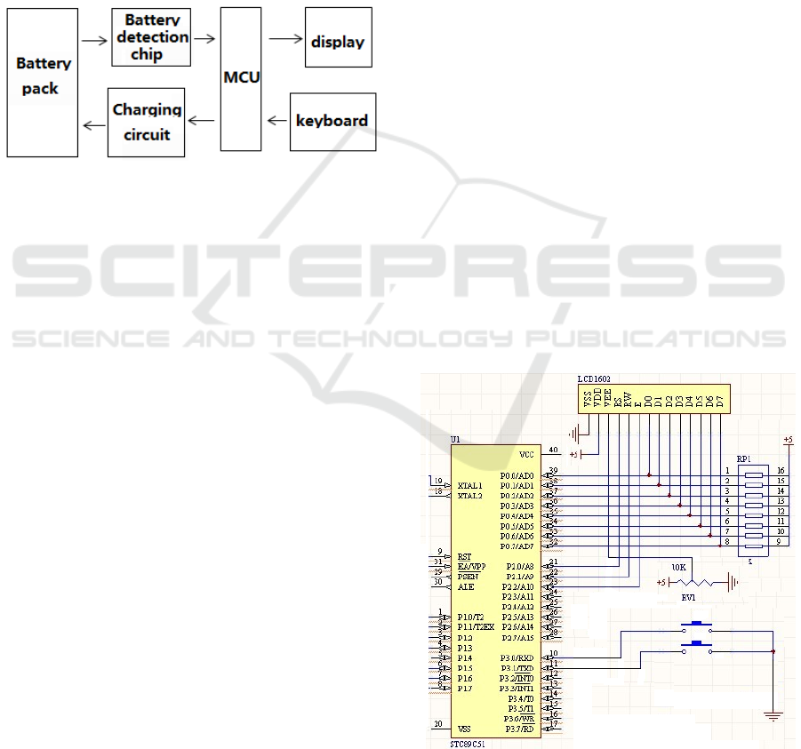
Figure 3: The structure of battery management system
Single chip using 89C51. Because the 89C51 chip
has ROM 4K, without further expansion of external
memory, the entire system is very simple. Single
chip and DS2438 data acquisition board potential, in
accordance with the communication protocol
provided by DALLAS company, in the way of field
bus data transmission, the following components of
the system.
Voltage measuring circuit : Using the built-in
DS2438 voltage A/D converter to measure the
terminal voltage of the entire set of cells. Because
the voltage measurement range of 0~10V is DS2438,
the terminal voltage of the battery group is 48V, so
the voltage dividing circuit is used to be applied to
the voltage measurement range of DS2438.
Current measuring circuit: Using the built-in
DS2438 current A/D converter to measure the
battery charge and discharge circuit. The sampling
resistance is connected to the battery charging
(discharging) electric circuit, and the charging and
discharging current of the battery can be measured
by measuring the resistance voltage drop of DS2438.
From the current built-in accumulator (ICA) chip,
automatically calculate the battery charge and
discharge current cumulative value of time, when
charging accumulated value is increased, and the
discharge is decreasing. After proper treatment, the
estimation of the remaining power of the battery can
be used.( Zhou Guan,,2015)
Temperature measurement: DS2438 chip close to
the battery, so as to measure the battery shell
temperature, and display and LCD display.
The cumulative ah : In order to estimate the
remaining battery charge and discharge, the total is
very important ah. When accumulated not by SCM
but by detection chip, DS2438 has a built-in current
accumulator (ICA), battery charge and discharge
current measurement of the cumulative value of
time, charge is accumulated, discharge is decreasing.
Cumulative value through the microcontroller, in the
liquid crystal display.
LCD: liquid crystal display selection is the 1602
LCD screen, the display is used to display the
battery voltage, current, power consumption, the
remaining power estimation, battery temperature.
The original design of the LED digital tube to
display the program, but the LED digital tube
display not only occupy more than SCM resources,
but also to maintain the LED digital tube display
requires a lot of energy consumption, to achieve the
display algorithm is relatively complex. LCD liquid
crystal display module and MCU connection
convenient, simple operation, and LED digital tube
display compared to take SCM less resources, and
low energy consumption, very suitable for the
controller design, the final selection of the LCD1602
display system information.
The LCD1602 used in the selection of the standard
16 pin (with a backlight), pin distribution as shown
in Figure4, pin is described below:
Figure 4 : Liquid crystal display circuit
ISME 2016 - Information Science and Management Engineering IV
348
ISME 2016 - International Conference on Information System and Management Engineering
348
4 SOFTWARE DESIGN OF THE
SYSTEM
The battery information collection subsystem
designed to access the DS2438 by the use of 51
single-chip keyboard scanning and monitoring
battery state parameters related to the acquisition,
the specific work process is as follows: first
initialize the 51 microcontroller, LCD display and
smart battery monitoring chip DS2438, and then
enter the keyboard scan subroutine, when scanning
to press a button, determine the key No., enter the
corresponding interrupt subroutine: DS2438 data
acquisition subroutine calls corresponding to, after
sampling, processed and displayed by the 51
microcontroller to read the collected data, and
finally return to the re initialization
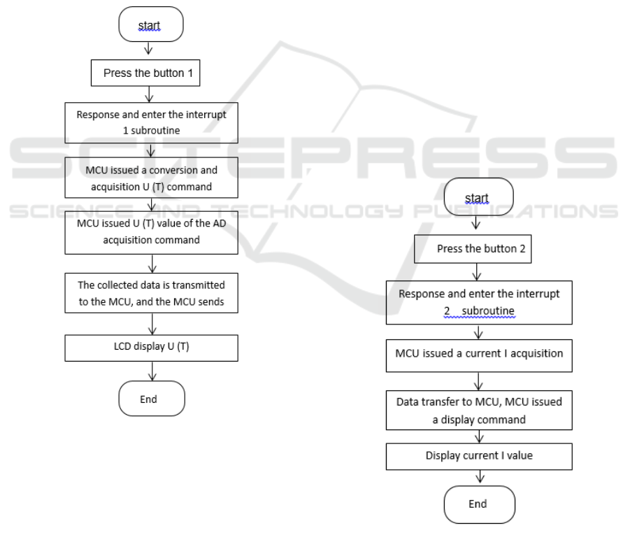
Figure 5 : The flow diagram of subprogram sampling
battery Voltage
The battery information collection subsystem to
monitor the battery voltage and temperature of the
sampling process is as follows: firstly, 51 MCU
detects a button 1 is pressed, determine the key
commands by 51 DS2438 microcontroller sends
control commands to collect voltage or temperature
response, and enter the interrupt 1 subroutine, MCU
by conversion of U (T) and U (T Collection)
command, U (T) acquisition, delay U (T)
transformation completed, the completion of U (T)
after conversion, MCU by U (T) AD acquisition
command value, collect the data to the
microcontroller through a single bus, single-chip
LCD display command issued, the acquisition of U
(T), end.
Before the 51 MCU ready to register is read the
contents of DS2438, to determine whether the
DS2438 sampling end, judgment method is through
the level of data line between DS2438 and 51
microcontroller, if the low level shows that the
sampling is ongoing, you cannot read the data, only
goes high can read the correct data. The battery
information collecting subsystem monitoring of
battery power supply mode and current sampling
process is as follows: first by 51 MCU commands
the current analog-to-digital converter DS2438, then
the smart battery monitoring chip DS2438 will
monitor the current sampling every 27.46ms the
battery automatically flows in and out, and the
results will be stored in the current register, then
read by the microcontroller 51, at the same time
through the S register in the current judgment to
judge the state of charge and discharge of the
battery, the software process is shown in figure6.
Figure 6 : The flow diagram of subprogram sampling
battery current
Design of Intelligent Battery Management System
349
Design of Intelligent Battery Management System
349

5 CONCLUSIONS
This paper takes DS2438 as the battery information
sampling chip, using AT8 9 C5 1 microcontroller to
control the core management to build battery
information collecting subsystem, and the lead-acid
battery 48V for the design of hardware and software
realization of battery information collection, which
is characterized by powerful function and low cost,
stable operation, reliable and in practical, our
experimental study shows a good performance. We
are willing to cooperate with the manufacturer, the
technology is applied to the industrialization and
industrialization.
ACKNOWLEDGEMENTS
The authors acknowledge the financial Supported by
a project grant from Huaian technology bureau
(Grand No.HAG2014007).
REFERENCES
Jiapeng Yan,Dazhi Wang,Youchao Jin, 2011.Detection of
High-power Battery Based on DS2438.
Microcontrollers & Embedded Systems.11,40-42
Zhou Guan, Chenxuan Li, Jiang Zhu, Ye Wu. 2015.
Design of large power battery power monitoring
system based on DS2438. Shandong Industrial
Technology,16,118-119
Fuzhao Zhong, 2014. 8051 MCU principle and software
and hardware design, Beihang University
press,Beijing, 2
nd
edition.
ISME 2016 - Information Science and Management Engineering IV
350
ISME 2016 - International Conference on Information System and Management Engineering
350
