
SEMF – The Semantic Engineering Modeling Framework
Bringing Semantics into the Eclipse Modeling Framework
for Space Systems Engineering
Tobias Hoppe
1,2
, Harald Eisenmann
1
, Alexander Viehl
2
and Oliver Bringmann
2,3
1
Airbus DS GmbH, 88039 Friedrichshafen, Germany
2
FZI Research Center for Information Technology, Haid-und-Neu-Str. 10-14, 76131 Karlsruhe, Germany
3
University of T
¨
ubingen, Sand 13, 72076 T
¨
ubingen, Germany
Keywords:
Model-based Systems Engineering, Conceptual Data Modeling, EMF, OWL, SMOF.
Abstract:
This paper presents an approach to integrate concepts realizing multiple classification and dynamic reclassifi-
cation into the Eclipse Modeling Framework (EMF) in order to overcome the restricted number of modeling
concepts of EMF and the strong class-object-relationship of Java. Hereby, the impact of integrating knowledge
modeling approaches – as realized with Prot
´
eg
´
e – into EMF without extending Java itself is examined. Conse-
quently, objects are configurable during the system development life-cycle by retyping. In combination with
reasoning functionality – as known from knowledge management frameworks – several pieces of knowledge
can be inferred and checked automatically as illustrated by examples from aerospace industry. As a result,
inconsistencies can be revealed much easier leading to considerably less potential for failures and a drasti-
cally reduction of follow-on costs. Significant improvements in areas like, object classification, knowledge
derivation, and guided system development, are highlighted in this paper.
1 INTRODUCTION
Many engineering domains, like mechanical, elec-
trical, optical, thermal, and software engineering,
are involved in nowadays systems engineering pro-
cesses dealing with a considerably large amount of
data and a multitude of data exchanges shaping a big
data environment. Proceeding with model-driven sys-
tems engineering requires a mapping of semantic con-
cepts close to those of the application domain, be-
cause semantics are strongly influenced by the used
tools rather than the data itself. Therefore, the in-
volved tools have to provide means to allow a com-
putational and human interpretation to form data into
knowledge enabling powerful model-based systems
engineering. Due to this, each domain uses special-
ized Commercial-Off-The-Shelf (COTS) tools com-
ing from different vendors. Consequently, each engi-
neering domain has to handle different technologies,
paradigms, file-formats, and semantics. This com-
plicates a domain-spanning collaboration. The out-
puts of these COTS tools as well as input documents
are stored in domain-specific engineering databases.
They are designed with respect to the requirements
of the COTS tools of a certain domain. Nonetheless,
they reflect only a specific section of the whole sys-
tem engineering life-cycle with limited collaboration
facilities which is a central aspect of nowadays sys-
tems engineering.
Model-Based Systems Engineering (MBSE)
(Friedenthal et al., 2007) is an upcoming topic in all
systems engineering areas. A central aspect of MBSE
is the usage of digital models during the whole
system development life-cycle. For the purpose of
providing a holistic system model as needed for
discipline-spanning MBSE, a suitable data structure
has to be kept by a software model to represent
all needed facets, like system abstraction levels,
domain-specific engineering data, discipline-specific
analysis, related reports, and project-specific tailoring
of data structures.
1.1 Necessity of Approach
For the European spacecraft engineering community
the emerging European standard ECSS-E-TM-10-23
is under development (ECSS-E-TM-10-23A, 2011).
It facilitates consistent cross-discipline management
Hoppe T., Eisenmann H., Viehl A. and Bringmann O.
SEMF â
˘
A ¸S The Semantic Engineering Modeling Framework - Bringing Semantics into the Eclipse Modeling Framework for Space Systems Engineering.
DOI: 10.5220/0006118702930301
In Proceedings of the 5th International Conference on Model-Driven Engineering and Software Development (MODELSWARD 2017), pages 293-301
ISBN: 978-989-758-210-3
Copyright
c
2017 by SCITEPRESS – Science and Technology Publications, Lda. All rights reserved
293

of data by specifying a Conceptual Data Model
(CDM) reflecting fundamental concepts of spacecraft
system design. An implementation of a System Ref-
erence Database (SRDB) based on this emerging stan-
dard is already in use in parts of the space indus-
try (Eisenmann et al., 2015). The CDM is realized
using the Unified Modeling Language (UML)(UML,
2015) and is transformed into a technology-specific
Ecore data model to enable code-generation based
on the state-of-the-art Eclipse Modeling Framework
(EMF)(Steinberg et al., 2008). The generated code
forms the core of the resulting SRDB and is extended
by data management functions which in turn are also
developed in a model-driven way.
On the one hand, the aforementioned implemen-
tation of ECSS-E-TM-10-23 offers all advantages of
model-driven software development during develop-
ment time of SRDB implementation as well as a
rather strong relation between CDM’s modeling ele-
ments and their corresponding data items of the im-
plementation. On the other hand, the major strug-
gling point is the weak semantics of EMF’s meta-
model, caused by missing modeling concepts, like
aggregations, and association classes. Additionally,
constraints can only be included into EMF while ex-
tending Ecore by the Object Constraint Language
(OCL) (OCL, 2012). Nonetheless, this is essential
to specify inter-association dependencies being used
for system data analysis, like specifying that each
satellite must have a specific number of orbit control
thrusters with a certain propulsion depending on its
total mass. Moreover, these constraints will be tai-
lored on each spacecraft development project to cover
mission specifics, for instance a satellite has two so-
lar arrays as default but for sun exploration missions
one solar array might be sufficient. Furthermore,
an SRDB implementation has to deal with multiple-
typed objects to realize that a system element is of
a certain equipment type which implies that corre-
sponding domain-specific data is correlated to it and
analysis data has to be woven into this system ele-
ment. For example, a system element can represent a
battery which implies that mechanical and electrical
engineering data has to be provided and this system
element is maintained by a configuration control sys-
tem to track which data version is correlated with each
other. Additionally, these multiple typed objects will
evolve over time by adding or removing parts of it.
The aforementioned needs of a MBSE supporting
framework are not specific to an ECSS-E-TM-10-23
implementation nor the space industry - instead all
developers of model-based applications dealing with
multiple typed objects, constraining, and tailoring ap-
proaches are faced with these problems. Research on
using ontologies to specify a CDM covering all the
aforementioned facets is already conducted by (Hen-
nig et al., 2015), (Hennig et al., 2016). Nevertheless,
the authors do not provide means to implement the
introduced concepts.
This paper presents an approach to overcome the
aforementioned set of shortcomings based on the Ob-
ject Management Group standard “MOF Support for
Semantic Structures” (SMOF) (SMOF, 2013), in the
following referred to as SMOF-standard. The follow-
ing two main contributions are elaborated in detail:
• Extension of EMF by the concepts of the SMOF
standard
• Elaboration of integrating reasoning into the EMF
environment
The following Section 2 focuses on the weak
points of actually used approaches to realize a
domain-spanning system data repository. Thereby,
the needs of introducing more semantic concepts are
pointed out. In Section 3 the integration of seman-
tic concepts into the Eclipse modeling Framework is
described in detail and the benefits of the approach
presented in this paper are evaluated by a case study
outlined in Section 4. Finally, this paper concludes in
Section 5.
2 MBSE IN EUROPEAN
SPACECRAFT ENGINEERING
An SRDB implementing the ECSS-E-TM-10-23
CDM has to deal with multiple architectural and tech-
nical implications. It prevents redundancy through di-
rect usage of data provided by other domains instead
of working with data from a domain-specific storage.
It is the foundation for consistent data management
regarding both the consistency within a dataset from
a single domain as well as domain-spanning consis-
tency due to having a single data source to execute
domain-spanning tasks, like simulations, and system
validations.
2.1 Identified Weak Points of the CDM
Implementation
Implementing the concepts of the ECSS-E-TM-10-23
CDM leads to multiple design decisions concerning
the used technology-specific data model. This in turn
influences the resulting SRDB implementation.
An explicit part of the emerging standard ECSS-
E-TM-10-23 is the decomposition of a system ele-
ment into other system elements, different kinds of
MODELSWARD 2017 - 5th International Conference on Model-Driven Engineering and Software Development
294

related entities, owned values, as well as its represen-
tation of an equipment type related with discipline-
specific engineering data. In addition, the equipment
types have to be own objects which shall be reused
in further projects whereby the system elements are
project-specific. This enforces some kind of multiple-
type object to reflect the different facets of a system
element and fulfill ECSS-E-TM-10-23 conformity in
all details. Feasibility of implementing these concepts
is enforced by enhancing a CDM by needed items.
This will be called implicit knowledge.
Another category of type change during spacecraft
evolution is introduced by adding data management
functions’ data to system data. Taken the use case
that after creating a system element it shall be added
to a configuration control system, the system element
type has to be enhanced. It has to become a config-
uration item to store all information needed for con-
figuration control, like revision number, commit mes-
sage, and some more. Additionally, the meta-model
for function-specific data has to be aligned with the
CDM which implies that the function meta-model
has to be conform to the used technology-specific
data model. Consequently, function-specific aspects
are woven into the technology-specific data model or
even in a CDM to ease up function integration.
During development of a spacecraft the evolution
of system data may lead to an update of a system el-
ement, where its type is adjusted. This is for instance
the case when a battery of a spacecraft is represented
by a single system element in an early version of the
system data. During system data evolution it will
make sense at a certain point to break down the bat-
tery into multiple system elements to properly repre-
sent the individual parts of it, such as energy storage,
controller, and structure. This change leads to a type
change of the system element representing the over-
all battery from equipment to subsystem which influ-
ences the handling of this system element by overall
system data analysis, like system-wide data consis-
tency checking.
Project-specific tailoring is a central functional-
ity in SRDB implementations to enable inter-project
reuse of knowledge and engineering data. There-
fore, some parts of a CDM have to be adjusted to
reflect project specifics. This enforces some kind
of data container being configured in SRDB itself
to handle domain-specific system element properties,
like weights, sizes, temperatures, voltages, and so
on. Data analysis of these dynamic data containers is
challenging especially regarding overall system con-
straints, like total spacecraft mass constraints. Be-
sides, a manually adjustment of SRDB is applied to
face with project-specific data importer and exporter,
because it is currently not feasible to handle them oth-
erwise.
2.2 Related Work on
ECSS-E-TM-10-23
Implementations
The ECSS-E-TM-10-23 CDM has been implemented
in multiple projects, like Virtual Spacecraft De-
sign (VSD, 2012), Functional System Simulation in
Support of MBSE (Fischer et al., 2014), European
Ground Systems Common Core (Pecchioli et al.,
2012), and RangeDB (Eisenmann et al., 2015), an
Airbus DS in-house development project which sig-
nificantly improved this CDM by evolution and re-
finement of several areas.
Nevertheless, the concepts specified by ECSS-E-
TM-10-23 have not been realized in its entirety by
any of its implementations, especially due to miss-
ing multiple classification concepts in state-of-the-art
software development frameworks and its ramifica-
tions. Even the usage of interfaces is not sufficient
to realize multiple instantiation, because dynamic ad-
dition and removing of types cannot be realized as all
instances already implement all possible types. Thus
it is not possible to filter objects by type using inter-
faces. Additionally, project-specific tailoring requires
handling of types being created during runtime.
In contrast, knowledge representation languages,
like the Web Ontology Language (OWL)(Hitzler
et al., 2012), explicitly support multiple classifica-
tion and other knowledge management concepts. Al-
beit, available frameworks for these languages, like
Prot
´
eg
´
e, do not provide data management functions
as needed for MBSE.
2.3 Drawbacks of State-of-the-art
Frameworks
EMF: provides a powerful tool chain from model
definition, through application generation, to instance
model support. Furthermore, a great number of plug-
ins has been developed to add further functionality to
EMF. As a result, EMF became the de facto-standard
for model-driven software development in many com-
panies
1
. However, Ecore – EMF’s meta-model – is
not sufficient to fulfill the needs of a data model as
required by an implementation of an ECSS-E-TM-10-
23 compliant CDM. The main reason is the absence of
semantically strong modeling constructs which have
been left out intentionally to keep the complexity of
EMF manageable (Merks, 2010).
1
http://www.eclipse.org/org
SEMF â
˘
A¸S The Semantic Engineering Modeling Framework - Bringing Semantics into the Eclipse Modeling Framework for Space Systems
Engineering
295

Prot
´
eg
´
e: is a state-of-the-art knowledge manage-
ment framework (Gennari et al., 2003). It is based
on the OWL meta-model. Prot
´
eg
´
e provides functions
to model ontologies as well as it is shipped with inte-
grated reasoners to derive knowledge about instance
models based on user-defined rules. All in all, Prot
´
eg
´
e
provides excellent means to model ECSS-E-TM-10-
23 conform CDMs, due to its semantically strong
knowledge modeling and knowledge derivation ap-
proaches.
Nonetheless, there are only limited possibilities to
generate code from modeled ontologies. Prot
´
eg
´
e and
other known knowledge management frameworks are
designed for model development and do not explic-
itly support software development – especially for an
SRDB implementation. This is an essential drawback.
2.4 Related Approaches to Realize
SMOF Concepts
A similar realization of the multiple classification ap-
proach than described in the SMOF standard is real-
ized by an Eclipse Java compiler extension provided
by the ObjectTeams group (Herrmann, 2007), (Her-
rmann et al., 2007). They extend Java classes to de-
fine certain so called Roles which can be played by
instances of a class. Using this approach an object
can play multiple roles and an object’s behavior de-
pends on the roles it plays. Furthermore, adding and
removing a role will not change an object’s identity.
In addition, the operations defined by a role can be
applied as known.
All in all, this reflects the multiple classification
concept as specified by the SMOF standard. Never-
theless, the ObjectTeams approach is geared to the
ObjectTeams Java compiler for Eclipse which is not
updated as often as the Eclipse built-in compiler and
a dynamic reclassification is limited on the number
of roles defined during design time of engineering
framework and cannot be changed afterwards.
Martin Fowler presents several design patterns on
how to realize different variants of multiple classifica-
tion by discussing their individual benefits and draw-
backs (Fowler, 1997) on a conceptual level. Nonethe-
less, implementations of the presented patterns have
to deal with programming language specific concerns,
like multiple inheritance, which is not supported in
Java but in other languages, like C++, and is a key
feature to realize SMOF’s multiple classification.
3 SEMANTIC EMF
Semantic EMF synergistically combines knowledge
modeling concepts and the SMOF concepts in con-
junction with EMF to enable a semantically stronger
modeling of data structures appropriately reflecting
constructs of the real world.
3.1 SMOF Concepts
The SMOF standard defines two major concepts –
multiple classification and dynamic reclassification –
reflecting the semantic extension of the MOF stan-
dard.
Multiple Classification: as specified by the SMOF
standard defines an object’s type as the union of struc-
tural and behavioral features defined by all of its inde-
pendent meta-classes – which can be more than one.
Dynamic Reclassification: is specified by the
SMOF standard as an ability to modify an object’s
type by adding or removing meta-classes without
changing the object’s identity.
3.2 Impact on CDM Implementations
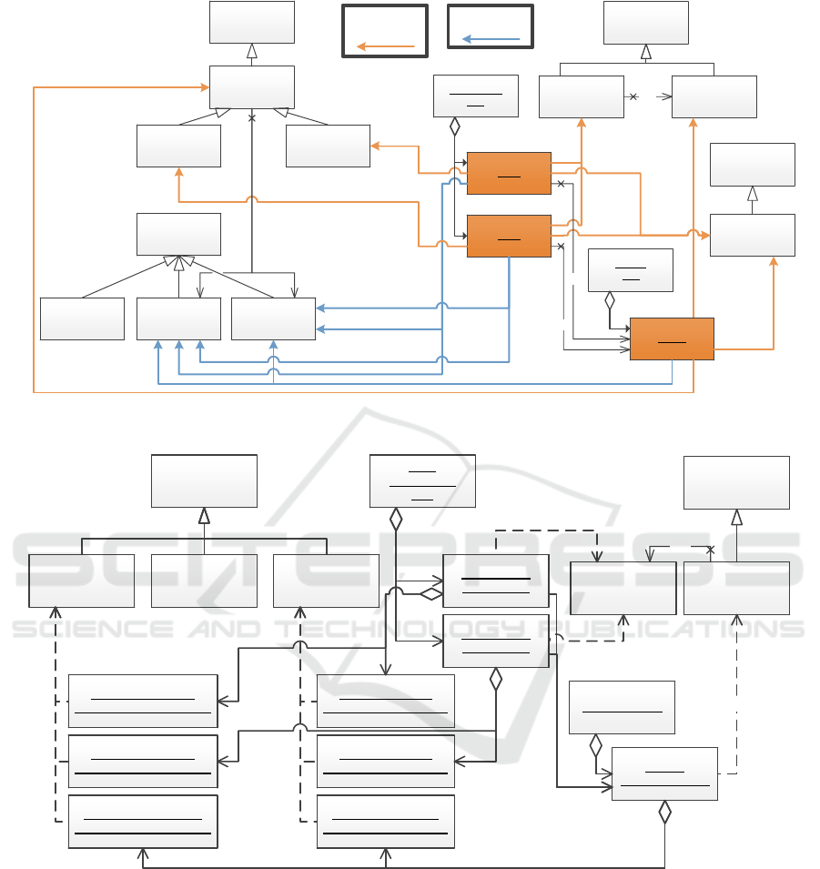
In Figure 1 an excerpt of the ECSS-E-TM-10-23
CDM is illustrated. It focuses on the central concept
of this emerging standard, namely the composition of
a System element of related system engineering data.
Thereby, the correlation between the different System
Element sub-types plays an important role. An Ele-
ment Definition represents a class of elements being
used in a spacecraft, like an solar array, and an Ele-
ment Configuration represents a concrete instance of
an element definition type, like left solar array, right
solar array, and so on. This relation is represented by
the type relation. As a result, all data related to an
Element Definition is also valid in the scope of all El-
ement Configurations having this Element Definition
as type until they override it. In the example given
in Figure 1 the Battery instance of Element Definition
is the type for the two instances of Element Configu-
ration. Consequently, the two Element Configuration
instances have to be a Battery Equipment Type which
in turn results in having mechanical and electrical en-
gineering properties for each of them. Using reason-
ing functionality as available in Prot
´
eg
´
e this might be
derived from the relations between Equipment Types
and Property Containers.
Additionally, data necessary to perform systems
engineering, like configuration control information,
MODELSWARD 2017 - 5th International Conference on Model-Driven Engineering and Software Development
296
Equipment
Type
PropertyContainer
Element
Definition
System
Element
Battery
Mechanical
Engineering Data
Electrical
Engineering Data
Configuration
Tree
BAT 1
Must be
Instance of
Battery
Optical
Engineering Data
Battery_S Battery_XL
BAT 2
Must be
Instance of Battery
Function
Meta Data
Configuration
Item
Element
Configuration
1
type
Product
Tree
Battery
Instance of Relation
Derived by reasoner
Conceptually
Instance of
type
type
1
1
requires
Figure 1: Relations between system elements, equipment types, and domain data as defined by ECSS-E-TM-10-23.
Property
Container
Element
Definition
System
Element
Mechanical
Engineering Data
Electrical
Engineering Data
SC: Product Tree
Battery:
ElementDefinition
Optical
Engineering Data
<<instanciate >><<instanciate>>
<<instanciate>>
ElectricalBatteryData:
ElectricalEngineeringData
MechanicalBatteryData:
MechanicalEngineeringData
SC_1:
Configuration
Tree
Bat1: Element
Configuration
Bat2: Element
Configuration
Element
Configuration
1
type
<<instanciate>>
<<instanciate>>
Bat1ElectricalData:
ElectricalEngineeringData
Bat2ElectricalData:
ElectricalEngineeringData
Bat2MechanicalData:
MechanicalEngineeringData
Bat1MechanicalData:
MechanicalEngineeringData
type
Figure 2: Technology-specific data model reflecting the same relations as shown in Figure 1.
related documents, related simulation data, domain-
specific data representations, and many more is at-
tached in form of Function Meta Data.
The excerpt of the ECSS-E-TM-10-23 CDM
shown in Figure 1 cannot be implemented using EMF
without changes to emulate the needed multiple clas-
sification behavior. Current implementations of this
CDM introduce additional relations and special func-
tions to represent the expected behavior as illustrated
in Figure 2. In this case the engineering data in-
stances are explicitly available as own instances and
contained by the corresponding System Elements. The
Equipment Types are implicitly available by the name
of a System Element and the relations between Sys-
tem Elements and domain data are realized by adding
proper dynamic Property Container instances to cor-
responding System Elements.
The Function Meta Data instances have been in-
tentionally left out in this figure, but they are handled
like Property Containers. The functional dependency
SEMF â
˘
A¸S The Semantic Engineering Modeling Framework - Bringing Semantics into the Eclipse Modeling Framework for Space Systems
Engineering
297

between an Element Definition and an Element Con-
figuration is handled by internal functions. Neverthe-
less, it is not ensured that an Element Configuration
instance has the same engineering data types as the
corresponding Element Definition. The introduction
of such implicit semantics in nowadays implementa-
tions leads to different interpretations of data by engi-
neers. Thus, it is an essential drawback.
3.2.1 Multiple Classification Impacts
Multiple classification is needed to realize a Sys-
tem Element as introduced by ECSS-E-TM-10-23 and
highlighted in Figure 1. In this case the Battery is an
instance of Element Definition, Configuration Item,
Battery Equipment Type, as well as of the inferred
Property Container – Mechanical Engineering Data
and Electrical Engineering Data. It properly reflects
the relations as specified by ECSS-E-TM-10-23 with-
out introducing implicit knowledge by the implemen-
tation.
A further advantage of the usage of multiple clas-
sification in this scenario is the reduced maintenance
effort due to CDM changes resulting only in changed
types, although in current implementations the intro-
duced technical adjustments of the CDM have to be
maintained. Moreover, maintenance of engineering
frameworks will be significantly reduced due to sepa-
ration of core concept data and function specific data,
because the usage of multiple classification would en-
able a fine-grained providing of function meta-data
without adjustment of the System Element class or any
of its sub-classes. For example, the introduction of a
new Function Meta Data type can be performed with-
out touching the System Element class and on instance
level by putting it into the types list of an existing
System Element instance. This allows detailed track-
ing for dependencies of system engineering functions
and is a basement for a flexible systems engineering
framework architecture.
Additionally, multiple classification allows engi-
neers to filter system elements according to their
equipment type or the domains they provide data for.
The implementation of such filter functions is signif-
icantly less complex, because objects need to be fil-
tered only according to their type, whereas in nowa-
days implementations the relations introduced only
for the implementation need to be evaluated.
3.2.2 Dynamic Reclassification Impacts
Dynamically adding and removing object types dur-
ing an object’s life-cycle comes up with several use
cases in scope of realizing the vision of ECSS-E-TM-
10-23. One of the major benefits is the evolution of an
object by adding further types. Regarding the exam-
ple CDM given in Figure 1 this can be used to build
up a System Element by adding its Equipment Type
and afterwards adding the Property Container. Addi-
tionally, the object can be enhanced by Function Meta
Data types. This step-by-step evolution of an object
– where an existing object is enhanced by additional
data and behavior – enables step-wise forming of an
object without the need to provide classes for all al-
lowed combinations.
Project-specific tailoring is achieved in current
implementations by introducing configurable prop-
erty containers which can be configured by project
managers during runtime of SRDB, like Property
Container in the example illustrated in Figure 1. Af-
terwards, systems engineers instantiate these config-
ured Property Containers to store their actual data
values. With the help of dynamic reclassification
the current project-specific tailoring approach can be
enhanced by handling the aforementioned Property
Containers like all other classes. This means that
adding a Property Container to a certain System El-
ement will no longer be realized by a certain relation.
Instead, a Property Container will be handled like a
new type of a System Element instance and is simply
added to the already available set of types.
As a result, only simple type checks are needed
to figure out whether a certain Property Container is
applied to a System Element or not, whereas in current
implementations all property container instances of a
system element must be analyzed to check whether
the searched one is present or not.
Although dynamic reclassification simplifies sys-
tem engineering tasks and MBSE framework devel-
opment, it enforces an additional constraining mech-
anism to prevent system engineers from using certain
object type combinations that make no sense from
overall system point of view, such as disjoint types,
like actor and sensor.
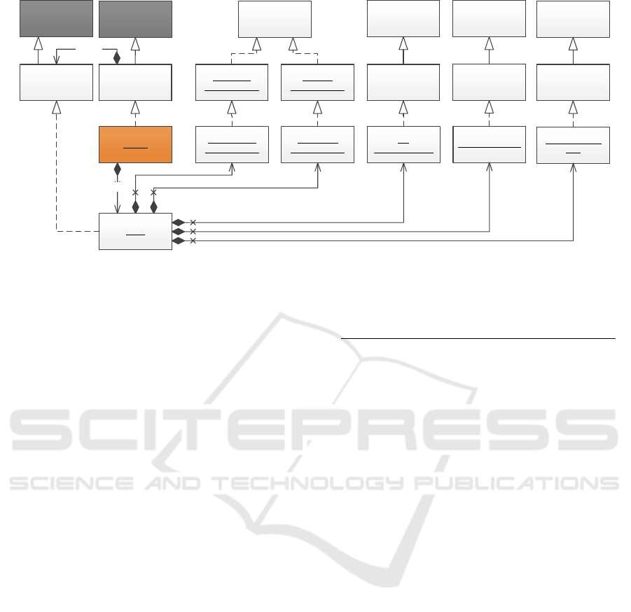
3.3 Semantic EMF for MBSE
In Figure 3 an EMF-based implementation for multi-
ple classification is introduced. Thereby, an SObject
reflects its types by a Type Registry that contains all
mappings from a class type to the corresponding in-
stances. In the given example the SObject instance
Battery is build up by the five different types being
connected to the contained Type Registry. Addition-
ally, each SObject provides the following functions:
• getting all classes registered in type registry
• check whether this element is an instance of a
given type
• add a new type
MODELSWARD 2017 - 5th International Conference on Model-Driven Engineering and Software Development
298
EObject
SObject
Battery
Equipment Type
Configuration Item
Battery
Type Registry
<Class, EObject>
1
typeReg
Bat
ElementDefinition
BatEquipmentType
BatConfiguration
Item
Types
1
typeReg
1
Element Definition
1
Battery
1
Configuration Item
Property
Container
Mechanical
EngineeringData
1
Mechanical Engineering Data
BatMechanical
EngineeringData
Equipment
Type
Element
Definition
System
Element
Function
Meta Data
EMap
Electrical
EngineeringData
BatElectrical
EngineeringData
1
Electrical Engineering Data
Figure 3: Implementation for multiple classification representing the scenario introduced in Figure 1.
• remove an existing type
• provide access to covered instances of registered
types
• check whether a given type can be assigned to the
SObject instance or not based on available set of
rules
The handling of Property Containers differs from
other types, because they are configurable during run-
time by adding further project-specific properties or
adjustment of existing ones which is part of ongoing
research.
3.4 New Functions by Semantic EMF
The semantic concepts illuminated in Section 3.1
are the foundation to integrate reasoning – a cen-
tral knowledge management functionality – into an
SRDB. A reasoner can be used to evaluate model va-
lidity by checking logical model coherence and user-
defined rules. In addition, new information can be
derived from existing data using a reasoner’s data in-
ference functionality.
A less obvious scenario for knowledge derivation
than given in Figure 1 is the following: A Sensor is
defined as Magnetic Instrument and the CDM con-
tains a rule that each spacecraft containing a Magnetic
Instrument is a Magnetic Critical Spacecraft. This re-
lation can be inferred by the reasoner. Furthermore,
there is a rule that each Battery being part of a Mag-
netic Critical Spacecraft must be of type Magnetic
Critical Battery. The needed instance-of relation can
be inferred by a reasoner, too. A wide range of such
rules is already available and leads to less error-prone
and more consistent system models.
Table 1: Number of selected data types in the satellite
project used for evaluation of semantic concepts.
# Objects
Element Definition 50
Element Configuration 150
Domains 11
Equipment Types 40
Dynamic Configuration Classes 20
Dynamic Configuration Instances 1600
4 CASE STUDY
This section illustrates the impact of semantic con-
cepts as proposed in Section 3 on a spacecraft de-
sign project being at the end of Phase B of European
Space Agency’s mission lifetime cycle which reflects
the preliminary design definition phase (ECSS-E-ST-
10C, 2009).
Evaluation Project Setup. The virtual spacecraft
design project data presented in this paper represents
a realistic project in terms of used number of el-
ements, involved domains, and overall complexity.
ECSS-E-TM-10-23 defines four sub-types of system
elements. In this paper only the Element Definition
and the Element Configuration are of interest, because
the other two types are only relevant for later phases
of spacecraft design and will not introduce any further
concepts or complexities.
The excerpt of the CDM defined by ECSS-E-TM-
10-23 as shown in Figure 1 is taken as starting point
to show how semantic concepts and data management
functions from knowledge modeling frameworks are
integrated to improve semantics and how they can
SEMF â
˘
A¸S The Semantic Engineering Modeling Framework - Bringing Semantics into the Eclipse Modeling Framework for Space Systems
Engineering
299

help to reduce system development costs.
The introduction of semantic concepts enables the
employment of Equipment Types as self-contained
model elements which can be reused by several sys-
tem elements even in multiple projects whereby in
the current implementation the Equipment Types are
only represented by a System Element’s name (see
Figure 2 Battery), because a System Element can-
not extend multiple classes in Java. From a model-
ing point of view it is possible to inherit from multi-
ple classes in EMF. Due to missing multiple inher-
itance in Java this results in duplicated implemen-
tation code and non-generated parts of classes can-
not be used properly. Consequently, multiple inheri-
tance is avoided in actual implementations of ECSS-
E-TM-10-23 and technology-specific model adjust-
ments have been realized as pointed out in Sec-
tion 3.2. Introducing multiple classification in EMF
opens the door to model and implement the Equip-
ment Types as specified in ECSS-E-TM-10-23. As
a result, a relation between Property Container and
Equipment Types can be modeled to specify the ex-
pected domain data for an Equipment Type as illus-
trated in Figure 1. As soon as a System Element
instance is related to an Equipment Type the corre-
sponding Property Container types are automatically
inferred by the reasoner and must not manually be
managed by a systems engineer any longer. If mul-
tiple variants of a spacecraft are designed, this can
be used to ensure the same behavior for all variants
by reusing the Equipment Types and their relations to
Property Container. In this scenario 280 relations can
be reused by other projects.
Regarding the model in Figure 1 multiple classifi-
cation is an enabler to realize project-specific tailoring
of the CDM by dynamic object composition. In this
case, all instances of dynamic configuration classes,
like Property Container, and Equipment Types, can
play a role as part of a System Element. In this sce-
nario 1600 dynamic configuration instances can be
used as concrete parts of System Elements forming
their specific type set.
Based on the foundation given by multiple clas-
sification a reasoning functionality as known from
knowledge modeling frameworks can be used to make
implicit available knowledge explicit. As presented
in Figure 1 a reasoner can derive which domain-data
is needed for a system element representing a cer-
tain Equipment Type by evaluating the newly intro-
duced relation between Equipment Type and Property
Container. In the context of the evaluated spacecraft
design project the reasoner derived 350 relations for
Element Definitions, due to the fact that an Element
Definition is related to Property Container of seven
domains in a common project. On Element Configu-
ration level the number of inferred relations is about
1050 based on 150 Element Configurations having
overall domain data from seven domains.
Dynamic reclassification and multiple classifica-
tion go hand in hand while working with system data.
The system data illustrated in Figure 1 will be built-
up step by step still leading to a reclassification of a
system element by adding the Equipment Type as ad-
ditional type. Moreover, a System Element can be
extended by Function Meta Data types as soon as
data management functions are applied. In the given
scenario many reclassifications take place. In gen-
eral, each System Element is reclassified at least twice.
First, by adding the Equipment Type and second, by
adding the corresponding Property Container. Addi-
tionally, applying Function Meta Data, as shown in
Figure 1, will result in further reclassifications.
All in all, these concepts are 100 percent back-
ward compatible and can be incrementally applied in
existing software solutions. In addition, they are to-
tally compatible to Eclipse and EMF and follow the
Java principles (Gosling, 2000).
5 CONCLUSION
The integration of semantic and knowledge model-
ing concepts into the Eclipse Modeling Framework
(EMF) leads to a flexible way of working with data
during runtime. Especially, the Semantic Meta-
Object Facility concepts – multiple classification and
dynamic reclassification – fundamentally change the
way of implementing conceptual models.
Thereby, the composition of objects during run-
time provides the needed freedom for flexible space-
craft design supporting the whole engineering life-
cycle. For data management support data flows can
be easier traced between domain-specific commercial
of the shelf tools and the system database. Addi-
tionally, new functions supporting data exploitation
in terms of rule-based analysis and automatic type
conclusions using reasoning functionality will signif-
icantly improve the engineering process. Moreover,
domain-specific views can be defined for domain en-
gineers based on the domain data types of a system
element.
Following an explicit semantic handling, the ab-
sence of domain data as well as the additional non-
expected availability of domain data will lead to in-
consistencies of overall system data that can be re-
ported to the user as soon as the reasoner is running.
The integration of an additional system element
into a current system element tree may influence the
MODELSWARD 2017 - 5th International Conference on Model-Driven Engineering and Software Development
300

type of other system elements, such as a magne-
tometer being added to a satellite’s system element
tree will transform the whole satellite into a mag-
netic critical spacecraft. Once defined, such rules
can be reused in ongoing projects to optimize sys-
tem data consistency checks and build the foundation
for guided systems engineering through the whole
system life-cycle significantly reducing data inconsis-
tency potential. An overview on this is already given,
but concrete implementations for guided systems en-
gineering are part of further research.
REFERENCES
ECSS-E-ST-10C (2009). ECSS European Cooperation
for Space Standardization, “ECSS-E-ST-10C - Space
Engineering - System engineering general require-
ments”. ECSS Secretariat ESA-ESTEC Requirements
& Standards Division.
ECSS-E-TM-10-23A (2011). ECSS European Coopera-
tion for Space Standardization, “ECSS-E-TM-10-23A
- Space Engineering - Space System Data Reposi-
tory”. ECSS Secretariat ESA-ESTEC Requirements
& Standards Division.
Eisenmann, H., Cazenave, C., and Noblet, T. (2015).
RangeDB the Product to Meet the Challenges of
Nowadays System Database. 9th ESA Workshop on
Simulation for European Space Programmes.
Fischer, P., Eisenmann, H., and Fuchs, H. (2014). Func-
tional Verification by Simulation based on Preliminary
System Design Data. 6th International Workshop on
Systems and Concurrent Engineering for Space Appli-
cations.
Fowler, M. (1997). Dealing with roles. In Proceedings of
PLoP, volume 97.
Friedenthal, S., Griego, R., and Sampson, M. (2007). IN-
COSE Model Based Systems Engineering (MBSE)
Initiative. INCOSE MBSE Track.
Gennari, J. H., Musen, M. A., Fergerson, R. W., Grosso,
W. E., Crub
´
ezy, M., Eriksson, H., Noy, N. F., and
Tu, S. W. (2003). The evolution of prot
´
eg
´
e: an
environment for knowledge-based systems develop-
ment. International Journal of Human-computer stud-
ies, 58(1):89–123.
Gosling, J. (2000). The Java language specification.
Addison-Wesley Professional.
Hennig, C., Eisenmann, H., Viehl, A., and Bringmann, O.
(2015). On languages for conceptual data model-
ing in multi-disciplinary space systems engineering.
In Model-Driven Engineering and Software Develop-
ment (MODELSWARD), 2015 3rd International Con-
ference on, pages 384–393. IEEE.
Hennig, C., Viehl, A., K
¨
ampgen, B., and Eisenmann, H.
(2016). Ontology-based design of space systems. In
International Semantic Web Conference, pages 308–
324. Springer.
Herrmann, S. (2007). A precise model for contextual roles:
The programming language objectteams/java. Applied
Ontology, 2(2):181–207.
Herrmann, S., Hundt, C., and Mosconi, M. (2007). Object-
teams/java language definition.
Hitzler, P., Krotzsch, M., Parsia, B., Patel-Schneider, P. F.,
and Rudolph, S. (2012). Owl 2 web ontology language
primer.
Merks, E. (2010). Eclipse Modeling Framework – Interview
with Ed Merks. http://jaxenter.com/eclipse-modeling-
framework-interview-with-ed-merks-10027.html.
OCL (2012). Object Constraint Language (OCL). Ob-
ject Management Group, http://www.omg.org/spec/
OCL/2.3.1.
Pecchioli, M., Walsh, A., Carranza, J. M., Blommestijn, R.,
Charmeau, M.-C., Geyer, M., Stangl, C., Parmentier,
P., Eisenmann, H., Rueting, J., et al. (2012). Objec-
tives and concepts of the european ground systems
common core (egs-cc). In Simulation & EGSE Fa-
cilities for Space Programmes (SESP) Workshop.
SMOF (2013). MOF Support for Semantic Struc-
tures (SMOF). Object Management Group, http://
www.omg.org/spec/ SMOF/1.0/.
Steinberg, D., Budinsky, F., Merks, E., and Paternostro, M.
(2008). EMF: eclipse modeling framework. Addison-
Wesley Professional.
UML (2015). Unified Modeling Language (UML). Ob-
ject Management Group, http://www.omg.org/spec/
UML/2.5.
VSD (2012). Virtual Spacecraft Design. European Space
Agency (ESA), http://vsd.esa.int/.
SEMF â
˘
A¸S The Semantic Engineering Modeling Framework - Bringing Semantics into the Eclipse Modeling Framework for Space Systems
Engineering
301
