
Model-to-Model based Approach for Software Component Allocation in
Embedded Systems
Lujain Al-Dakheel and Issam Al-Azzoni
Department of Software Engineering, College of Computer and Information Sciences,
King Saud University, Riyadh, Saudi Arabia
Keywords:
Component Allocation, Coloured Petri Nets, Unified Modeling Language, Model-Driven Engineering,
Embedded Systems, Heterogeneous Systems, Model-to-Model Transformation.
Abstract:
Due to the popularity and heterogeneity of embedded systems, the problem of software component (SW-
component) allocation in such systems is receiving increasing attention. Addressing this problem using a
graphical modeling language such as Ecore will enable system designers to better and more easily allocate their
components. However, the existing Ecore models do not address the problem of SW-component allocation in
heterogeneous embedded systems. Because of Ecore informal semantics, Ecore models cannot be analyzed
using mathematical tools. On the other hand, an approach based on colored Petri nets (CPNs) was proposed
for the modeling and analysis of the software component allocation problem. The approach was shown to
be applicable in the field not only with respect to the cost optimization problem, but also because it takes
nonfunctional requirements into consideration. In this paper, we propose an approach for the automated
transformation of an Ecore model into an equivalent CPN model, which will help the modeler use the power
of a formal modeling language by only modeling the system using a simple Ecore-based modeling language.
1 INTRODUCTION
Model Driven Engineering (MDE) uses models as a
cornerstone throughout the software lifecycle, which
indicates a shift from everything is an object paradigm
to everything is a model paradigm (Wimmer et al.,
2011). In this context, choosing a good model will
lead to a better system. Ecore is a powerful, ex-
pressive and rich language used to define metamodels
conformed to EMF (Eclipse Modeling Framework)
1
.
The semantics of Ecore is not formally expressed.
Thus models defined in Ecore are difficult to analyze.
On the other hand, CPN (Petri and Reisig, 2008) is
a mathematical modeling language offering detailed
view of the modeled system with a graphical repre-
sentation. Also, models by CPN can be analyzed us-
ing powerful tools (such as CPN Tools
2
). These prop-
erties have made CPN popular in modeling, analyz-
ing, and optimizing complex systems.
SW-component allocation is the process of map-
ping SW-component to the computational units. Re-
cently, many existing research studies focus on the
modeling of these components and verifying these
1
http://wiki.eclipse.org/EMF
2
http://cpntools.org/
models in an effective way. The SW-component al-
location has not been modeled neither in Ecore (Bier-
mann et al., 2008) nor in UML (Force, 2010).
As known, model transformation is a key process
in MDE. For that, in this research we aim to introduce
an automated transformation technique to automati-
cally generate a CPN model that addresses the SW-
component allocation problem specified in a given
Ecore model in order to help the modeler access the
full benefits of the formal modeling language without
necessarily creating the CPN model. The contribu-
tions of the paper are summarized as follows:
1. We create a new Ecore model for the SW-
component allocation.
2. We automatically transform the Ecore model into
an equivalent CPN’s model
3. We automatically re-write the CPN model us-
ing a Java parser program that obtains the output
from ATL and transforms it into the required CPN
Tools format.
The organization of the paper is as follows. In Section
2, we define the preliminaries used in our paper. We
illustrate our approach in Section 3 and evaluate it in
Section 4. The related work is discussed in Section
320
Al-Dakheel L. and Al-Azzoni I.
Model-to-Model based Approach for Software Component Allocation in Embedded Systems.
DOI: 10.5220/0006126903200328
In Proceedings of the 5th International Conference on Model-Driven Engineering and Software Development (MODELSWARD 2017), pages 320-328
ISBN: 978-989-758-210-3
Copyright
c
2017 by SCITEPRESS – Science and Technology Publications, Lda. All rights reserved

5. Section 6 concludes the paper and outlines future
work.
2 PRELIMINARIES
2.1 CPN
Colored Petri nets (CPN) are an extension of the con-
cept known as Petri nets (Petri and Reisig, 2008).
CPNs sustain the useful properties of Petri nets and
extend them with initial formalism to allow differ-
ences between tokens (Jensen, 2013). CPN is a for-
mal, general-purpose modeling language. In CPNs,
tokens are stored in places that carry data (or colors)
of a given type. CPN is a discrete-event modeling
language combining the capabilities of Petri nets with
those of a high-level programming language. A sys-
tem model in CPN contains both states and action-
oriented behaviors. The CPN model describes the
states of a system and the events (transitions) that can
cause the system to change its state (Jensen and Kris-
tensen, 2009).
2.2 Software Component Allocation for
Embedded Systems
An embedded system is a computer system and its
related software built into a piece of equipment (Carl-
son et al., 2010). Recently, significant effort has
been done on developing and maintaining embedded
systems, including SW-component allocation. SW-
component allocation is the process of mapping SW-
component to the computational units. Consider a
software system (
ˇ
Svogor et al., 2014a) consisting of
n components; each component must be assigned to a
computational unit on a hardware platform consisting
of m computational units. The computational units of-
fer a number of resources l. The component resource
consumption matrix
T = [t
i jk
]
(n×m×l)
defines the resources required by each component.
The computational unit resource capacity matrix
R
R = [r
jk
]
(m×l)
defines the resources that each computational unit can
provide. The component allocation problem seeks to
find an allocation (p
1
, ...., p
n
), where component i is
allocated to computational unit p
i
, which is both fea-
sible and optimal. The feasibility condition can be
stated as follows: Given an allocation (p
1
, ..., p
n
), for
all computational units j:
∑
i, p
i
= j
(t
ip
i
k
) ≤ r
jk
(1)
for all resources k.
Another set of constraints must be satisfied by a
feasible allocation. These constraints are system ar-
chitectural constraints. In a feasible allocation, the
architect may require that a particular component
should (or should not) be allocated to a particular
computational unit.
Given an allocation (p
1
, ..., p
n
), its cost can be
computed using the following cost function:
w =
l
∑
k=1
f
k
n
∑
i=1
t
ip
i
k
(2)
where f
k
represents a tradeoff factor whose purpose is
to specify the weight of each resource. The alloca-
tion with the smallest w (greater than 0) is an optimal
allocation.
Therefore, to solve the component allocation
problem, we must find an allocation that satisfies (1)
and achieve the smallest cost (greater than 0) where
cost is defined by (2).
We use the same system in (Al-Azzoni, 2015) to
demonstrate a sample component allocation problem.
The system is taken from (
ˇ
Svogor et al., 2014b).
The system consists of the following:
• n = 11 components, as follows:
1. UI User Interface
2. CH Communication Han-
dler
3. MP Message Parser
4. MD Manual Drive
5. MM Mission Manager
6. MC Movement Control
7. V Vision
8. AC Actuator Control
9. SI Sensors Layer 1
10. S2 Sensors Layer 2
11. SF Stream Filtering
• m = 4 computational units, as follows:
1. mCPU Mulicore CPU
2. FPGA FPGA I
3. FPGA FPGA II
4. GPU
• l = 3 resources, which are as follows:
1. CPU : average execution
time
2. Memory
3. Power : average energy
consumption
• The resource capacity for each computational unit
is given by the following matrix:
R =
100 256 50
150 640 25
150 640 25
100 256 15
Model-to-Model based Approach for Software Component Allocation in Embedded Systems
321

• The resource consumption for the CPU, memory,
and power resources is given by the following
metrics:
CPU =
10 90 90 55
50 20 20 72
30 20 20 72
10 40 40 72
20 40 40 72
20 50 50 55
90 20 20 15
20 10 10 70
20 10 10 70
20 15 15 70
90 10 10 33
Memory =
48 256 256 128
128 256 256 148
64 256 256 148
48 168 168 148
64 168 168 148
64 168 168 64
168 128 128 64
148 96 96 148
48 32 32 148
48 32 32 148
168 64 64 96
Power =
2 18 18 11
10 4 4 14
6 4 4 14
2 8 8 14
4 8 8 14
4 10 10 11
18 4 4 3
4 2 2 14
4 2 2 14
4 3 3 14
18 2 2 7
• In this allocation problem, two constraints are de-
fined:
Component V should be allocated in the computational unit
GPU
Component MD should not be allocated in computational unit
mCPU
• Finally, the trade-off vector is as follows:
F = [0.1557, 0.0856, 0.7095]
2.3 CPN Model for The Component
Allocation Problem
The CPN model of the SW-component allocation
problem presented in Section 2.2 was developed in
(Al-Azzoni, 2015) and is shown in Figure 1. It con-
tains six places. Place Components, carries tokens
for each component; and Place CompUnits, holds to-
kens for each computational unit, and each token in-
cludes the available resources for the computational
unit. The Place ResConsumption holds tokens con-
taining the resource consumption for each component
using the matrix T, which defines the amount of re-
sources needed by each component based on the com-
ponent resource consumption matrix:
T = [t
i jk
]
(n×m×l)
The element t
ijk
represents the amount of the k-th re-
sources required by the i-th component when allo-
cated to the j-th computational unit.
Another place in the CPN model is the Alloca-
tions place, which also holds tokens that represent
the allocation of the components to the computa-
tional units. The place NextSend is responsible for
controlling which component will be allocated next
and is used to reduce the state space by allocating the
components in order of their numbers. Finally, the
place Cost holds an individual token which records
the total cost of the allocation. A single transition is
proposed in the CPN model, the name of which is
allocate; it corresponds to the authorization of one
component to one computational unit. Furthermore,
color sets are defined in the CPN model as follows:
colset UNIT = unit;
colset INT = int;
colset REAL = real;
colset BOOL = bool;
colset STRING = string;
colset Component = int;
colset CompUnit = product INT * INT * INT
* INT;
colset Allocation = product INT * INT;
colset ResCons = product INT * INT * INT *
INT * INT;
And the variables are declared as:
var c,cu: INT;
var co:REAL;
var a-cpu,a-mem,a-pwr: INT;
var r-cpu, r-mem,r-pwr: INT;
Moreover, the proposed approach addresses the user
allocation constraints by using the guard of transition
allocate.
3 SW-COMPONENT
ALLOCATION PROBLEM TO
CPN TRANSFORMATION
ATL is a transformation language and toolkit that
transforms elements between source and target mod-
els according to defined rules based on their meta-
models. An ATL program includes two metamodels
and composes a set of rules that define how a source
model element will be matched in the target model.
ATL is applied in the context of the transformation
architecture shown in Figure 2. In this architecture, a
source model ComponentAllocation.xmi conforming
to a metamodel ComponentAllocation.ecore is trans-
formed into a target model CPN.xmi. This target
model conforms to CPN.ecore according to the trans-
formation definition ComponentAllocation2CPN.atl
written in ATL language. The transformation defi-
nition is a model conforming to the ATL metamodel
with a transformation architecture consisting of three
levels. M3 is the metametamodel level, and in our
MODELSWARD 2017 - 5th International Conference on Model-Driven Engineering and Software Development
322
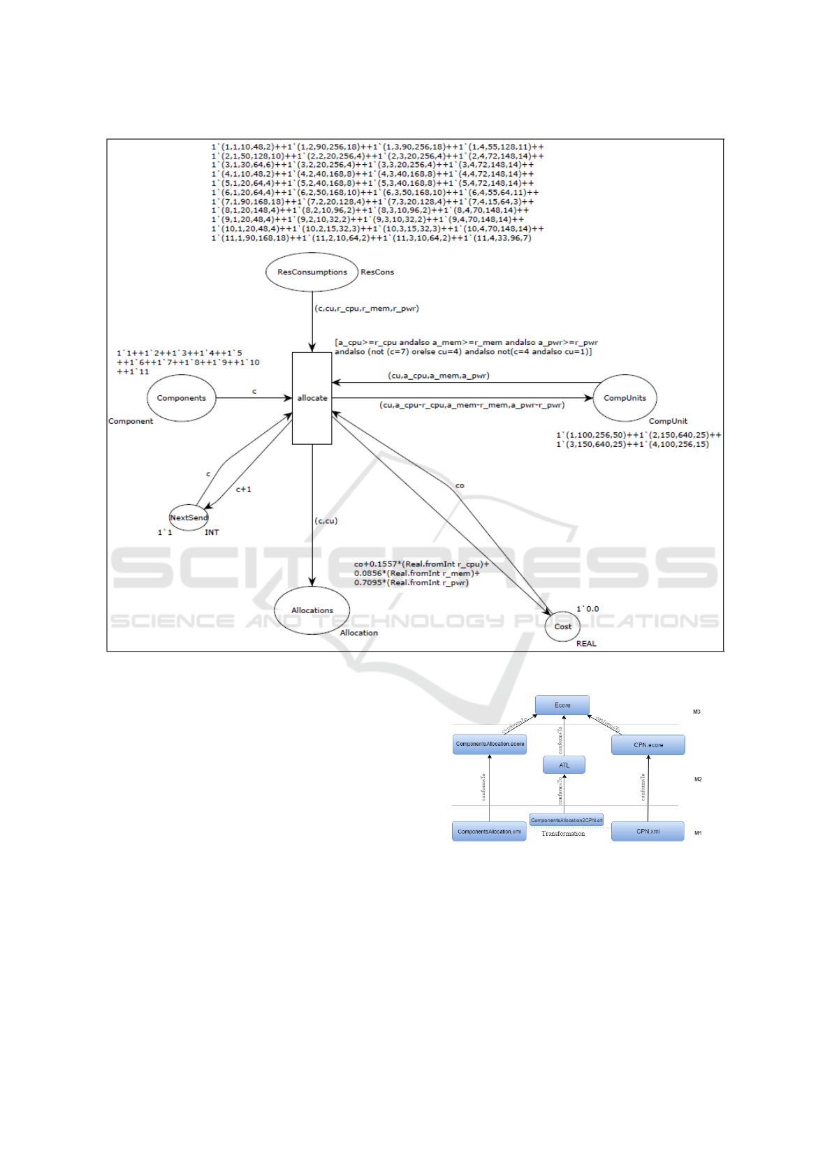
Figure 1: CPN model (extracted from (Al-Azzoni, 2015)).
case, is represented by Ecore, the metametamodel for
the entire transformation engine and is defined by it-
self. M2, the metamodel level is represented here by
ComponentAllocation.eore and CPN.ecore, which is
defined by M3. M1 is the model level and is de-
fined by M2. Figure 3 describes the component al-
location metamodel used in the scope of our transfor-
mation. The Component class contains Component-
Name, while the CompUnit class contains the Com-
pUnitName and the available resources for each one.
The ResConsumption class represents the amount of
resources consumed by component X while it is allo-
cated to CompUnit Y. The user can add the ResCon-
sumption to all components individually with any
CompUnit. If there is any constraint in the allocation,
the user can represent the constraints using Alloca-
tionConstraint or AntiAllocationConstraint classes;
the TradeOffVector class will indicate if there are any
trade-offs in the allocation problem.
Figure 2: ATL model transformation process.
Figure 4 describes the CPN metamodel used in the
scope of our transformation. The CompToken class
contains CompTokenName attribute taken from Com-
ponent class in the ComponentAllocation metamodel,
while the CompUnitToken class contains CompUnit
attribute that holds CompUnitName for each Com-
pUnit in the ComponentAllocation metamodel. The
ResConsToken class contains ResCons attribute for
Model-to-Model based Approach for Software Component Allocation in Embedded Systems
323
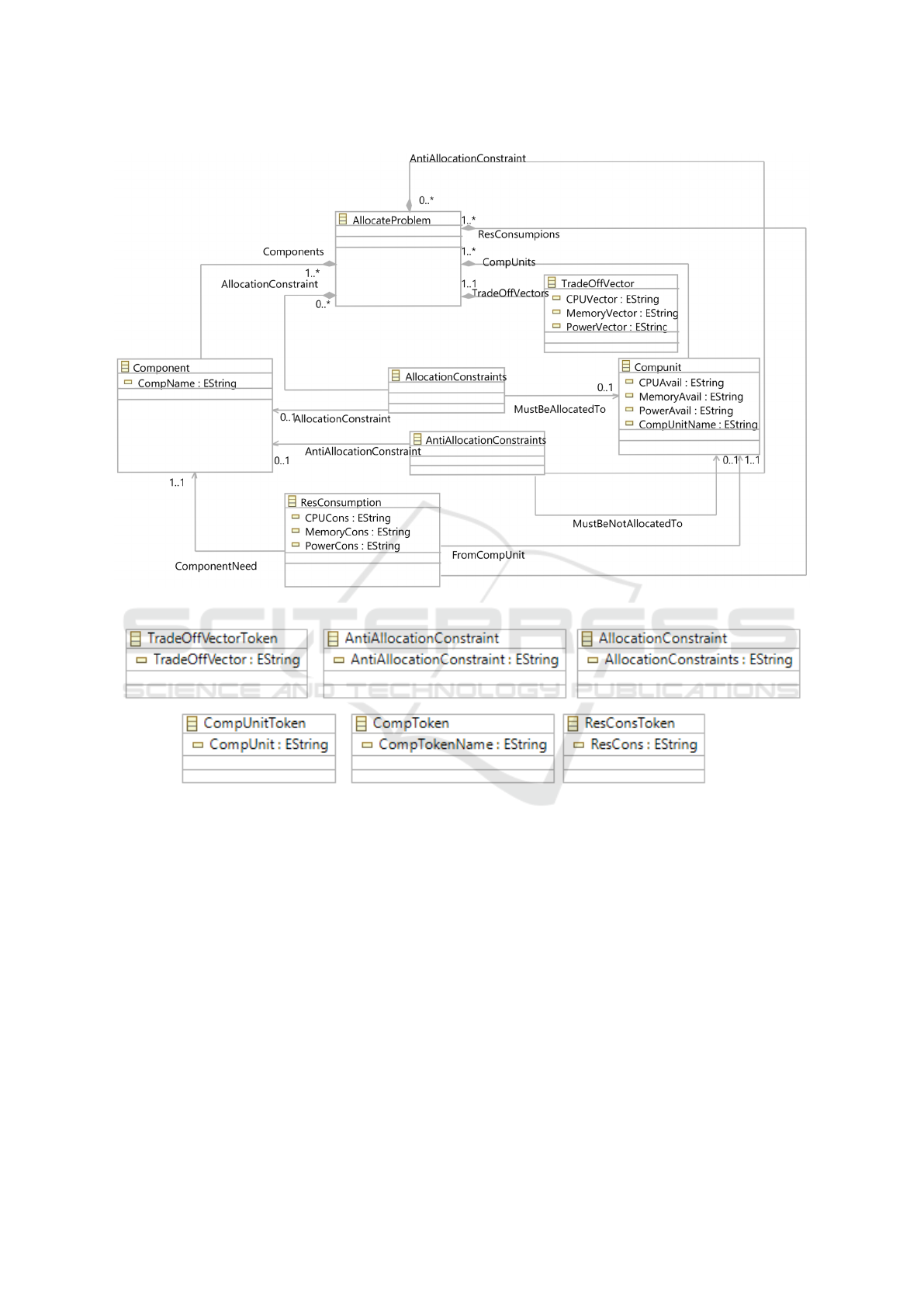
Figure 3: ComponentAllocation Ecore metamodel.
Figure 4: CPN metamodel.
the amount of resources consumed by a component
when its allocated to a computational unit. The com-
ponent allocation constraints are stored in Allocation-
Constraint and AntiAllocationConstraint classes. The
TradeoffVectorToken class contains a string defining
the tradeoff vectors of the allocation problem. The
ATL code for the ComponentAllocation2CPN.ATL
transformation consists of six rules.
-- First Rule
rule Component2Token {
from
A: ComponentAllocation!Component
to
Tokent1: CPN!CompToken
(CompTokenName <- A.CompName)
}
-- Second Rule
rule CompUnit2Token{
from
B: ComponentAllocation!Compunit
to
Token2: CPN!CompUnitToken
(CompUnit <- B.CompUnitName+’,’+B.CPUAvail+’,’
+B.MemoryAvail+’,’+B.PowerAvail)
}
-- Third Rule
rule TradeOffVector2Token{
from
C: ComponentAllocation!TradeOffVector
to
Token3: CPN!TradeOffVectorToken
(TradeOffVector <- ’co+’+C.CPUVector+’*
(Real.fromInt r_cpu)+’
+C.MemoryVector+’*(Real.fromInt r_mem)+’+
C.PowerVector+’*(Real.fromInt r_pwr)’)
MODELSWARD 2017 - 5th International Conference on Model-Driven Engineering and Software Development
324

}
-- Fourth Rule
rule ResCons2Token {
from
D: ComponentAllocation!ResConsumption
to
Token4: CPN!ResConsToken
(ResCons <- D.ComponentNeed.CompName+’,’+
D.FromCompUnit.CompUnitName+
’,’+D.CPUCons+’,’+D.MemoryCons+’,’+D.PowerCons)
}
-- Fifth Rule
rule Constraint {
from
E: ComponentAllocation!AllocationConstraints
to
Token5: CPN!AllocationConstraint
(AllocationConstraints <-
’(not(c=’+E.AllocationConstraint.CompName+
’)orelse cu=’+E.MustBeAllocatedTo.CompUnitName+
’)’)
}
-- Sixth Rule
rule AntiAllocationConstrait
{
from
F :
ComponentAllocation!AntiAllocationConstraints
to
AntiConstraint: CPN!AntiAllocationConstraint
(AntiAllocationConstraint <-
’c=’+F.AntiAllocationConstraint.CompName+
’andalso cu=’+F.MustBeNotAllocatedTo
.CompUnitName)
The first rule generates a token from a compo-
nent input element. The name of the generated token
is copied from CompName in the ComponentAlloca-
tion metamodel. The second rule generates the Com-
pUnit tokens. Each token should have CPU, memory,
and power capacity, which will be copied from the
class CompUnit in the ComponentAllocation meta-
model before collecting all the attributes together as
a single token. The ResConsumption rule will take
input from the component class through the Com-
ponentNeed association and an input from the Com-
pUnit class, the CompUnitName. It then will write
them together in an individual token with ResCon-
sumption attributes from the ComponentAllocation
metamodel. The TradeoffVector rule will write the
component problem tradeoffs in a single token, and
finally, the AllocationConstraint and AntiAllocation-
Constraint rules are responsible for transforming the
constraints defined in the ComponentAllocation to the
CPN constraint format as text.
One of the main challenges in this research was
how to make this transformation as powerful as pos-
sible while retaining the full benefits of the CPN Tools
in the SW-component allocation problem. All file for-
mats in the CPN Tools are XML based. For that, the
CPN Tools can not load any file unless it is XML
based. This issue was a challenge for our transforma-
tion tool because the ATL transformation generates
xmi files. The format of the XML files required by
CPN Tools is described in DTD with multiple restric-
tions provided in
3
. This file format is different from
the ATL’s generated file format. We overcame this
obstacle by developing a Java parser program that ob-
tains the output from ATL and writes it in the required
CPN Tools format. The supported tool reads xmi files
and obtains data from specific elements to add char-
acters and generate a string that is written into an out-
put XML file for use by the CPN Tools in creating a
model. In order to achieve this goal, we decided to
use an XML parser, which provided a way to access
and modify data in an XML document. Because xmi
is special form of XML, we can use the XML parser
in Java without any complications.
4 EVALUATION
In order to ensure the correctness of our transforma-
tion approach we evaluated it using static and dy-
namic analysis.
4.1 Static Analysis - anATLyzer
A transformation rule is written based on its source
and target metamodels, specifically to match between
elements from the source model and generate its cor-
responded elements in the target model. It describes
the structure of models manipulated by the transfor-
mation including the allowed types, relations, features
and its constraints. anATLyzer (Sanchez Cuadrado
et al., 2014) is a tool integrated with ATL as an
Eclipse plug-in which analyzes the transformation
to discover its potential problems and suggest many
ways to fix them. anATLyzer can identify problems
by combining static analysis and constraints solving.
Static analysis detects statements of the transforma-
tion that contain errors or may cause potential prob-
lems when executing the transformation. If the error
can not be detected in the transformation statement,
the constraints solver will find an input model that
cause the error occur to be better understood it by the
developer. We integrate anATLyzer with our ATL tool
3
http://cpntools.org/cpn2000/sgml vs xml
Model-to-Model based Approach for Software Component Allocation in Embedded Systems
325

and use it to analyze our transformation rules. Our
rules passed the rule conflict analysis. The only warn-
ing returned by the anATLyzer tool is that our com-
ponents in the target model are not connected. This is
fine since we declared each class to store separate to-
kens in order to reuse these tokens in the XMI parser.
4.2 Dynamic Analysis
The authors of (Selim et al., 2012) formulate the
model transformation testing into four phases. The
first phase is test case generation which involves gen-
erating test models conforming to the source meta-
model using some criteria to ensure that each test
model covers the source metamodel. The second
phase is assessing the generated test suite. The third
phase is building the oracle function which is used to
compare the actual transformation output with the ex-
pected output to evaluate the correctness of the trans-
formation. The fourth phase involves running the gen-
erated test models and comparing the output with the
oracle function results.
4.2.1 Test Model Generation - Black-Box Test
Model Generation Based on Metamodel
Coverage
The input scope for each test model is based on the
source metamodel. For that, each parameter in the
source metamodel is an input for the transformation.
The source metamodel used in this transformation is
an Ecore class diagram. For this purpose, we reused
adequacy criteria for UML class diagrams to ensure
the coverage for the test models. We used repre-
sentative values for the Association-End Multiplicity
(AEM) and the Class Attribute (CA) since the pos-
sible values of multiplicities and attributes are infi-
nite. We used default partitioning to extract values for
each attribute taking into consideration the structure
or type of the data. For a string attribute this would be
null, “something”, and for an [0..1] association end it
would be 0, 1. This policy suggests choosing bound-
ary values and in addition values outside the bound-
aries if the goal is to check the robustness of the trans-
formation.
4.2.2 Building the Oracle Function
In this phase, after generating the test models an ora-
cle function is used to compare the actual output with
the expected output to validate the transformation cor-
rectness. The oracle function used to test our ap-
proach was developed and presented in (Al-Dakheel,
L and Al-Azzoni, I, 2016). It is implemented as a Java
program that takes a component allocation problem
and generates an optimal allocation. It implements
full state enumeration that evaluates the cost for all
allocations and chooses an allocation that has the min-
imum cost.
4.2.3 Running the Transformation on the
Generated Test Models
Eight test models were used in our ATL tool. We first
created an instance for each model, then we loaded
the output into the XMI parser, which in turn con-
verted the output to an XML format accepted by the
CPN Tools. The goal was to enable the use of CPN
Tools by generating the required XML format.
4.2.4 Results
We achieved the results shown in Table 1 after loading
the XMI parser output to the CPN Tools as a net and
generating the state space to obtain an optimal allo-
cation. The table shows the optimal allocation cost
for using the oracle function and using our model-
based approach. This shows perfect accuracy of our
approach.
5 RELATED WORK
In the field of Model-to-Model Transformation
(MMT), the authors of (Andr
´
e et al., 2014) proposed
and implemented an approach to translate a UML
state machine diagram (SMD), into CPN in order to
use its formalization in analysis and verification. The
authors of (Hei et al., 2011) introduced an automated
transformation tool that transforms UML state charts
into Petri nets via extensible markup language (XML)
to analyze and verify the original UML model and
check its correctness in order to ensure safety anal-
ysis for systems using the transformation rules they
defined in an XML file.
The authors of (Choppy et al., 2011) proposed a
technique for the automated translation of UML state
diagrams into CPNs. The CPN model generated from
their approach was used in a CPN-AMI Petri netbased
case environment to check the correctness of the Petri
net model. Furthermore, the authors of (Guo et al.,
2014) discussed the absence of models in the field of
embedded systems and the limitations of semi-formal
models such as UML in addressing this problem. To
address these limitations, they proposed an automated
technique for the transformation of the UML state
machine model into the Simulink Stateflow model,
because Simulink is a formal semantic modeling lan-
guage that uses ATL as model-transformation archi-
tecture.
MODELSWARD 2017 - 5th International Conference on Model-Driven Engineering and Software Development
326

Table 1: Results of the oracle function VS. our approach. TM stands for Test Model.
TM1 TM2 TM3 TM4 TM5 TM6 TM7 TM8
Oracle Function
Results
176.61 159.77
No feasible
allocation
186.16 196.31 208.47 184.77 148.87
Our Approach
Results
176.61 159.77
No feasible
allocation
186.16 196.31 208.47 184.77 148.87
*
TM = Test Model
In order to identify the optimal SW-component al-
location, the authors of (
ˇ
Svogor et al., 2014a) applied
a genetic algorithm (GA) to identify optimal solutions
to the component allocation problem; they also ap-
plied an analytical hierarchical process to address the
problem of different measurement units in the calcu-
lation of trade-off factors.
However, although GA usually finds a good so-
lution, there is no guarantee that these solutions will
be optimal. Another method for solving the compo-
nent allocation problem was presented in (Wang et al.,
2004). The method uses branch-and-bound and for-
ward checking mechanisms. The method was imple-
mented in the Automatic Integration of Reusable Em-
bedded Software (AIRS) toolkit
4
.
Obviously, there is still a clear gap on the mod-
eling language that addressed the problem of SW-
component allocation on embedded systems. The au-
thor of (Al-Azzoni, 2015) was the first to present a
model-based approach for modeling and solving the
SW-component allocation problem using CPN. He
used CPN as a modeling language and described the
use of CPN Tools in analyzing the CPN model and
solving the component problem. Using CPN to ad-
dress the SW-component allocation problem will not
only optimize the cost function, but will also optimize
allocation for other types of nonfunctional analysis,
including security and dependability analysis.
6 CONCLUSION AND FUTURE
WORK
In this paper, we have described an automated model-
to-model transformation approach for software com-
ponent allocation in embedded systems, which was
developed to benefit from the mathematical power of
CPN. We have demonstrated full accuracy in our re-
sults regarding finding the optimal cost for the prob-
lem of SW-component allocation in embedded sys-
tems using only a simple Ecore diagram followed by
its transformation into the corresponding CPN model.
We concluded that the MMT tools have deservedly
4
http://kabru.eecs.umich.edu/bin/view/Main/AIRES
received a great deal of attention from researchers
because they lead to satisfactory results. However,
we investigated the existing work related to identify-
ing the optimal SW-component allocation and deter-
mined there is a clear gab in the modeling languages
and model transformations as they pertain to the SW-
component allocation problem in heterogeneous em-
bedded systems. This study is the first to close the gas
in this field by identifying a new model that not only
addresses the problem of SW-component allocation
but transforms it into a formal and analyzable CPN
model automatically. We accomplished our transfor-
mation in two primary steps. The first was transform-
ing the input model into CPN tokens in an XMI file
followed by rewriting the tokens as a CPN model in
an XML file using a supported XMI parser.
As a future work, several research activities open
directly from the contributions of this paper. First, we
plan on combining our ATL transformation technique
and the XMI parser into a stand-alone application. To
do so, we need to first run the ATL transformation into
a programming environment and then combine it with
the XMI parser. Second, although we obtained full
accuracy in our test results, more test models need to
be conducted with a variety of problem sizes in order
to further validate our transformation approach.
REFERENCES
Al-Azzoni, I. (2015). Software component allocation
on heterogeneous embedded systems using coloured
petri nets. In Proceeding of SOFTENG,The First In-
ternational Conference on Advances and Trends in
Software Engineering, pages 23–28.
Al-Dakheel, L and Al-Azzoni, I (2016). Model-to-Model
Based Approach for Software Components Allocation
in Embedded Systems. Masters Thesis, King Saud
University, Software Engineering Department.
Andr
´
e, E., Benmoussa, M. M., and Choppy, C. (2014).
Translating UML state machines to coloured petri
nets using Acceleo: A report. arXiv preprint
arXiv:1405.1112.
Biermann, E., Ehrig, K., Ermel, C., K
¨
ohler, C., and
Taentzer, G. (2008). The EMF model transformation
framework. Applications of Graph Transformations
with Industrial Relevance, pages 566–567.
Model-to-Model based Approach for Software Component Allocation in Embedded Systems
327

Carlson, J., Feljan, J., M
¨
aki-Turja, J., and Sj
¨
odin, M.
(2010). Deployment modelling and synthesis in a
component model for distributed embedded systems.
In Proceeding of Software Engineering and Advanced
Applications (SEAA), 2010, pages 74–82. IEEE.
Choppy, C., Klai, K., and Zidani, H. (2011). Formal veri-
fication of UML state diagrams: a Petri net based ap-
proach. ACM SIGSOFT Software Engineering Notes,
36(1):1–8.
Force, U. R. T. (2010). OMG Unified Modeling Language:
Superstructure. Technical report.
Guo, P., Li, Y., Li, P., Liu, S., and Sun, D. (2014). A UML
model to simulink model transformation method in
the design of embedded software. In Proceedings of
the conference on Computational Intelligence and Se-
curity (CIS), pages 583–587.
Hei, X., Chang, L., Ma, W., Gao, J., and Xie, G. (2011). Au-
tomatic transformation from UML statechart to Petri
nets for safety analysis and verification. In Proceed-
ings of the Quality, Reliability, Risk, Maintenance,
and Safety Engineering, pages 948–951.
Jensen, K. (2013). Coloured Petri nets: Basic Con-
cepts, Analysis Methods and Practical Use, volume 1.
Springer Science & Business Media.
Jensen, K. and Kristensen, L. M. (2009). Colored petri nets:
Modelling and Validation of Concurrent Systems, vol-
ume 978.
Petri, C. A. and Reisig, W. (2008). Petri nets. Scholarpedia,
3(4):64–77.
Sanchez Cuadrado, J., Guerra, E., and De Lara, J. (2014).
Uncovering errors in atl model transformations using
static analysis and constraint solving. In In proceed-
ings of the IEEE International Symposium on Soft-
ware Reliability Engineering (ISSRE), pages 34–44.
IEEE.
Selim, G. M., Cordy, J. R., and Dingel, J. (2012). Model
transformation testing: the state of the art. In Proceed-
ings of the First Workshop on the Analysis of Model
Transformations, pages 21–26. ACM.
ˇ
Svogor, I., Crnkovic, I., and Vrcek, N. (2014a). An ex-
tended model for multi-criteria software component
allocation on a heterogeneous embedded platform.
Journal of Computing and Information Technology,
21(4):211–222.
ˇ
Svogor, I., Crnkovic, I., and Vrcek, N. (2014b). An ex-
tended model for multi-criteria software component
allocation on a heterogeneous embedded platform.
Journal of Computing and Information Technology,
21(4):211–222.
Wang, S., Merrick, J. R., and Shin, K. G. (2004). Com-
ponent allocation with multiple resource constraints
for large embedded real-time software design. In
Real-Time and Embedded Technology and Applica-
tions Symposium, 2004. Proceedings. RTAS 2004.
10th IEEE, pages 219–226. IEEE.
Wimmer, M., Kappel, G., Kusel, A., Retschitzegger, W.,
Sch
¨
onb
¨
ock, J., Schwinger, W., Kolovos, D., Paige, R.,
Lauder, M., Sch
¨
urr, A., et al. (2011). A comparison
of rule inheritance in model-to-model transformation
languages, pages 31–46. Springer.
MODELSWARD 2017 - 5th International Conference on Model-Driven Engineering and Software Development
328
