
Fast Eye Tracking and Feature Measurement using a Multi-stage
Particle Filter
Radu Danescu
1
, Adrian Sergiu Darabant
2
and Diana Borza
1
1
Department of Computer Science, Technical University of Cluj-Napoca, 28 Memorandumului Street,
Cluj-Napoca, Romania
2
Department of Computer Science, Babes-Bolyai University, 58-60 Teodor Mihali street, Cluj-Napoca, Romania
radu.danescu@cs.utcluj.ro, dadi@cs.ubbcluj.ro, diana.borza@cs.utcluj.ro
Keywords: Eye Tracking, Particle Filters, Real Time, Blink Detection, Deformable Model.
Abstract: Eye trackers – systems that measure the activity of the eyes – are nowadays used in creative ways into a
variety of domains: medicine, psychology, automotive industry, marketing etc. This paper presents a real time
method for tracking and measuring eye features (iris position, eye contour, blinks) in video frames based on
particle filters. We propose a coarse-to-fine approach to solve the eye tracking problem: a first particle filter
is used to roughly estimate the position of the iris centers. Next, this estimate is analysed to decide the state
of the eyes: opened or half-opened/closed. If the eyes are opened, two independent particles filters are used
to determine the contour of each eye. Our algorithm takes less than 11 milliseconds on a regular PC.
1 INTRODUCTION
Eye trackers measure the eye positions and
movements and are currently being used in a wide
variety of disciplines, including medicine,
psychology, marketing research and human computer
interaction (HCI).
Over the past decades active research studies were
conducted in order to detect and track the eyes, but,
despite their apparent simplicity, as humans can
detect them with no effort, this proved to be a difficult
task. It is quite challenging trying to group the
proposed eye tracking methodologies into a single
and unitary taxonomy. In (Hansen, 2010) the authors
present a detailed survey of the eye models used in
recently published eye tracking systems. Eye tracking
systems are classified as: shape based, appearance
based and hybrid methods.
Shape based methods use a prior geometrical
model of the eye and a similarity measure. Such
methods often impose a circularity constraint (for the
iris or pupil) (Daugman, 2002) and therefore they are
only suitable for near-frontal images. Other methods
use more complicated models, by also modelling the
eyelids ((Yuille, 1989), (Borza, 2016)). Appearance
based methods (Sirohey, 2001) use information about
the colour distribution and/or filter responses near the
eye region to detect and track the eyes. Their main
drawback is that they require large amount of training
data under different conditions (illumination, pose,
occlusions etc.). Finally, hybrid methods combine the
previous two approaches in order to overcome their
drawbacks (Cristinacce, 2008).
Based on the light source used to track the eyes,
the proposed models can be split into active light
models (Morimoto, 2000) – that use infrared (IR)
illuminators and rely on a physical property of the
pupil that modifies its appearance in the captured
image depending on the position of the IR light source
– and passive light models – that use the ambient
light, in the visible spectrum. A lot of research works
have been focusing on active light methods, but their
main drawback is that outdoor use of such systems
can be problematic because of environmental
(extreme light, etc.) conditions.
More recently, particle filters (Isard, 1998)
emerged as an efficient method for eye tracking
systems, due to their improved performance and
adaptability. The approach proposed in (Campos,
2013) relies on a chain of Haar classifiers that enable
a fast recognition of the eye regions and on particle
filtering for tracking the eyes. The system uses the
physical properties and the dynamics of pupils to
detect the eye regions. However, this approach only
roughly tracks the eye positions, and no information
about the eye shape, blinking or iris position is
computed.
258
Danescu R., Sergiu Darabant A. and Borza D.
Fast Eye Tracking and Feature Measurement using a Multi-stage Particle Filter.
DOI: 10.5220/0006130202580265
In Proceedings of the 12th International Joint Conference on Computer Vision, Imaging and Computer Graphics Theory and Applications (VISIGRAPP 2017), pages 258-265
ISBN: 978-989-758-226-4
Copyright
c
2017 by SCITEPRESS – Science and Technology Publications, Lda. All rights reserved
Wu (Wu, 2007) proposed a system for
simultaneous eye tracking and blink detection. They
used two interactive particle filters for modelling the
dynamics of open-eye and closed-eye separately: one
of them is used for tracking the eye localization by
exploiting auto-regression models for describing the
state transition and a classification-based model in
tensor subspace for measuring the observation. One
particle filter tracks the closed eyes and the other one
tracks the open eyes. A second-order auto-regression
model describes the eye’s movement, while a first-
order auto-regression model describes the scale
transition. The system integrates tensor subspace
analysis for feature extraction, while logistic
regression is applied for evaluating the posterior
probabilities. A more elaborated version of this work
was published in (Wu, 2010): the system was
integrated into a smart environment that also includes
facial features detection and localization.
In (Li, 2010) the eyes are tracked using a
deformable eye template which can describe both
open and closed eye states that is integrated into a
particle filtering framework. The measurement model
is based on the contour tracking method that was first
proposed in (Isard, 1998), but which was adapted for
eye tracking. The main drawback of this work is that
the eye corners and the eyelid apexes must be
manually marked in the initial frames.
In this paper, we propose a fast method for
tracking and measuring the eyes features using a two
stage particle filter. Our method robustly detects the
iris centers as well as the eye contours. In the first
stage, the iris center positions and the eyes orientation
are roughly estimated, and in the second stage the eye
contours are determined.
The remainder of this paper is organized as
follows: in Section 2 we show the outline of the
proposed solution and in Section 3 we provide its
detailed description. In Section 4 we present and
discuss the experimental results. Section 5 shows the
conclusions and the proposed future improvements of
this work.
2 SOLUTION OUTLINE
The proposed solution uses a coarse-to-fine approach
to detect and track multiple features of the eyes: iris
centers, eye contour and eye-blinks. The outline of
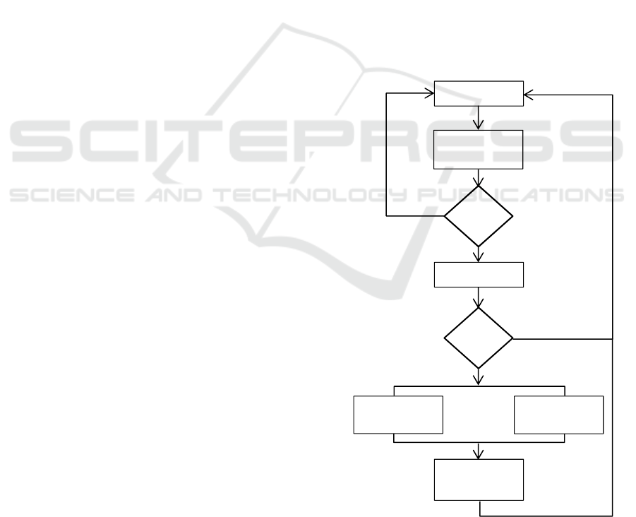
the solution is depicted in Figure 1. The solution uses
three particle filters in parallel to track the eyes: the
first particle filter is used to coarsely determine the
iris positions. Two other particle filters are used to
determine and track the contour of each eye based on
the estimate obtained from the first one.
The first stage uses a particle filter to roughly
estimate the position of the iris centers and the eyes’
orientation (angle between the line connecting the
two eyes and the horizontal axis). On the first video
frame, the particle filter is initialized: the face is
detected in the input image and the search space is
uniformly covered by randomly generating particles
to the entire input space.
The particle filtering algorithm is iteratively run
on each frame in order to obtain the rough position of
the eyes.
Periodically, the obtained estimate undergoes a
validity check: the face is detected in the current
frame and we check if the estimated eye positions are
located in the approximate area of the eyes (the upper
half region of the face). If the estimate is no longer
valid, then the tracking is re-initialized from the
current frame.
If the estimate is valid, it is analysed in order to
determine if it corresponds to an open or to a closed
eye.
Figure 1: Multistage particle filter.
Initialization
Eye Position
Particle Filter
Valid
Blink detection
Blink
Left Eye shape
Particle Filte
r
Right Eye shape
Particle Filte
r
Eye shape
estimation
Yes
Estimate
N
o
Yes
No
Left Eye
estimate
Right Eye
estimate
Fast Eye Tracking and Feature Measurement using a Multi-stage Particle Filter
259

3 SOLUTION DESCRIPTION
3.1 Particle Filters
Particle filters (bootstrap filters or condensation
algorithm) are state estimation techniques usually
used for non-Gaussian and multimodal probability
distribution functions (pdf). Particle filters are applied
in object tracking problems, where the state of the
systems changes over time and information about the
new state are obtained via noisy measurements at
each iteration.
The main idea of a particle filter is to represent the
posterior probability function by a set of N weighted
particles, P(X) = {X
i
, π
i
, i = 1,
}, where each particle
represents an hypothesis of the object that is being
tracked. All the weights are normalized so that they
sum up to one.
The filter is an iterative process and it involves the
following three steps: resample, predict and measure
/ update. The particle filter flow is illustrated in
Algorithm 1:
BEGIN PARTICLE FILTER ITERATION (P –
particle set)
RESAMPLE
- Compute cumulative sum of
particle weights CDF
- P` ← []
- FOR I ← 0: N
o r ← rand(0, 1)
o k ← 0
o WHILE r > CDF[k]
k ← k + 1
o END WHILE
o Insert P[K] into P`
- END FOR
- Return new weightless particle
set P`
PREDICT likelihood of each possible
particle (deterministic drift and
stochastic diffusion)
MEASURE against the image features
and assign weights to the particles
END.
For the resampling step, we perform N random
draws with replacement based on the particle weights.
Therefore, a particle with a higher weight is likely to
be selected multiple times, while a lower weight
particle might not be selected at all. After this step, a
new set of weightless particles is obtained, with an
uneven concentration, which approximates the same
pdf. In addition, at each iteration, R% of the N
particles will be randomly selected by sampling from
the uniform probability distribution function in order
to ensure that the current estimate does not fall into a
local minimum.
Next, in the prediction step, the new particle set is
modified according to the system’s transition. A
stochastic diffusion is also applied in order to
consider the random events that might influence the
system state. In the measurement / update state, the
posterior probability density function is obtained by
simply weighting the distribution of weightless
particles (the prior state probability distribution)
according to the likelihood of observation.
The estimation
of the tracked object at each time
step t can be obtained by simply combining the
particles (or a subset of particles) according to their
weights:
S
= π
i
s(X
i
)
M
i = 1
(1)
, where s(X
i
) is the state vector that describes the
particle X
i
and
is the particle weight.
3.2 Eye Position Estimation
In the first stage of the algorithm the eye position is
roughly estimated: only the iris centers and the eyes’
orientation are determined.
The eye position is fully described by the
following state vector (2):
(x
l
, y
l
) left iris center
ipd pupillary distance
θ eye orientation
(2)
, where (x
l
, y
l
) is the center of the left eye position, ipd
is the distance between the left and the right pupil
centers and is the rotation of the eyes in the frontal
plane.
By using this feature vector instead of two
simultaneous independent iris trackers, we also
include the relationship between the two eyes in the
feature vector and we reduce the computational costs.
The particle used model the eye pair is depicted in
Figure 2.
3.2.1 Symmetry Transformation
To evaluate the circular symmetry of the irises we
used Fast Radial Symmetry Transform (FRST) (Loy,
2003), a simple and fast image transformation which
uses image gradients to detect regions of high radial
symmetry.
VISAPP 2017 - International Conference on Computer Vision Theory and Applications
260
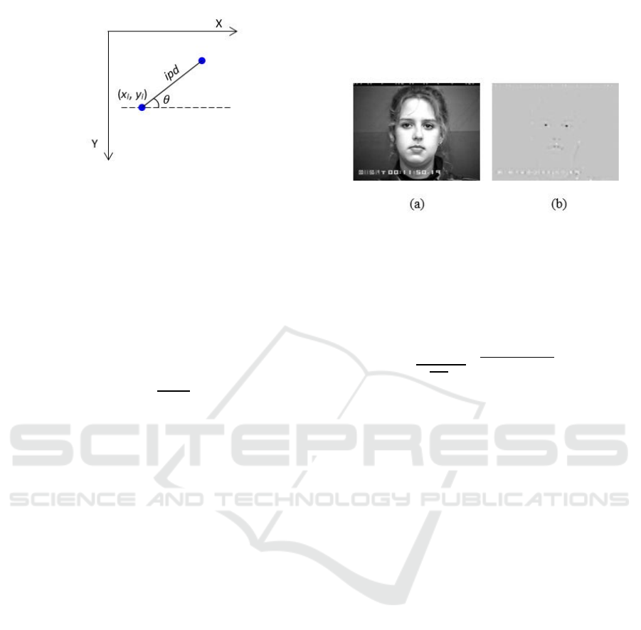
Figure 2: Eye position particle. The iris centers are depicted
in blue circles: (x
l
, y
l
) are the coordinates of the left iris
center, ipd is the inter-pupillary distance and is the
rotation angle between eyes.
For each pixel p under consideration, two
neighbouring pixels at a distance r away from p are
determined: p
+
(the positively affected pixel) or the
pixel the gradient is pointing to, and p
-
(the negatively
affected pixel) or the pixel the gradient g(p) is
pointing away from.
p
±
= p ± round
g(p)
|
g(p)
|
r
(3)
Based on these neighbouring pixels the magnitude
projection image M
r
and the orientation projection
image O
r
are formed iteratively (4).
M
r
p
±
= M
r
p
±
± g
p
O
r
p
±
= O
r
p
±
± 1
(4)
The radial symmetry transform at radius r is
defined by the convolution:
S
r
= F
r
* A
r
(5)
, where
F
r
= ||O
r
p
||
(α)
M
r
(p)
(6)
A
r
is an isotropic Gaussian smoothing kernel used
to spread the symmetry contribution, and O
r
and
M
r
are the normalized orientation and magnitude
projection images.
The full transform S is computed over a set of
radii:
S = S
r
r
(7
)
The radial symmetry was tuned so that only dark
symmetrical regions are found, as the iris and pupil
area are darker that the surrounding neighbourhood:
only the negatively affected pixels (p-) were used to
update the images O
r
and M
r.
The search radii for the
iris were determined based on the canonical facial
proportions. Figure 3 shows the symmetry
transformation for a grayscale input image.
Figure 3: Symmetry transform image. (a) Grayscale image;
(b) Corresponding symmetry transformation. Darker
regions correspond to areas that have a high circular
symmetry.
The measurement probability of the i
th
particle X
i
is defined as:
π
i
=
1
(
√
2π σ)
2
e
-
S
xl, yl
+S(xr, yr)
2σ
2
(8)
where S(x
l
, y
l
) is the value of the symmetry transform
image in the hypothetical left iris center and S(x
r
, y
r
)
is the value of the symmetry transform image in the
hypothetical right iris center. This weight indicates
how much the current estimate matches the ground
truth location of the eyes.
The particle filter iterations, resample, predict and
measure are iteratively applied on each frame.
The eye position at each frame is estimated by
splitting the particle set into several disjoint-set data
sets (Cormen, 2001) based on the iris positions and
orientation. The set that contains the particles with the
highest average score is selected, and the estimate is
computed by taking the weighted average of all the
particles that belong to this set (1). We preferred this
approach, rather than a simple weighted average of
the best particles, because the orientations of the eye
hypotheses can have different signs and by adding
positive and negative numbers the orientation
contributions can be lost.
Next, the current estimate is analysed to
determine whether the eye is closed or not. To make
this decision, we used the following constraint: we
presume that the eyes are opened in the first frames
of the video sequence and we “learn” a threshold for
the open eyes by averaging the weights of the first L
= 7 frame estimates. As the first particle filter,
roughly estimates the iris centers, we argue that the
symmetry of the iris is not observable when the eye is
(semi-)closed.
After learning this threshold (from the (L + 1)
th
frame) we compare the estimate score with this
Fast Eye Tracking and Feature Measurement using a Multi-stage Particle Filter
261
threshold; if its score is lower than this threshold we
assume that the eye is closed. Otherwise, the eye is
considered to be opened.
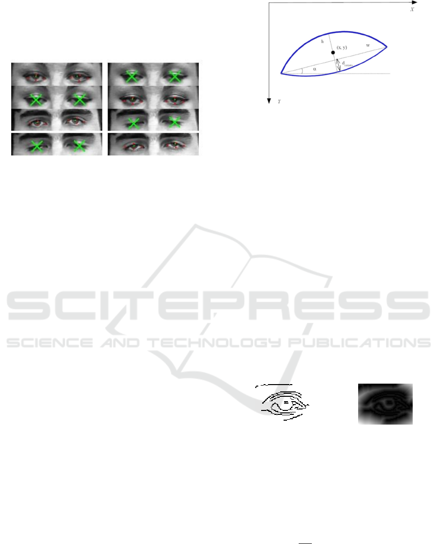
Figure 4 shows the tracking result in some blink
and half-closed eyes cases.
Figure 4: Tracking results in case of blinking and eye
closure. The iris centers are marked with green crosses and
the eye landmarks (eye corners and eyelid apexes) are
marked in red circles. In the case of blinking, two green Xs
are drawn over the eye area.
The main drawback of this simple procedure is
that it is sensitive to illumination changes and it is
based on a constraint (the image sequence must begin
with the eyes open) that cannot always be fulfilled.
3.3 Eye Shape Estimation
Following the approximation of the iris position, if
the eye is open, we proceed to the estimation of the
eye contour.
The eye contour particle (Figure 5) is defined by
the following state vector (8):
(x , y) eye cente
r
weye width
h eye height
α eye orientation
d
corners
corners
y
distance
(9)
(x, y) are the coordinate of the center of the eye, w
and h are the eye width and height respectively, is
the eye orientation and
determines the
vertical position of the eye corners (as a percent of the
eye height h) starting from the lower eyelid apex.
Using this deformable template model we can model
the eyes in both open and closed states (the eye is
closed or half closed if the height of the eye is close
to 0).
Figure 5: Eye shape particle visual representation. The eye
contour is represented by the blue parabola. The point (x, y)
is the centroid of the eye shape, α is the orientation of the
eye, d
corners
is the vertical position of the eye corners, and w
and h are the eye width and height, respectively.
By using a two stage approach (first we determine
the approximate eye position and then we use
independent trackers for the eye contour) we reduce
the computational cost of the algorithm. The main
bottleneck of the particle filter is the
measurement/update phase; by using a simplified eye
model to find the position of the eyes and two
independent particle filters to determine the shape of
the eyes the measurement function can also be
significantly simplified.
3.2.1 Distance Transformation
Distance transform or distance map is a
representation of a binary image, in which each pixel
indicates the distance to the nearest object/obstacle
point. Figure 6 shows the Canny edge map for an eye
image and the corresponding distance transformation.
(a) (b)
Figure 6: (a) Canny edge map. (b) Distance transformation.
This image representation can be used to
determine the degree to which an objects fits an input
image by simply superimposing the contour of the
object over the distance transformation and adding
the pixels values that lies under the contour:
D
edge
=
1
|
Ω
|
DT(x, y)
x,
y
∈Ω
(10)
, where |Ω| is the length of the contour of the eye Ω
and DT(x, y) is the value of the pixel in the distance
transform map at coordinates (x, y).
VISAPP 2017 - International Conference on Computer Vision Theory and Applications
262
To compute the eye contour estimate, we select
the fittest ε = 0.3 × N particles (P) and combine them
into a weighted average according to their weights:
S
=
∑
π
i
s(X
i
)
X
i
∈P
∑
π
iX
i
∈ P
(11)
, where s(X
i
) is the state vector of the i
th
particle
and π
i
is the weight of that particle.
4 EXPERIMENTAL RESULTS
The proposed solution was tested both on video
frames captured in our lab and on image sequences
from the publically available Extended Cohn-Kanade
database ((Kanade, 2000), (Lucey, 2010)).
The Extended Cohn-Kanade database (ck+)
contains 593 image sequences from 123 individuals
of different races and ages (18 – 50 years) which
perform various facial expressions. The subjects were
asked to perform a set of 23 facial displays; each
image capturing session begins and ends with a
neutral display. The images have 640x480 or
640x490 pixels resolution.
The eye tracking method is implemented in C++
and all the experiments were performed on a PC with
a 4
th
generation Intel Core i7 processor (2.4 GHz).
In our experiments, the particle filter used to
determine the iris center and the orientation of the eye
uses N = 200 particles, and each one of the two
particle filters used to find the shape of the eye uses
N = 200 particles.
The average execution time of the proposed
solution is, in average, less than 11 milliseconds on
640x480 face images on a 4
th
Generation Intel i7
CPU.
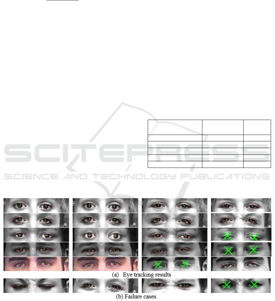
Several tracking results are shown in Figure 7.
We used two metrics to evaluate the performance
of the proposed solution: the Euclidian distance D
between the estimated eye landmarks and their real
location and normalized Euclidian distance
. By
normalizing the errors we obtain a numerical value of
the error that is independent of the image resolution.
Table 1 shows the performance results on the
Extended Cohn-Kanade database. In the case of eye
corners and eyelid apexes the Euclidian distance is
normalized with the average width of the eye, and in
the case of iris centers the metric is normalized with
the inter-pupillary distance.
Table 1: Average errors on the Extended Cohn-Kanade
(ck+) database.
Feature
D
(pixels)
(%)
Temporal eye corner 4.88 0.11
Nasal eye corner 6.42 0.14
Upper eyelid apex 3.15 0.07
Lower eyelid apex 2.69 0.06
Iris center 5.3 0.05
Figure 8 and 9 show the ROC curves for the eye
corners and the eyelids apexes, respectively.
Figure 7: Eye tracking results and failure cases. The eye landmarks (eye corners and eyelid apexes) are depicted in rec circles
and the iris center is marked in with a green cross. When the eye is detected as closed, the eyes are marked with a green X
sign.
Fast Eye Tracking and Feature Measurement using a Multi-stage Particle Filter
263
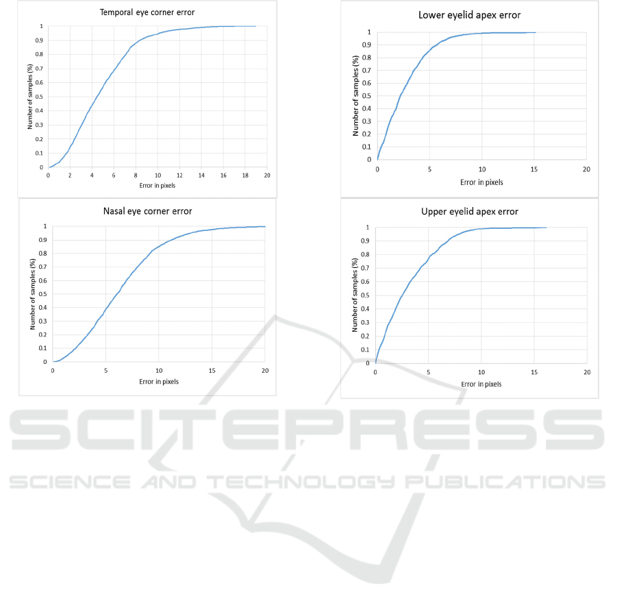
Figure 8: Cumulative error distribution for the eye corners.
In the rest of this section, we will compare the
proposed methods with other works published in the
specialized literature.
In (Campos, 2013) the eye tracking is performed
using two particle filters for each eye, where one
particle filter estimates the x position and other one
the y position of the eye. However, the algorithm only
outputs the location of the eyes as a circle with a (x,
y) position; it doesn`t give any information about the
iris position, blinks or eye shape. The runtime of the
algorithm is not specified in the manuscript, only that
“the eyes are detected in real-time video images”
(Campos, 2013).
(Wu, 2007) proposed a method to simultaneously
track the eyes and detect blinking. Two particle filters
are used: one particle filter tracks the closed eyes and
the other one the open eyes. The particle set with the
highest confidence is used to detect the eyes position
and their state (open or closed). This work estimates
only the bounding rectangle of each eye.
In (Li, 2010) the eyes are tracked using a
deformable model of the eyes and a particle filter.
This method outputs information about the eye shape
and can track the eyes even when they are closed by
including three eye states (open, half-closed and
closed) in the eye model.
Figure 9: Cumulative error distribution for the eyelid
apexes.
However, this method tracks only the contour of
the eye, without the iris center. Our method also
tracks the irises. The root mean square error of the
method proposed in (Li, 2010) was computed on an
image sequence with 950 frames where the width of
a single eye region is approximately 32 pixels. The
reported error is on average 4 pixels; the error is
approximately 12.5% of the eye width.
We tested our method on the Extended Cohn-
Kanade database, where the mean eye width is about
50 pixels and obtained an average error of 4.29 pixels
(9.73% of the eye width), which is at least comparable
if not better with the one obtained by (Li, 2010). In
addition, in (Li, 2010) “for initial frames, the
locations of the eye corners and the apexes of eyelids
are manually marked”. Our method does not involve
any manual initialization.
5 CONCLUSIONS
In this paper, we present a fast multi-stage particle
filter framework to detect and track multiple eye
features: iris centers, blinks, eye contours. The
method uses a coarse-to-fine approach to find all
VISAPP 2017 - International Conference on Computer Vision Theory and Applications
264

these features: first, a simple particle filter is used to
approximate the iris center positions and the eye
orientation. Next, a simple threshold of the score of
this estimate is used to decide whether the eye is
closed or not. If the eyes are open, two particle filters
are updated and used to estimate the full contour of
the eye. The algorithm runs in less than 11
millisecond on a regular PC.
The method is robust to short time eye occlusions
and it can detect and track the human eyes without
any type of manual initialization, camera calibration
or user preregistration.
As a future work, we plan to improve our eye
blink detection method. The current method, the
simple thresholding of the iris particle estimation, is
not very robust and can be strongly influenced by
illumination changes. We intend to train a classifier,
for example, a support vector machine (SVM), to
decide whether the eye is closed or not.
Another improvement will involve using optical
flow in order to guide the particle filters, by updating
the state changes of the eyes.
The performed experiments demonstrate the
effectiveness of the proposed solution under different
facial expressions and illumination conditions.
ACKNOWLEDGEMENTS
This work was supported by the MULTIFACE grant
(Multifocal System for Real Time Tracking of
Dynamic Facial and Body Features) of the Romanian
National Authority for Scientific Research, CNDI–
UEFISCDI, Project code: PN-II-RU-TE-2014-4-
1746.
REFERENCES
Borza, D., Darabant, A. S., and Danescu, R. (2016).
Realtime detection and measurement of eye features
from color images. Sensors, 16(7):1105.
Campos, R., Santos, C., and Sequeira, J. (2013). Eye
tracking system using particle filters. In IEEE 3rd
Portuguese Meeting in Bioengineering, 1–4.
Cormen, T. H., Stein, C., Rivest, R. L., and Leiserson, C. E.
(2001). Introduction to Algorithms. McGraw-Hill
Higher Education, 2nd edition.
Cristinacce, D. and Cootes, T. (2008). Automatic feature
localisation with constrained local models. Pattern
Recogn., 41(10):3054–3067.
Daugman, J. (2002). How iris recognition works. IEEE
Transactions on Circuits and Systems for Video
Technology, 14:21-30.
Hansen D.W. and Q. Ji. (2010). In the Eye of the Beholder:
A Survey of Models for Eyes and Gaze. IEEE
Transactions on Pattern Analysis and Machine
Intelligence, 32(3): 478-500.
Isard, M. and Blake, A. (1998). Condensation – conditional
density propagation for visual tracking. International
Journal of Computer Vision, 29:5-28.
Kanade, T., Cohn, J. F., and Tian, Y. (2000).
Comprehensive database for facial expression analysis.
In 4
th
IEEE International Conference on Automatic
Face and Gesture Recognition, Grenoble, France, 46-
53.
Li, Y., Wang, S., and Ding, X. (2010). Eye/eyes tracking
based on a unified deformable template and particle
filtering. Pattern Recognition Letters, 31(11):1377 -
1387.
Loy, G. and A. Zelinsky. (2003). Fast Radial Symmetry for
Detecting Points of Interest. IEEE Transactions on
Pattern Analysis and Machine Intelligence, 25(8): 959-
973.
Lucey, P., Cohn, J. F., Kanade, T., Saragih, J., Ambadar, Z.,
& Matthews, I. (2010). The Extended Cohn-Kanade
Dataset (CK+): A complete expression dataset for
action unit and emotion-specified expression. In 3
rd
Workshop on CVPR for Human Communicative
Behavior Analysis, San Francisco, USA, 94-101.
Moore, R. and Lopes, J. (1999). Paper templates. In
TEMPLATE’ 06, 1st International Conference on
Template Production. SCITEPRESS.
Morimoto, C. (2000). Pupil detection and tracking using
multiple light sources. Image and Vision Computing,
18(4):331–335.
Sirohey, S. A. and Rosenfeld, A. (2001). Eye detection in a
face image using linear and nonlinear filters. Pattern
Recognition, 34(7):1367–1391.
Smith, J. (1998). The Book. The publishing company,
London, 2nd edition.
Wu, J. and Trivedi, M. M. (2008). Simultaneous eye
tracking and blink detection with interactive particle
filters. EURASIP J. Adv. Sig. Proc., 2008.
Wu, J. and Trivedi, M. M. (2010). An eye localization,
tracking and blink pattern recognition system:
Algorithm and evaluation. ACM Trans. Multimedia
Comput. Commun. Appl., 6(2):8:1–8:23.
Yuille, A. L., Hallinan, P.W., and Cohen, D. S. (1992).
Feature extraction from faces using deformable
templates. Int. J. Comput. Vision, 8(2):99–111.
Fast Eye Tracking and Feature Measurement using a Multi-stage Particle Filter
265
